Article Outline
2. Overview on the light transmission systems
3. Research aims and motivation
Declaration of competing interest
Figures and tables
Volume 7 Issue 2 pp. 186-200 • doi: 10.15627/jd.2020.17
A Novel Approach to Multi-Apertures and Multi-Aspects Ratio Light Pipe
Ali Goharian,a Mohammadjavad Mahdavinejad∗,b
Author affiliations
a Dean of High-performance Architecture Laboratory, Department of Architecture, Tarbiat Modares University, Tehran, Iran
b High-performance Architecture Laboratory, Department of Architecture, Tarbiat Modares University, Tehran, Iran
* Corresponding author.
ali.goharian@modares.ac.ir (A. Goharian)
mahdavinejad@modares.ac.ir (M. Mahdavinejad)
History: Received 12 June 2020 | Revised 20 August 2020 | Accepted 23 August 2020 | Published online 16 September 2020
Copyright: © 2020 The Author(s). Published by solarlits.com. This is an open access article under the CC BY license (http://creativecommons.org/licenses/by/4.0/).
Citation: Ali Goharian, Mohammadjavad Mahdavinejad, A Novel Approach to Multi-Apertures and Multi-Aspects Ratio Light Pipe, Journal of Daylighting 7 (2020) 186-200. https://dx.doi.org/10.15627/jd.2020.17
Figures and tables
Abstract
Daylightophil architecture concept is one of the most significant ways to reduce the electrical load consumption in building sector. In deep-plan buildings, or windowless buildings, advanced light transmission systems are used to compensate lighting demands in high-performance architecture theory. The manuscript is to challenge recent innovations in the light transmission systems, the choice of their type should be commensurate with the architectural design, space performance, and design requirements. Light pipes collect sunlight from the outdoor and transmit in the indoor for illumination. This paper presents analysis of daylight simulation of a novel vertical light pipe, which is embedded in an office building to transmit the light in three room, simultaneously. The light pipe (M-type) has two side apertures and one base aperture (multi-apertures) with different diameters (multi-aspect ratio). To analyze this novel vertical light pipe, a comparison was made with a conventional light pipe (S-type) with side-apertures. First, ray-tracing simulations were performed to investigate the penetration of light beams between the two light pipes. In comparison of level of illuminance between two types of light pipes, the efficiencies were evaluated. Daylight simulations were performed continuously throughout the year during daylight hours; in fact, fixed simulation makes it possible to analyze the effect of the sun altitude angle and the azimuth on the level of illuminance and output light beams direction to the spaces. Also, to investigate the effect of altitude and azimuth angles on the efficiency of the pipe (M-type) and the direction of light output from the side apertures, altitude and azimuths were selected to simulate the design for providing symmetric sunlight on both sides of the building.
Keywords
Light pipe, High-performance architecture, Light transmission systems, Daylighting in architectural design
1. Introduction
The world's energy resources are largely dependent on fossil fuel resources. Excessive use of these fossil fuels increases carbon dioxide (CO2), which in turn causes pollutes and finally destroys the earth's resources and also, 9% of the total energy in the world includes energies such as solar, wind, geothermal and all green energy which are considered as renewable resources [1]. Solar Energy is one of the most important resources in renewable energies and one of the most serious issue in the sustainable development program [2], which can be used in a variety of ways, mainly; solar thermal and Solar Photovoltaics (PV) that this energy is very constant and accepts the little impact from weather conditions change and in addition, causes increase of national energy independence. All countries around the world are always striving to increase the use and access to solar energy; because the increasing use of solar energy is inversely related to reduce emissions and enhances renewable power generations [1]. The use of sunlight as lighting is one of the potentials of solar energy. Daylighting can simply be defined as the use of natural light in interior space. Any light outside the space, which is transmitted from the types of daylighting devices into the space, it is light that does not require electricity to produce. Daylighting is a very useful and efficient way to reduce the electrical load of artificial lighting in a building, and that's the sustainability approach to daylighting. In other word, artificial lighting complements daylight [3]. With global warming increases, and destruction of the ozone layer and the depletion of the planet's resources, the desire to use clean energy increase every day all over the world [4]. Daylighting is very significant in modern buildings and daylight can be transmitted by various light delivery devices [5]. To lightless, windowless spaces and deep-plan building, many technologies have been invented in the past decades to provide the use of daylight in a variety of architectural spaces that including prismatic glazing, Which causes the direction of light to deviate [6], holographic films, this material are very thin and flexible films [7], light shelves, Which can deflect light to the ceiling and distribute light in space indirectly [8] and light pipes, which can be transmit the light from outdoor to indoor by collect the light first then send it to indoor [9]. The efficiency of light pipes is such that ,tubular light guides are one of the prevalent solutions for illumination of deep-plan parts of buildings and transmit light to spaces that do not access to external walls by sunlight and this system has been very popular for four decades [10]. In spaces such as underground spaces, basements, or building cores that lack daylight, light pips can be a great solution to this problem and due to the advantage that light pipe, if a diffuser is installed on the light output apertures, does not cause excessive glare [11]. Tubular light guide, are technologies that transmit natural light from the outside environment to the interior space and then distribute it in space. Other advantages of these devices [12] in the field of lighting include distribution of light in space uniformly; due to light scattering after passing through the diffuser which makes the occupants visually comfortable and the use of solar gains in the winter. Some of disadvantages of light pipes are [13], the lack of consistent behavior in collecting light from the sky during the year, the reduced availability of daylight to space in a cloudy sky, higher costs and also there is no visual connection between inside and outside. Fortunately, the use of light pipes is executable to variety of architectural functions, although it is difficult to adapt the dimensions of the tubes to construction considerations. Light pipes can be used in a variety of building function; For example, buildings with educational function [14], industrial approach [15], spaces with Low-need daylight [16], commercial function [17] and office [18]. The quality of daylight in office operations depends on the right size and thermal properties of translucent structures of building envelope (TSBE) [19]; In fact this is the weakest link in the building envelope.
2. Overview on the light transmission systems
A traditional light pipe consists of a tube with a high reflection coefficient for light transmission, a collector for directing light into the tube, which is installed on the outside, and a diffuser at the outlet for distribution of light inside the space. Traditional light tubes have only one aperture for light output. A number of studies have analyzed the performance and efficiency of light transmission devices as hollow light pipe, that all case studies are pipes that only emit light from one aperture (base aperture) [11,17,20-22]. The experimental analysis of two types of light pips in different sizes has been done in a farm animal production [16] that this analysis is based on the Daylight Autonomy and Daylight Factor over a one-year period, with a minimum illuminance threshold of 40 lux. The first type of light pipe is of Velux® and the second type of Solatube® is the same with optical characteristics. The first type (Velux Sun Tunnel®), had a knee-shape at the junction with a flat collector, and the second type of light pipe (Solatube Brighten Up®) were conventional light pipe straightly with a dome-shaped collector with a reflector to redirect low-angle light beams. This studies show that straight light tubular are more effective than bend light pipe in both daylight autonomy and daylight factors. The same light transmission system is continued [23] by applying different variables (light pipe of Velux® and Velux Sun Tunnel®), and also compared the experimental analysis with simulation; Variables such as the type of sky cover, the solar altitude angle and the latitude, in fact, The amount of illuminance in different latitudes, altitude (low and medium latitude) and sky has been analyzed also for improving of the illuminance received from the light pipes, non-bending and directing the pipe has been effective, as well as increasing the ratio of the diameter of the pipe to its length. In generally, this study was carried out in low and mid-latitudes (north of the Mediterranean Sea) and in high latitudes with cloudy sky (northern Europe). J. Mohelnikova has analyzed [24] the performance of the function and efficiency of light pipes and finally, provides requirements and regulations for design requirements and other part in this study explains the ratio of length to diameter in light pipes and the effect of reducing pipe diameter on efficiency. In light tubes, if the number of bends is avoided and the aspect ratios do not exceed the standard, can be effective daylighting devices for the building; L. Shao, A.A. Elmualim and I. Yohannes have proved the truth of this issue in their article [25]. The Daylight Penetration Factor [26] of light tubes is one of the overriding variation, which is affected by the position of the sun in the sky (sun altitude and azimuth angle) and the different states of the sky; that in this here investigated [27], the effect of sky conditions on light pips is described as an experimental analysis. Sky type is one of the most important variables that affect the performance of light pipes. Light pipes have different performance against the type of sky, it is true that in cloudy sky there are diffuse rays, but incident rays of sunlight increase the performance of these pipes. Light pipes have also been studied in a variety of climates, and the effects of climate on their performance have been investigated, for example, in Beijing [28], Country in the Middle East (Jordan) [29], in Korea [30], and in Turkey [31].
Traditional light pipes [32] are used for one floor. Supposedly, if we want to use conventional light pipes in multi-story building, normally, we have to allocate a pipe for each floor separately, which is not economically reasonable. So it may be a good idea to use a pipe with an installed side-aperture for several floors. Following this, Zastrow, A and Wittner, V, [33] describe how to create a side-output from a light pipe along the path it for the lower floors. A study about experimental analysis of a scaled, multi-aperture, light-pipe, and daylighting system has been done [34]; an experimental analysis of daylight for a novel and creative vertical tube that actually has side apertures that can transmit light to several floor level. The vertical light tube support the three floor levels, so that the first and second floors receive light from the sidewalls and the ground floor level from the base-aperture. Importantly, is mentioned the better efficiency daylight illuminance of this type of light pipe in a deep building And offers office space due to the installation of a light pipe on different floor levels. Irfan Ullah [35] analyzed a long light tube that has a side aperture on each floor; the light tube with 1m diameter, collects light by concentrator mirrors, also a diffuser and prismatic distributors can be connected to side aperture to distribute light on the floor. If light passes through a pipe that length of pipe is long compared to the diameter of the pipe, the number of reflections must be increased to compensate for the loss of beams light [36]. In general, the amount of reflections, incident light direction and the angle of reflections inside the pipe, are the factors affecting the light output from the pipes and due to arbitrariness of the rays inside the pipe and multiple inter-reflection events, The propagation of beams inside the pipe is unpredictable and it's a difficult mathematical problem. Light transmission system can be designed horizontally, with a variety of apertures. Horizontal daylighting systems can extend in one of the horizontal axes under the false ceiling. A novel horizontal light device [37] based on anidolic components has been analyzed for its efficiency in the amount of light transmission and emission for office buildings (Fig. 1). In fact, if the concentration of light (due to Collect maximum light from the outdoor environment) and the direction of the light, along the light duct are important, using a Non-imaging optics devices can be a suitable and ingenious solution. Also this system uses micro-roughness surfaces to diffuse light in the output apertures. And the output apertures have controllers to redirect the light angle.
Figure 1
![The schematic design of a horizontal lighting system, in which light is transmitted by concentrators installed at the beginning of the opening, and light is emitted from several horizontal apertures into space [37].](figures/7-186-1.jpg)
Fig. 1. The schematic design of a horizontal lighting system, in which light is transmitted by concentrators installed at the beginning of the opening, and light is emitted from several horizontal apertures into space [37].
Daylighting systems have been studied, evaluated and tested for almost 30 years. In a study 1990, Paul J Littlefair [38] discusses the types of new daylighting systems that have been developed so far and in this study, it refers to a light guidance system that has been implemented at the University of Minnesota. This system transmits light from the roof to the underground space through a duct, which is equipped with a converging lens and tracking mirror (heliostat) to direct sunlight. Over the past three decades, innovations in light transmission systems have made great strides; However, these systems have both positive and negative challenges [39], and all aspects (performance, efficiency and commercially) [40] must be considered in order to make the right choice.
3. Research aims and motivation
As we know, one solution to reduce energy consumption in a building is use as much daylight as possible. The aim of this paper is to develop and design a light transmission system for buildings whose center of building is located at a long distance from the surrounding environmental walls and it's practically impossible to receive light from windows and in such spaces, electric lighting is constantly being used, if daylight can be brought into space even in just a few hours of the day. With analyze based on DA ( daylight autonomy) [41], an increase in the percentage of use, without the use of electric lighting, can be observed throughout the year, As a result, annual reduction process of energy consumption, will increase. The study of deep-plan buildings, in parallel with the study of daylight, clearly leads us to light transmission systems. Today, with the development of technology, we are seeing the invention of various light transmission systems growing rapidly. The choice of a light transmission system is often chosen and executed according to the architectural plan of the building and the form of the spaces that need daylight. In some buildings, the type of architectural plan may be such that in order to provide sufficient daylight in each space, the separate use of light transmission system in each space is not economically or reasonable, or even have defects in terms of building regulations. In fact, the interconnectedness of these issues, and influenced by each other, leads to the formation of the research process of this case study (Fig. 2). Importantly, this paper presents the efficiency of multi-aspect ratio light pipe as well as the time of using several spaces with a multi-aperture light pipe system and how to place the side apertures at different altitude angles affects the illuminance and peak hours of the received light.
Figure 2
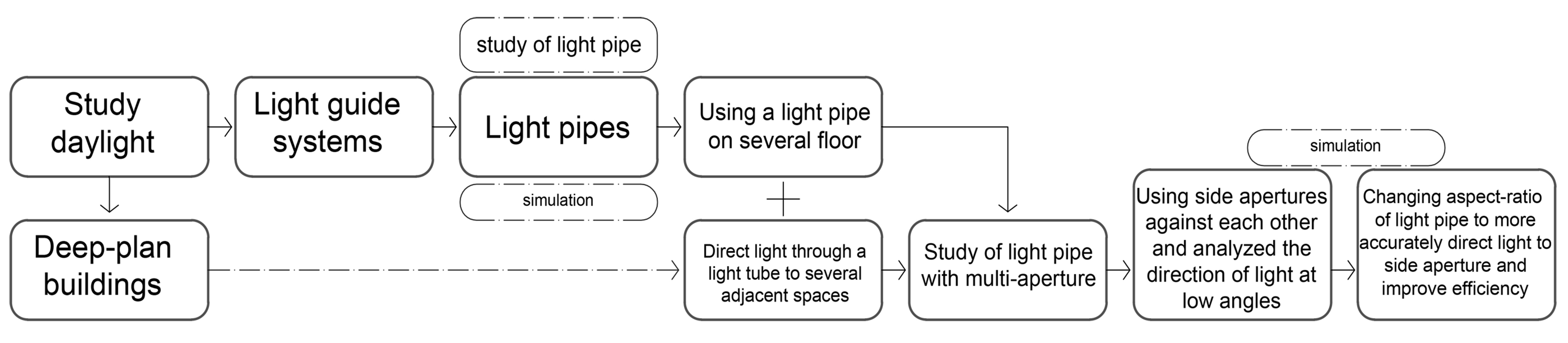
Fig. 2. Flowchart of research formation.
4. Research methodology
This study was performed using computer simulation, generally with the aim of investigates the efficiency of the light transmission system, in the analysis of daylight illuminance efficiency and ray-tracing simulation.
4.1. Software
This study focuses on the daylight analysis of a building modeled in Grasshopper plug-ins, in 3D modeling software Rhinoceros [42]. Grasshopper plugins Ladybug and Honeybee can simulate models for energy and daylight with a variety of recipes [43]. Grasshopper plug-in are designed to control the parameters; when the number of variables is numerous in design and requires a separate 'get run' for each setup, and also the settings have a lot of complexity, the parametric models can be very useful [44]. Ladybug and Honeybee are open source software [45] that provide the ability to read materials, constructions and geometries with using IDF models. Honeybee and Ladybug software for building performance simulation and Energy simulation are based on Open Studio and Energy Plus, and daylighting simulations are based on Radiance and Daysim [46]. The ladybug can import the standard EnergyPlus weather files (EPW) into Grasshopper and display it visually in 3D [47]. The sky is considered, in this simulation, is by using a standard clear sky CIE (Commission Internationale de l’Éclairage), a clear, cloudless sky [48]. Iran has at least 300 [49] clear sunny days in a year and solar radiation is 2200 kW-h per square meter averagely. In fact, most of the year, the sky is clear and cloudless; Therefore, it was necessary to consider a clear sky in the simulation of this study. Standard skies are very realistic to simulate sunlight compared to the general sky [51]. CIE is defined as less than 30% of the cloud, and also direct sunlight is considered [51]; This sky has developed 15 types of skies. Methodology background especially in [52] and [53] show that the best choice for conducting the simulation is “CIE sky”. Therefore, the “standard clear sky CIE’’ is selected for the simulation. We also used the BSDF file [54], in this simulation due to the lack of track light distribution in the RADIANCE. The BSDF file produced by genBSDF can be imported into Window. The BSDF file was used for patch or glazing layers that required to scatter beams light, in fact the diffusers in light output apertures. Computer specifications used in this study is; Intel_ Core i7 processor (2,5 Ghz) 4710 mq, 16 GB RAM, graphics card: NVIDIA quadro_ k3100m (4 GB), OS: Windows_ 7, 64 bit. And Simulation times, is about 3.25 min for each solar altitude angle.
4.2. Case study description
The case study is in Tehran, a city in the north of Iran with the following geographical specifications: 35.416º_ north latitude, 51.15º_ east longitude, and 1190 m of elevation from the sea. The weather information used in this study is from energy plus weather information's (epw) [55]. The characteristics of office rooms in this study are such that each room has four users; that is, four office desks with a height of 80 cm with their accessories (computer and keyboard), are shared into space and each room has a door with width 90 cm and height 220 cm. In office spaces, the level of lighting should have good quality [56], so that office work can be done easily and does not cause eye irritation. Therefore, the radiance properties of the indoor environment must be controlled. Also, height of work-plane should be proportionate to the function of the space; in this study, the standard is office desks (80 cm).
In order to carry out this simulation, a virtual model has been developed, which is a section from an office building that has two floor (first floor and ground floor). The rooms considered for this study (Fig. 3), include three rooms, two room on the first floor and one room on the ground floor. Architecturally, the ceiling of the ground floor room is located exactly between the two upper floors. This three room, are not possible to receive daylight from the façade. One room is on the ground floor named G-room and two rooms are on the first floor named L-room, western room and R-room, eastern room. The ground floor room is located exactly in the middle of the two rooms on the first floor(L and R), so that four light transmission pipes are placed in a line each 1.2 m, passing between the two rooms (L and R) on the first floor and ending on the celling of ground floor(G-room). The rooms on the first floor (L and R), are both the same size. 5 × 5.5 m and 2.7 m height. And ground floor room (G-room) is 5 × 5.5 m and 2.4 m height.
Figure 3
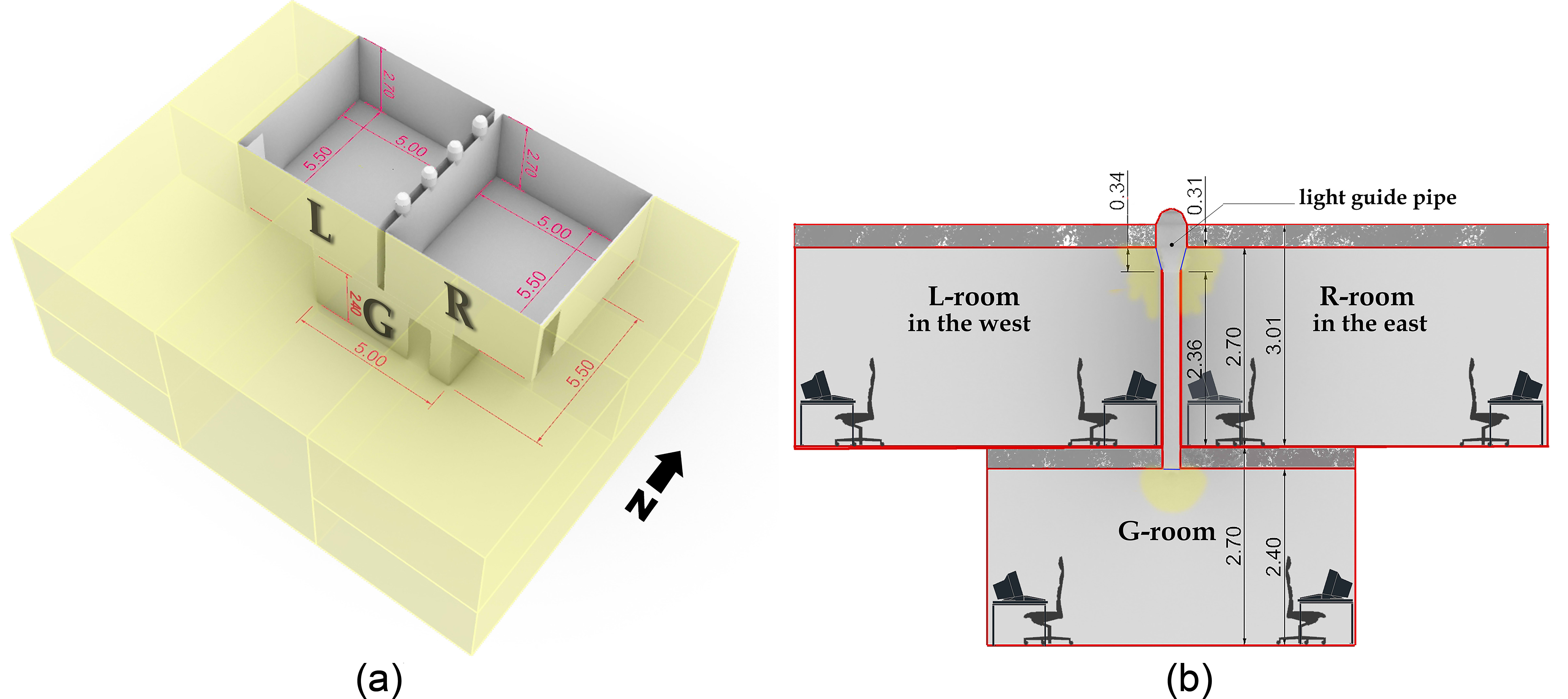
Fig. 3. (a) Isometric image of the case study (b) section of the case study.
4.3. Simulation process
Standardized Radiance specifications of model in this case study as a reference office room are taken from this research [57]. The simulation process was set up as a program, in which the simulator extracted the results at 7, 9, 11, 13, 15, and 17 hours on the 15th of each month (12 months). Recorded results included average illuminance, light distribution pattern, and ray-tracing, which were performed separately for each room for more accuracy. Work plane were placed at a height of 80 cm from the floor for all three rooms to calculate the illuminance and nodes grid size for analysis are 10×10 cm. Radiance materials for all rooms are shown in Table 1 And the input Radiance simulation parameters for this case study are summarized in Table 2.
Table 1
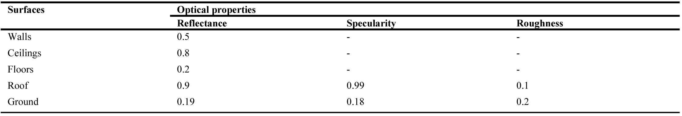
Table 1. Radiance materials for all rooms.
Table 2

Table 2. Radiance simulation parameters.
4.4. Modeled light pipe description
Light pipes model presented in this paper consisted of three components; a pipe with a high reflection coefficient, a diffuser for the distribution of light that is installed interior space and a collector located in the external environment. The main functions of collector are to collect daylight and prevent precipitation and dust from entering the pipe. This light pipe, has multi-aperture, so that the two-side aperture are face-to-face each other and an aperture at the bottom of the pipe. Also, this light pipe consists of several pipe with different diameters, in fact it is a multi-aspect ratio light pipe. Diameter of the opening at the beginning of the pipe is 44 cm and the end of the pipe has a diameter of 26 cm (Fig. 4). The side apertures were placed in the distance between the wide pipe and the narrow pipe, which has a semi-conical shape and makes it easier for light to pass into the pipe depth. The side apertures are cut from body of the semi-conical pipe, for this reason, they have made an angle of about 14 degree to the vertical line, and they have come out of the inner wall. This angle not only makes it easier for penetrating light to pipe depth, it also emits light into the room, somewhat vertically on the floor. The light tube presented by this study is a development and innovation in the field of light transmission devices, which in terms of form, its previous example is not available in any study. The relationship between the dimensions and size of its various parts is more in terms of the executive details of the construction in Iran; Iran Construction Engineering Organization (IRCEO). In fact, the diameter of the pipe is proportional to the thickness of the wall with its joinery. The doubling of the diameter of the pipe near the ceiling and the connection of these two members, as well as the easier passage of light, determined the angle between the diameter of the wide pipe and the narrow pipe.
Figure 4
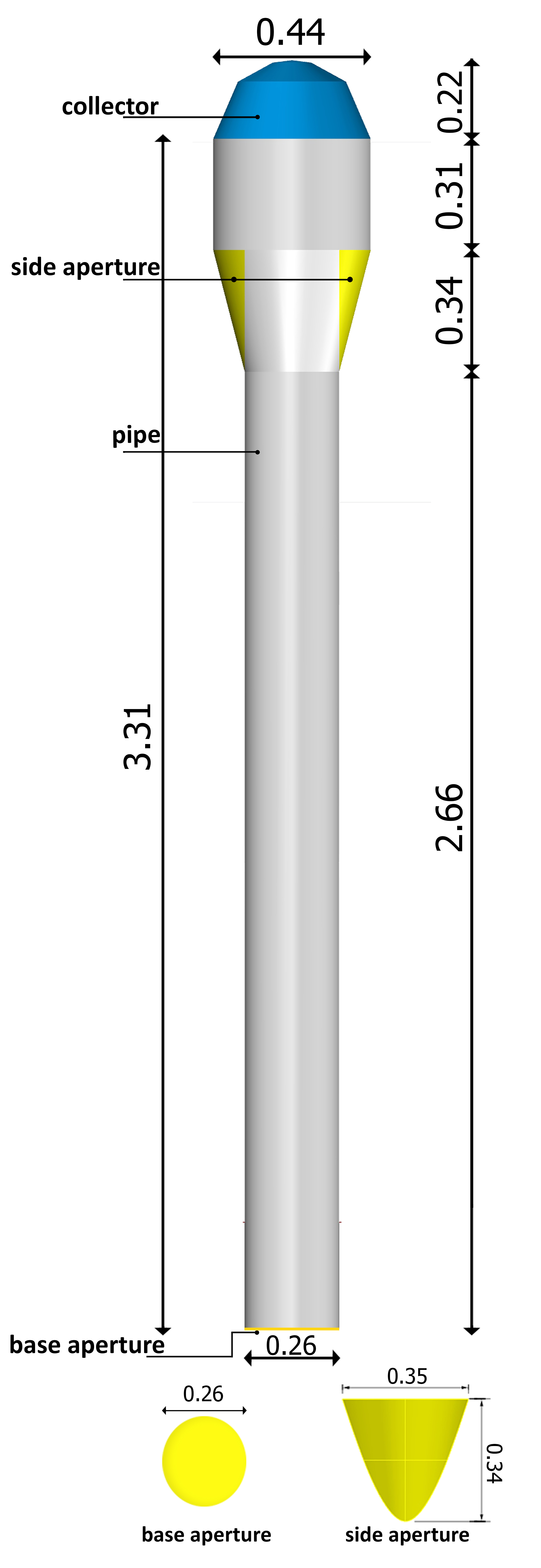
Fig. 4. (a) Light pipe (M-type) specifications used in case study, (m).
The rooms at the first levels (L-room – R-room) receive light from side apertures and the ground floor receives the light from an aperture installed to the base of the light-pipe.
The materials used for these pipes are made of an aluminum film with a reflection coefficient of 0.98 this feature is used in the inner layer of the pipe. Area of each aperture; side apertures are 0.085 square meters and base aperture, is 0.054 square meters, and transparent cover-diffuser on the apertures with 58%light transmittance and 2mm thickness. There is no significant change in the relationship between area of apertures and illuminance [34]; In other words, changes in the area of side aperture do not have much impact on base aperture illuminance. Outer dome, has a diamond shape is Polymathic Methacrylate (PMMA) with 92% light transmittance. A diamond-shaped dome for the collector captures more light than a simple dome and this was proved in this study [58]. Also a comparison between the flat and crystal dome collectors, which is done by M. Sibley and A. Peña-García [59]; The crystal dome allows transmit a higher luminous flux than a flat glass in the colder months of the year (winter), this rate increases even more; As a result, the crystal dome performs better than flat glass, especially when pollution and effects of weathering are involved in the analysis, moreover for this crystal dome cover, antireflective glass with a high transmittance coefficient is recommended. Radiance properties of materials for light pipes in our case study are shown in Table 3.
Table 3

Table 3. Radiance properties of materials for light pipes.
Jenkins, D and Muneer, T [60] have described the relationship between the input luminous flux of light pipe and the output luminous flux with numerical calculations And also explained when, ratio of length of pipe to its diameter increases (so-called aspect-ratio), the amount of output light decreases, and conversely, as the length of the pipe decreases relative to the diameter, the amount of output light increases. Now, we find that if the length of the pipe is less than its diameter, the loss of reflection event on their path is less. Obviously, the number of reflections depends on the length of the pipe, so the shorter the length of the pipe, the less light beams is reflected.
As mentioned, model presented in this study(M-type), has multi- aspect ratio; wide opening at the top of the light pipe with ratio(dimeter/length) 1:2 approximately and narrow pipe with 1:10 and semi-conical shape is on average 1:1. In addition for estimating the number, dimensions and areas of light pipe, can be used illuminance reference criterion, which is pre-determined for each space with different uses, and can provide confidence in terms of physical characteristics. David M. Kennedy and some of studies explain the relation between scaled model of light pipe and illuminance and lux range recommended (illuminance reference), 500 lux range recommended for office illuminance [22,34,61]. In addition, in this research, for the most optimal geometry, light pipes in terms of aspect-ratio, suggest a ratio of 1 to 10 And this ratio is allowed up to 1 to 20, but the amount of light transmittance is very small. Also, pipes with a diameter of less than 20 cm should be avoided [24].
5. Results and discussion
5.1. Ray tracing simulation study for light pipes
The collision of incident light on the opening of the pipe at different angles can be very decisive in the loss of reflections. The incidence of rays depicted at middle angles (About 40° to 60°) [62]; This research, explained that the first incidence of rays on the pipe, covers 40% of the length of the pipe. In this regard, the importance of incident light at low and medium angles at the beginning of the light pipe is very high and the number of light reflections depends on the diameter of the tube and Also, the number of reflections inside the pipe determines the light beams loss; that approximately rays loses 5% of its light beams intensity after each reflection.
Ray tracing Simulation in our case study presents by Ladybug-honybee, that compared in tow-types of light pipes. The simulation program for both tubes in equal conditions on one day was analyzed, angles were selected that were reminiscent of the movement of the sun in one day. In fact, 5 samples of angles. The first type of light pipe used in this case study, with a wide opening at the top of the pipe ( M-type) and the second type of straight and simple light pipe (S-type) , both of which have tow side apertures above the pipe, and the same radiance materials. However that one of the advantages of light pipes is that they are efficient, regardless of the orientation of the building, but by passing the light through the light pipe used in simulated model with multi-aspect ratio, it can be concluded that the direction of light coming out of the apertures is completely affected by the changing solar altitude angle. As the opening widens at the top of the light pipe (M-type), at low altitude angles, the number of light reflections decreases so that light can pass through the aperture and enter the space. Now if the wide opening, its diameter is reduced toward the narrow pipe, the number of reflections will increase (Fig. 5). Decreasing the pipe diameter, increases the number of reflections, then the more the number of reflections inside light pipe, light beams intensity will decrease, and finally less light enters the space.
Figure 5
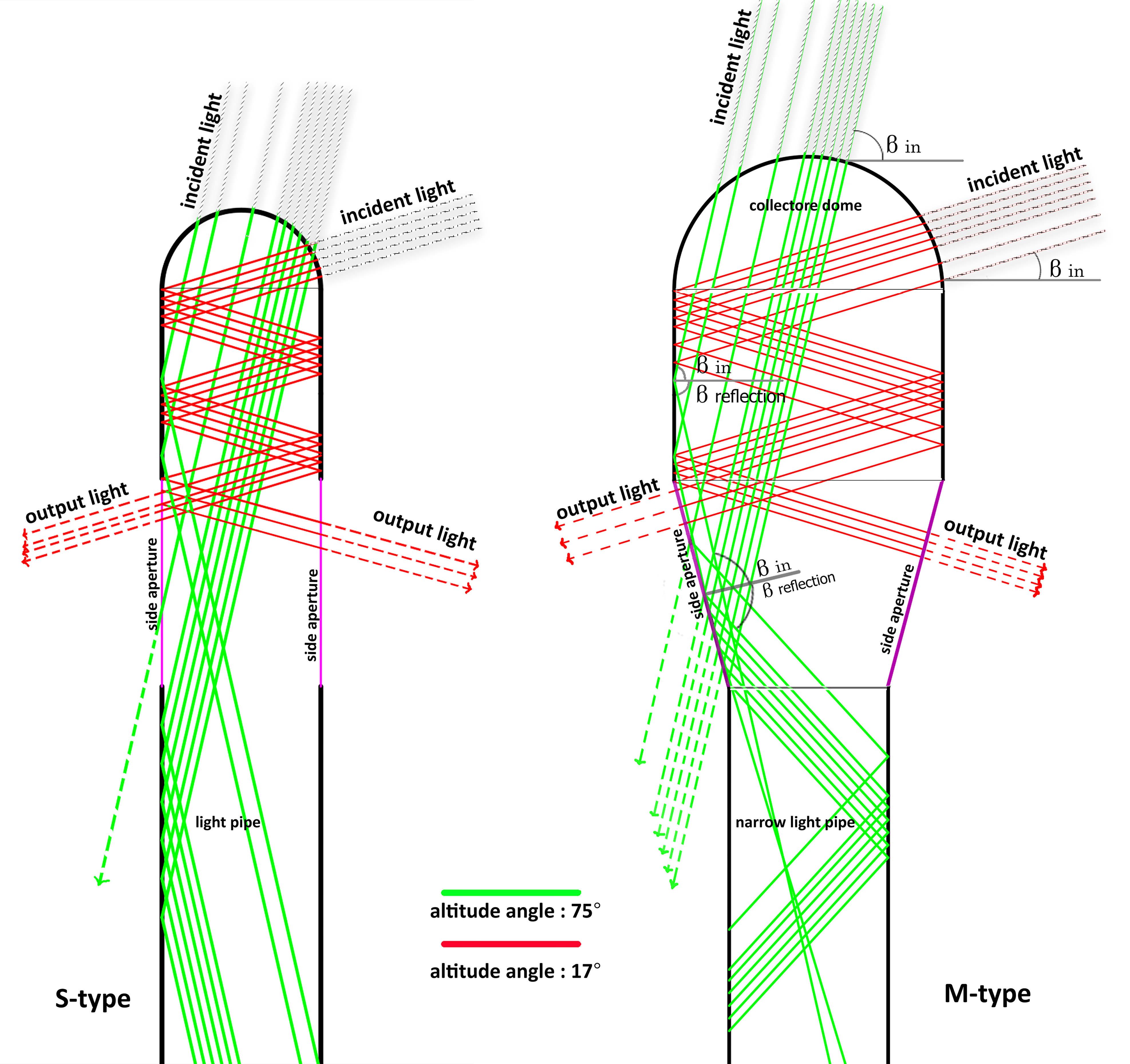
Fig. 5. Schematic representation comparison how light passes and the number of reflections inside the tube of two-types of light pipes in the incidence of tow rays with different angles.
The side apertures in the M-type, which has a 14º angle to the vertical, which causes the light radiation at close to vertical angles, in addition to being easier to transfer to the depth, but also some light enters the room directly from the side apertures.
By comparing these tow-types of light pipe at equal altitude angles in this (Fig. 6), the penetration of light beams in each type is different. In general, light pipe of S-type have more light penetration to depth, and especially at mid-altitude angles, it emits more light beams to depth than the M-type, but light pipe with wide openings (M-type) at low altitude angle, emit more light beams to side apertures. Also, the light pipe with the wide opening at near-vertical altitude angles (90º), distributes light beams more evenly between the all apertures and also emits more light beams into space from the side aperture, non-reflectively (direct).
Figure 6
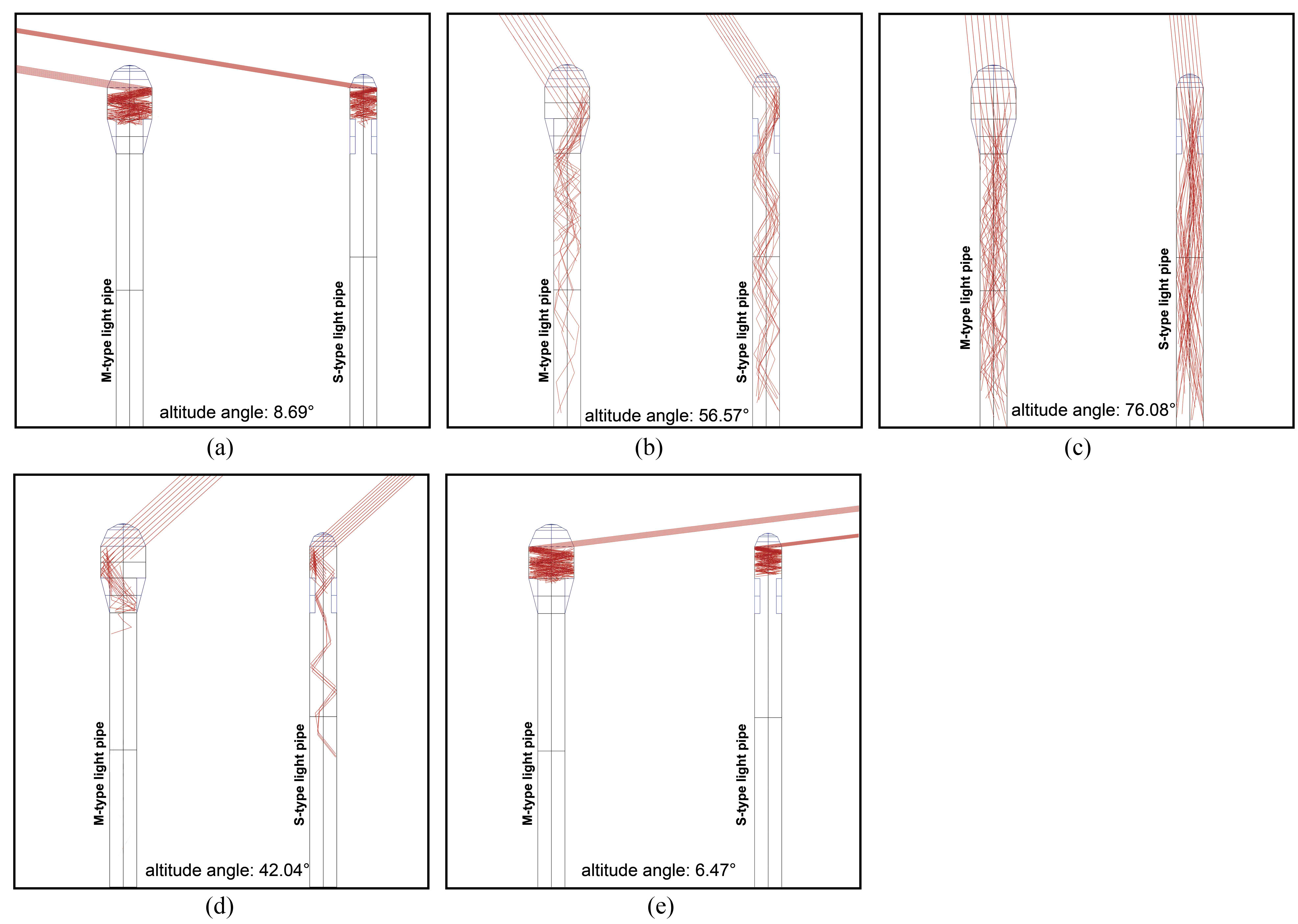
Fig. 6. (a-e) Ray-tracing comparison of tow-types of light pipes in penetration of light beams; In the S-type light pipe, at mid-angles, the inner reflections of the pipe extend deeper but, at low angles, the S-type has more reflections than the M-type And loses more light.
5.2. Light pipes efficiency
To calculate the amount of illuminance received, it is preferable to use a fixed simulation, not dynamically, because in dynamic simulation it is not possible to record the peak of the illuminance and at least the illuminance at certain times. According to Grid Base Simulation, there were four variable parameters in this comparison (Hours, Months, Location of rooms and the direction of the light entering the rooms from apertures), and the effect of these variables on each other was analyzed and compared. In Table 4, these parameters are specified in the category. The choice of these hours is due to the fact that when multiplied by 12 months of the year, it can cover a maximum of different altitude and azimuth angles in a year.
Table 4
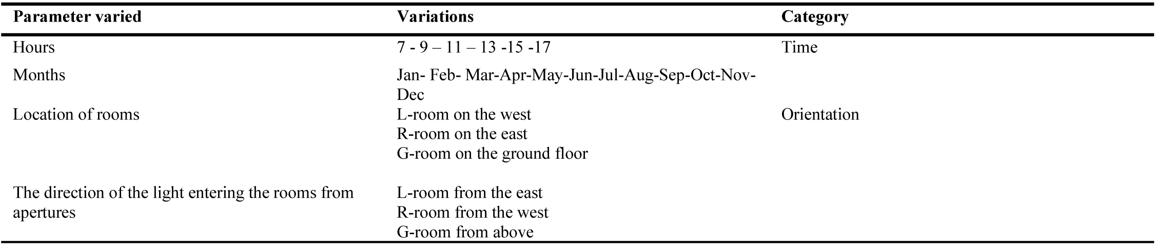
Table 4. Varied parameters and category.
7 and 17 o'clock simulate the lowest elevation angle of the sun, 11 and 13 o'clock cover the angles close to the vertical, and the hours between 9 to 11 o'clock and 13 to 15 o'clock simulate the mid-angle.
In the diagrams shown in the Fig. 7, the illuminance of each room is calculated every fifteenth of each month, which shows the minimum and maximum illuminance in the middle of each month in each month in the vertical column of diagrams. In each diagram between the tow-type of light pipes (M and S), the information of the illuminance is compared. In the diagrams of the first-floor rooms (L-room, R-room) in January, February, March, October, November and December, the efficiency of both pipes is almost the same. With a change in the aspect ratios of the light pipe (M-type) of this study at one-fifth the height of the top of the pipe (In fact, length 65 cm has doubled the diameter of the pipe), This means that increasing the diameter at the top of the pipe, due to its relatively small change, not only increases the amount of illuminance in all three rooms, this change in the light pipe system with side apertures can more accurately reflect light rays to the desired point. However, in the previous section 5.1 we explained that a simple pipe (S-type) performs relatively better in terms of light transmission to depth, but with the significant increase in the efficiency of wide-light pipe (M-type) on the ground floor (A-room), it can be inferred that with such a change in the opening of the pipe, a very good performance can be achieved.
Figure 7
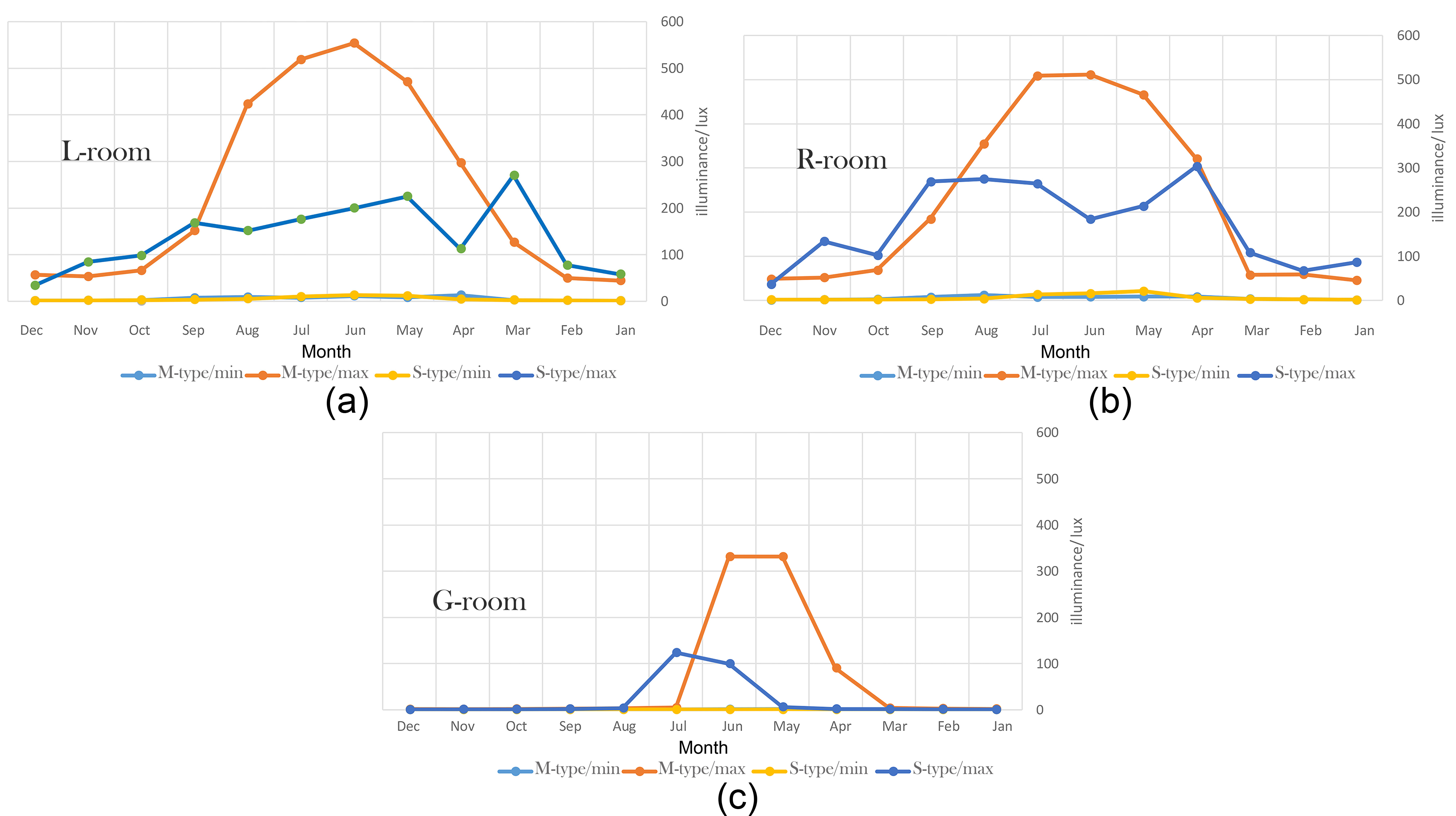
Fig. 7. Comparison of efficiency between two-types of light pipes in all rooms that is calculated on average in the middle of each month.
5.3. Distribution of light
Based on the explanations in the previous sections, we found out how the change in the diameter of the opening at the top of the light pipe and placement of the apertures affect the improvement of the reflection of light to the desired point in the side apertures. The diagrams presented in Figs. 8 and 9 show the pattern of light distribution in the rooms. All three rooms with tow-types of light pipe (M-type, S-type) are typically simulated from tow-different altitude angle and azimuth angle (Al 40.71º, Az 109.74º and Al 73.13º Az 227.79º). The choice of these angles is based on the fact that the models are analyzed both at a low altitude and near-vertical altitude angle. Also, the effect of light distribution on both high and low altitude and with an azimuth should be determined to show the sun on both the left and right sides of the building.
Figure 8
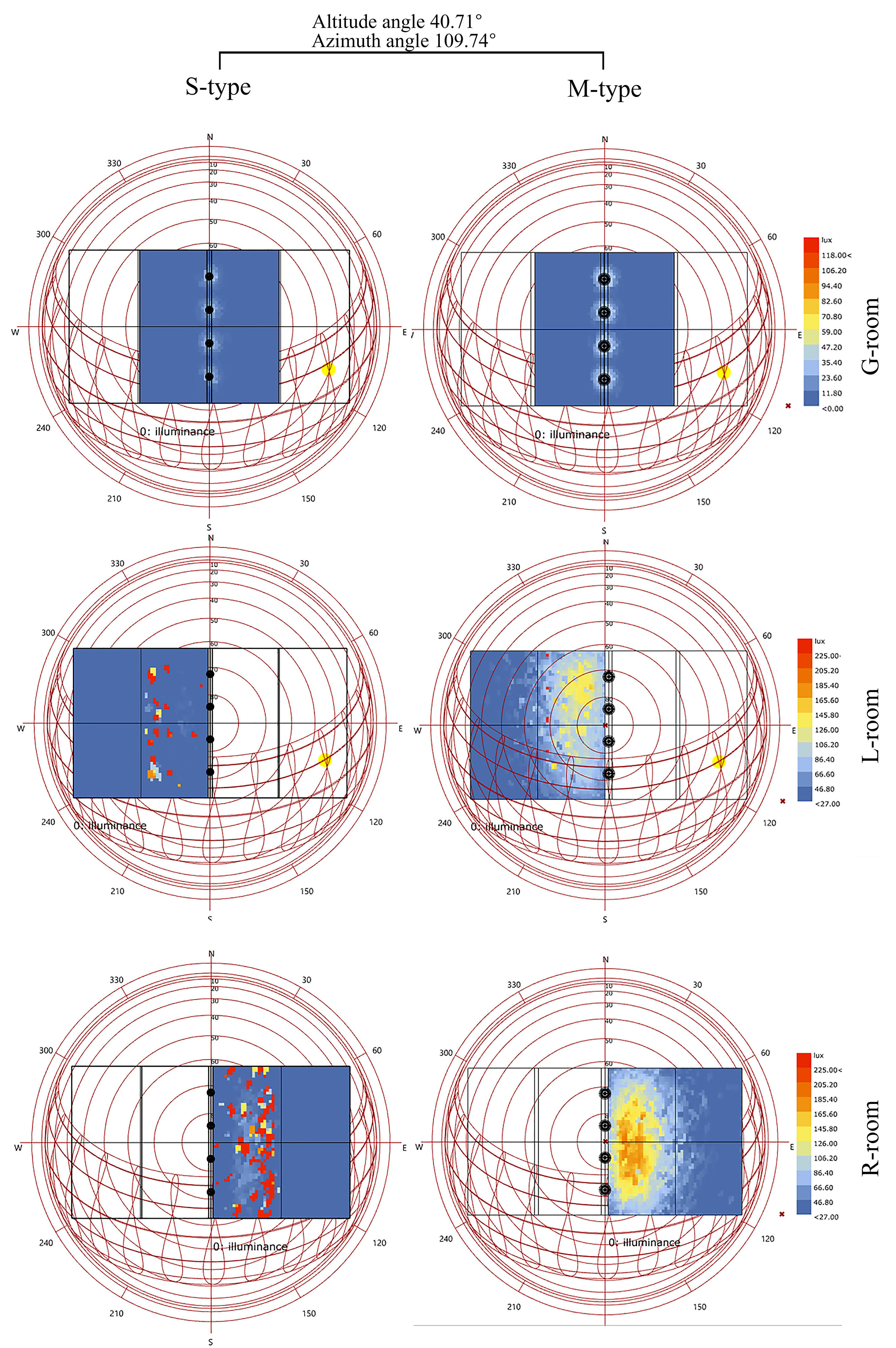
Fig. 8. Comparison of distribution of light between tow-types of light pipes in all rooms, in the altitude angle of 40.71º and azimuth angle of 109.74º.
Figure 9
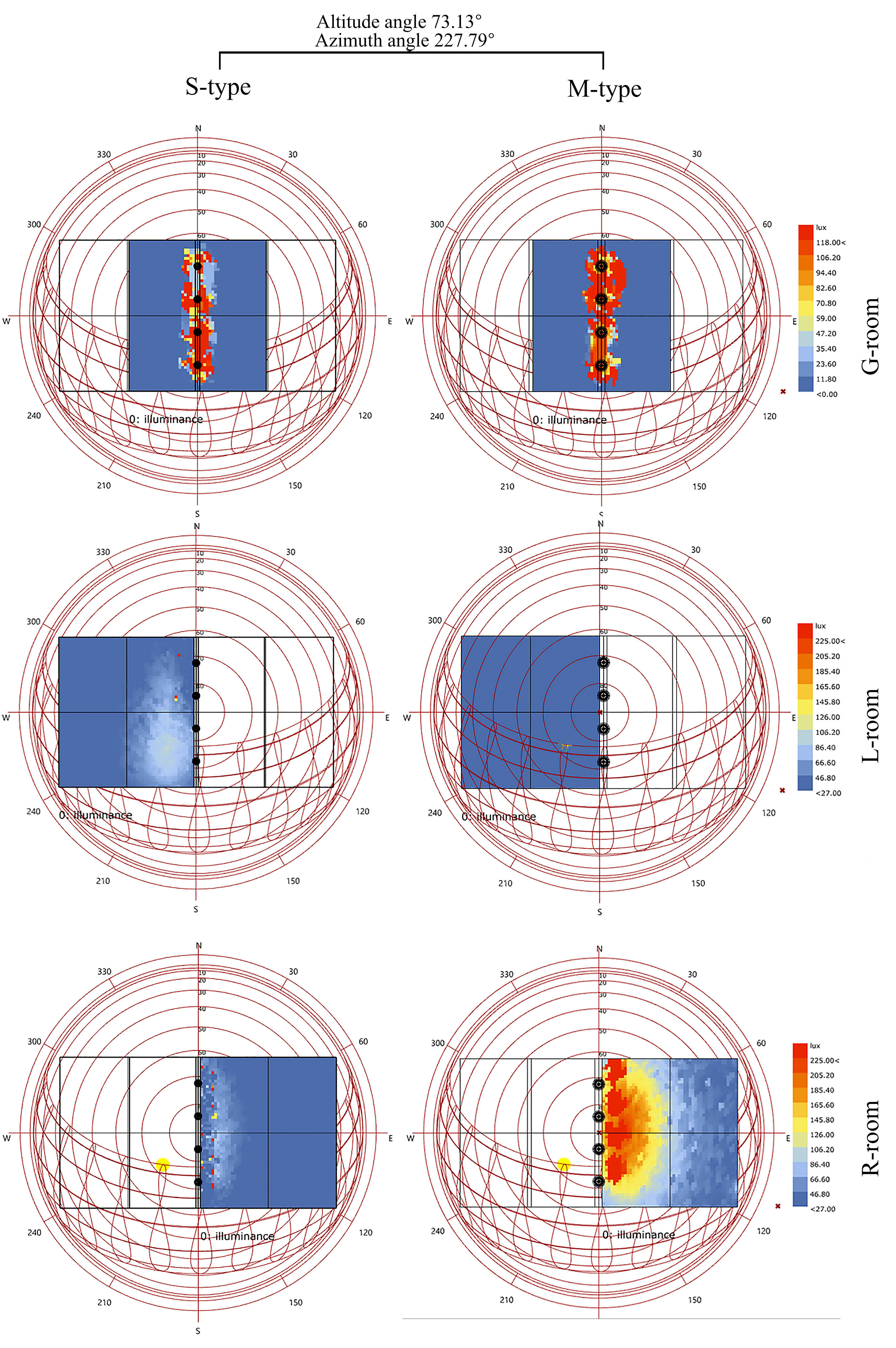
Fig. 9. Comparison of distribution of light between tow-types of light pipes in all rooms, in the altitude angle of 73.13º and azimuth angle of 227.79º.
Due to the equal area of the apertures and the use of one type of glass-diffuser with equal specifications in both types of light pipe; from this simulation, it can be seen that the M-type light pipe, although its side aperture has a 14º angle to the vertical, but, it is more desirable to transmit light to the end of the room as well as to distribute light at room's floor at mid to low altitude angle, 40.71º Fig. 8. As shown in the light distribution pattern at an altitude angle close to vertical 73.13º Fig. 9; it can be seen that due to the oblique side aperture on the first floor, light enters almost one of the rooms completely and at the same time in the adjacent room, very little light reaches the room. In a ground floor room, the light distribution does not depend on the altitude and azimuth angel, and only the amount of illuminance changes; because, firstly, the aperture of the ground floor (G-room) is horizontal and secondly, the light reflects a lot after passing a long path of the tube.
5.4. Amount of illuminance for case study (M-type light pipe)
In the previous sections 5.2, efficiency of the tow-types of light pipe was compared. In Tables 5, 6, and 7 the amount of average illuminance in each room is measured separately; From 7 am to 5 pm in 12 months of the year. Approximately the maximum number of illuminance in all three rooms is calculated in five months in the middle of year. The amount of illuminance for each room, considering illuminance reference of the office room, reaches between 400 to 500 lux in some times of the year. The amount of illuminance received was compared between the tow-types of light pipe at low altitude angle, and M-type had a better performance. According to Table 5, which is for L-room, the amount of illuminance has increased relatively at 1 pm, when the solar altitude angle in closer to the vertical than any other time of the month, It has been observed that as the altitude increases to 75º (Maximum altitude angle of the sun in this location), the illuminance decreases, and as the altitude angle decreases, the illuminance gradually increases; and this is true for both rooms on the first floor Table 6. At mid-altitude angle (between 40º and 60º), maximum illuminance is seen at 9 am to 11 am in the L-room, and at 1 pm to 3 pm in the R-room; this is due to the widening of the pipe opening as well as the oblique aperture, which allows light beams to pass directly through the aperture without reflection.
Table 5
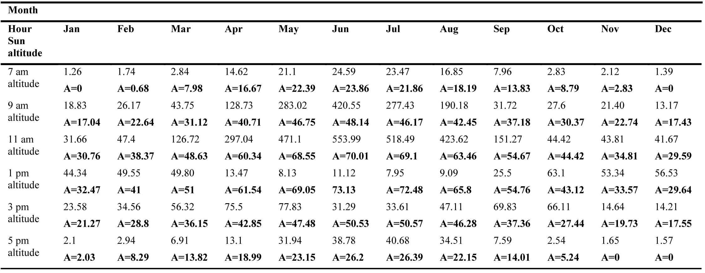
Table 5. Amount of illuminance for L-room.
Table 6
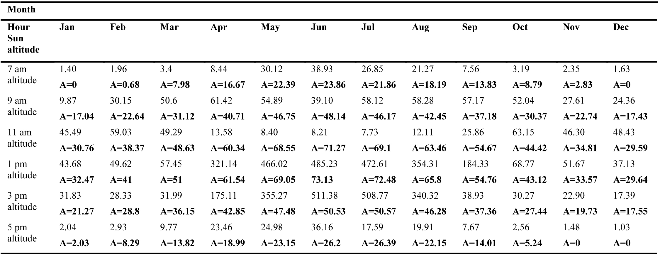
Table 6. Amount of illuminance for R-room.
Table 7
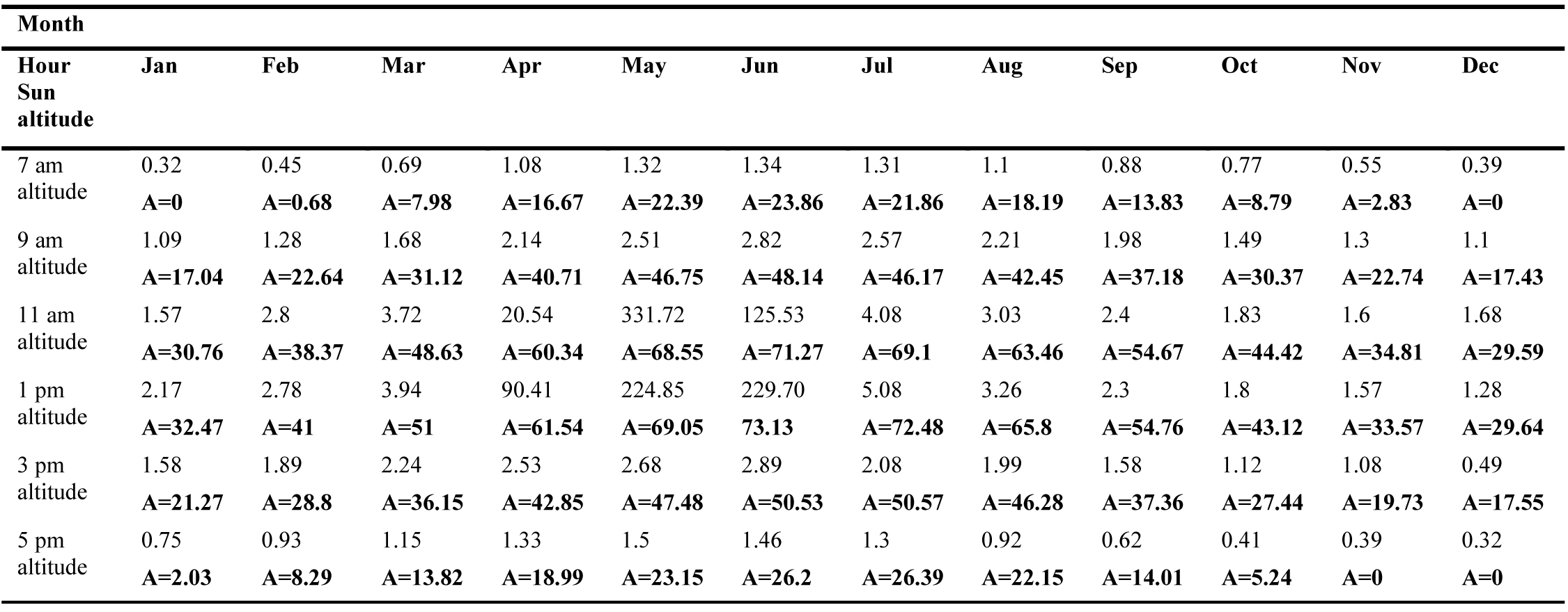
Table 7. Amount of illuminance for G-room.
Table 7 also calculates the amount of illuminance for the ground floor. When the angle of the altitude angle reaches near the vertical angle, the amount of illuminance reaches its maximum.
In Section 5.1, by Comparing the two types of light pipes in the Ray-tracing simulation, the light pipe S-type performed better in penetrating light, but it should be noted that the efficiency or the amount of illuminance in the M-type light pipe, is higher; This is due to the increase in the diameter of the opening at the top of the pipe. In the simulation, it was found that the maximum illuminance in both tubes occurs at high altitude angles. And the acceptable amount of illuminance in a room that receives light from the base aperture involves a small amount of time during the day.
5.5. Relationship between illuminance and sun azimuth angle
The following Fig. 10 shows the relationship between solar azimuth angle, altitude angle and the direction of light reflected in the light pipe. This analysis was conducted in the three months of June, July, September at 7, 9, 15 and 17 o'clock, in order to cover almost most of the azimuth and altitudes in the comparison of rooms. In this figure, it can be seen that low altitude angle, at 7 am and 5 pm (when the sun's azimuth is close to 90 and 270º), the sun's rays are almost perpendicular to the surface of the side aperture, as a result, most of sun's rays after entering the inside of light pipe enters a room that receives light from the opposite direction to the sun's rays. As the altitude angle remains constant and the azimuth angle increases (when the light beam directed along the side apertures), it is observed that the altitude angle of reflection of incident light inside the light pipe is disturbed and is not reflected towards the apertures as before mood.
Figure 10
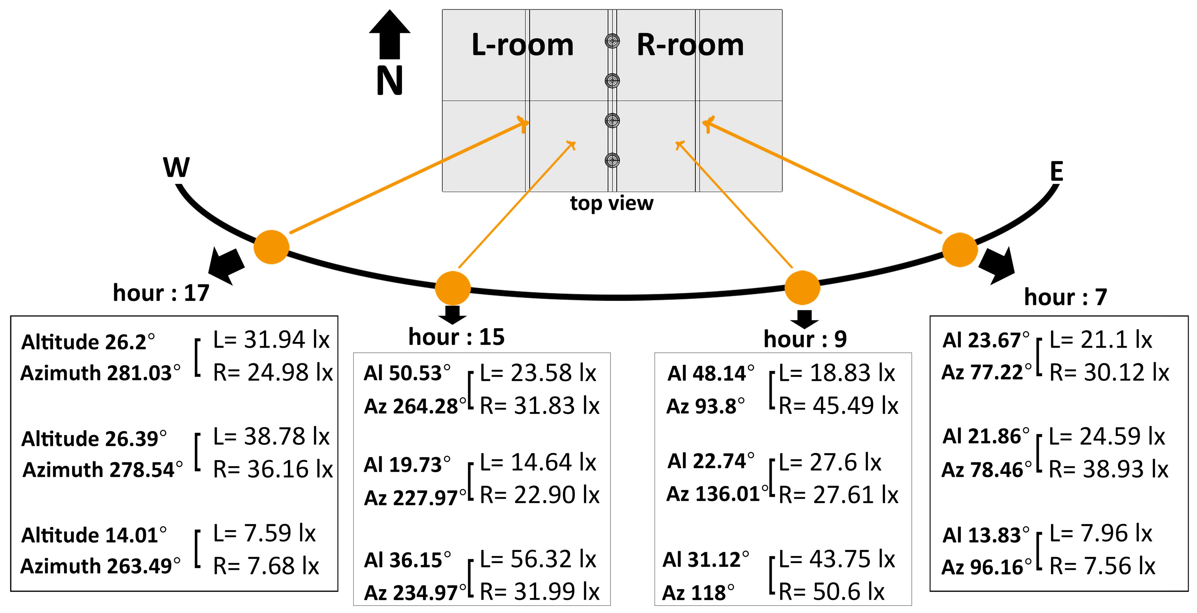
Fig. 10. Relationship between sun's azimuth angle, altitude angle and the direction of reflected light in the light pipe (M-type).
6. Conclusions
As we know, one of the advantages of light pipes is that they can be used regardless of the orientation of the building. In this paper, we observed the simultaneous effect of a light transmission pipe with several apertures and the widening of the upper opening of the light pipe, as a result, an light pipe with side apertures, the amount of illuminance and time of the peak of the illuminance, is completely influenced by the solar altitude angle. Also, the light entering the rooms at low altitude angles relative to the side apertures is contrary to the direction of sunlight; in the other word the light beams is reflected to the aperture, which is located opposite the sunlight. With the increase in the diameter of the pipe opening, the efficiency of light increased by about 2 times compared to straight pipes (S-type). However, it was relatively weaker in guiding the light to the depth of the pipe, but in general, it had a great effect on the amount of light received. In this paper, by simulating a daily in twelve months of the year, it can be seen that the optimal efficiency of light pipes in most times of the day, is much less than the amount of illuminance required for rooms. However, the light transmission pipe has always been used in combination with electric lighting, and has helped reduce the consumption of electrical load.
According to Tables 5, 6, and 7, it can be inferred that a common light pipe system, for several rooms, is quite different in efficiency during the day for each room, and can't expect efficiency to be equal for rooms at the same time Fig. 11. As a result, the function of building and the time of use of the rooms with the peak times of efficiency should be considered, so that the system can be used optimally.
Figure 11
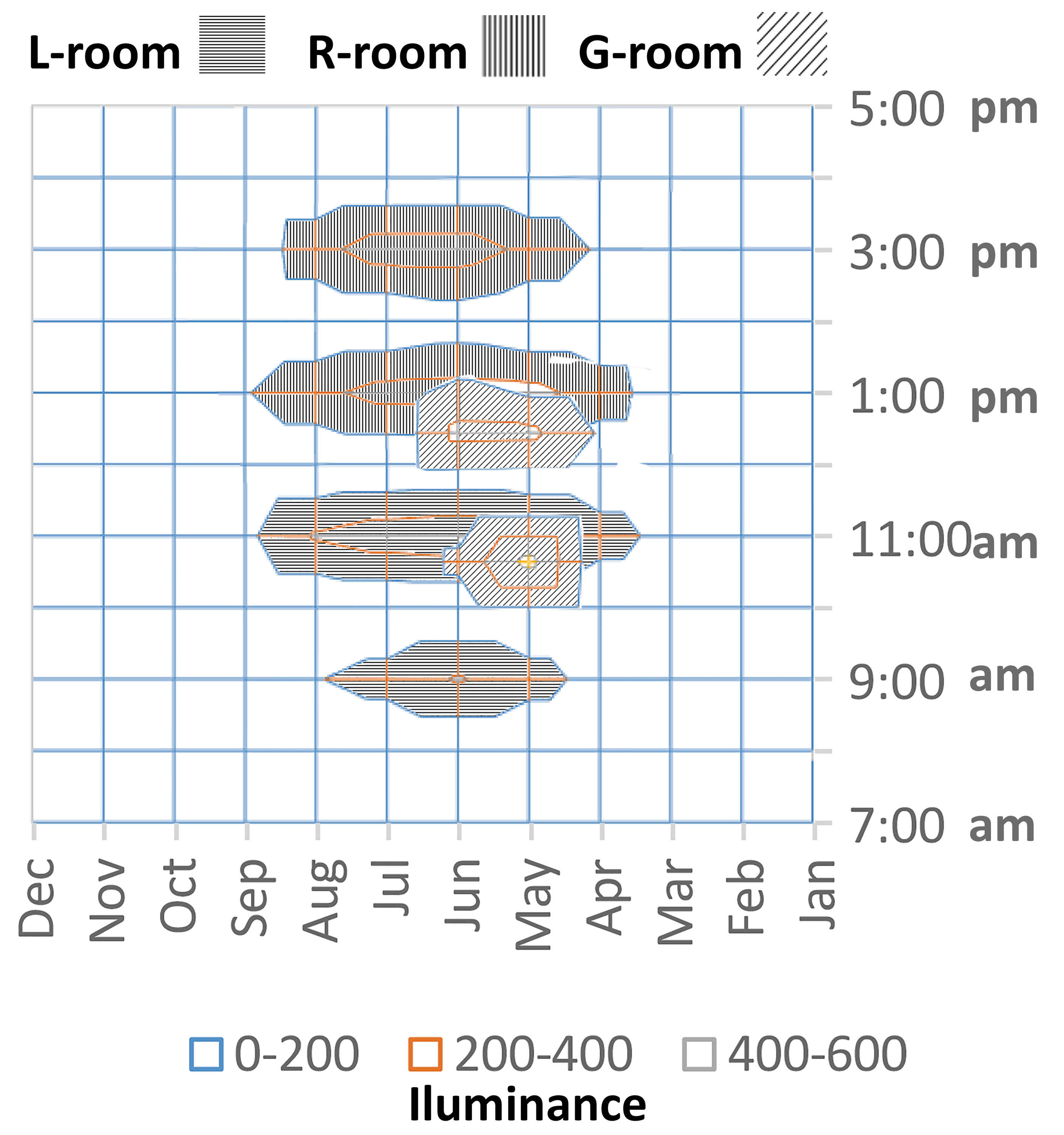
Fig. 11. The average illuminance of light pipe (M-type), for all rooms (L-room, R-room, G-room).
Acknowledgement
The authors gratefully acknowledge the scientific support from the Department of Architecture & High performance Architecture Laboratory, Tarbiat Modares University. We also thank Dr. Mansour Yeganeh and Dr. Peiman Pilechiha for support in carrying out this research.
Contributions
All authors contributed equally in the preparation of this article.
Declaration of competing interest
The authors report no conflicts of interest. The authors alone are responsible for the content and writing of this article.
References
- M. Hn, N. A. Rm, J. Sj. n, A. B. M .A. Mk, A. Nr, Global prospects, progress, policies, and environmental impact of solar photovoltaic power generation, Renewable and Sustainable Energy Reviews 41 (2015) 284-297. https://doi.org/10.1016/j.rser.2014.08.046
- K. H. Solangi, M. R. Islam, R. Saidur, N. A. Rahim, H. Fayaz, A review on global solar energy policy, Renewable and Sustainable Energy Reviews 15 (2011) 2149-2163. https://doi.org/10.1016/j.rser.2011.01.007
- F. Sharp, D. Lindsey, J. Dols, J. Coker, The use and environmental impact of daylighting, Journal of Cleaner Production 85 (2014) 462-471. https://doi.org/10.1016/j.jclepro.2014.03.092
- Abdeen MustafaOmer, Energy, environment and sustainable development, Renewable and Sustainable Energy Reviews 12 (2008) 2265-2300. https://doi.org/10.1016/j.rser.2007.05.001
- Mohammed Mayhoub, Cleaning innovative daylighting systems: Economic assessment, 153 (2017) 63-71. https://doi.org/10.1016/j.enbuild.2017.06.074
- P J. Littelfair, M. E. Aizlewood, A. B. Birtles, The Performance of Innovative Daylighting Systems, Renewable Energy 5 (1994) 920-934. https://doi.org/10.1016/0960-1481(94)90113-9
- H. F. O. Muller, Prof. Dr. Ing , Application of Holographic Optical Elements In Buildings For Various Purposes Like Daylighting, Solar Shading And Photovoltaic Power Generation, Renewable Energy 5 (1994) 935-941. https://doi.org/10.1016/0960-1481(94)90114-7
- L. O. Beltrán, E. S. Lee, S. E. Selkowitz , Advanced Optical Daylighting Systems: Light Shelves and Light Pipes, Journal of the Illuminating Engineering Society 26 (1997) 91-106. https://doi.org/10.1080/00994480.1997.10748194
- S. Varga, A. C. Oliveira, Ventilation terminals for use with light pipes in buildings: a CFD study, Applied Thermal Engineering 20 (2000) 1743-1752. https://doi.org/10.1016/s1359-4311(00)00005-3
- S. Darula, M. Kocifaj, J. Mohelníková, Hollow light guide efficiency and illuminance distribution on the light-tube base under overcast and clear sky conditions, Optik - International Journal for Light and Electron Optics (2013) 3165– 3169. https://doi.org/10.1016/j.ijleo.2012.09.052
- D. Jenkins,T. Muneer, Modelling light-pipe performances—a natural daylighting solution, Building and Environment 38 (2003) 965–972. https://doi.org/10.1016/s0360-1323(03)00061-1
- S Pleshkov, G Brakale, I Vedishcheva, A Project Aimed to Increase Energy Efficiency of the Object Swimming Pool Universitetsky by Application of Hollow Mirrored Tubular Light Guides Under Trade Mark, IOP Conference Series: Materials Science and Engineering 463 (2018) 042050. https://doi.org/10.1088/1757-899x/463/4/042050
- C. Baglivo, M. Bonomolo, P.Maria Congedo, Modeling of Light Pipes for the Optimal Disposition in Buildings, Energies 12(2019) 4323. https://doi.org/10.3390/en12224323
- E. Brembilla, D. A. Chi, C. J. Hopfe, J. Mardaljevic, Evaluation of climate-based daylighting techniques for complex fenestration and shading systems, Energy and Buildings 203 (2019) 109454. https://doi.org/10.1016/j.enbuild.2019.109454
- M. Mahdavinejad, M. Bemanian, S. Matoor. Estimation performance of horizontal light pipes in deep-plan buildings, case study: Tehran office buildings. Honar-Ha-Ye-Ziba: Memary Va Shahrsazi (2013): 41-48.
- H. Wachenfelt, V. Vakouli, A. Pacheco Diéguez, N. Gentile, M. Dubois, K. Jeppsson, Lighting Energy Saving with Light Pipe in Farm Animal Production, journal of daylighting 2 (2015) 21-31. https://dx.doi.org/10.15627/jd.2015.5
- G. Oakley,S.B Riffat, L. Shao, Daylight performance of lightpipes, Solar Energy 69 (2000) 89-98. https://doi.org/10.1016/s0038-092x(00)00049-9
- M. S. Mayhoub, D. J. Carter, The Costs and Benefits of Using Daylight Guidance to Light Office Buildings, Building and Environment, 46(3) (2011) 698-710. https://doi.org/10.1016/j.buildenv.2010.09.014
- V. Burmaka, M. Tarasenko, K. Kozak, L. Omeiza, N. Sabat, Effective Use of Daylight in Office Rooms, journal of daylighting 7 (2020) 154-166. https://dx.doi.org/10.15627/jd.2020.15
- DJ. Carter, The measured and predicted performance of passive solar light pipe system, Lighting Research & Technology 34 (2002) 293–298. https://doi.org/10.1177/136578280203400113
- I.R. Edmonds, G.I. Moore, G.B. Smith, P.D. Swift, Daylighting enhancement with light-pipes coupled to laser-cut light-deflecting panels, Lighting Research & Technology 27 (1) (1995) 27–35. https://doi.org/10.1177/14771535950270010101
- L. Shao, A.A Elmualim, I. Yohannes, Measurement and Modelling of Light pipe for Energy Efficient Lighting, Proceedings of the CIBSE National Lighting Conference, Chartered Institute of Building Services Engineers Lancaster University UK (1998) 410-419.
- A. Diéguez, N. Gentile, H. Wachenfelt, M. Dubois, Daylight Utilization with Light Pipe in Farm Animal Production: A Simulation Approach, journal of daylighting 3 (1016) 1-11. https://dx.doi.org/10.15627/jd.2016.1
- J. Mohelnikova, Tubular light guide evaluation, Building and Environment 44 (2009) 2193–2200. https://doi.org/10.1016/j.buildenv.2009.03.015
- L. Shao, A.A. Elmualim, I. Yohannes, Mirror lightpipes : Daylighting performance in real buildings, Lighting Research & Technology 30(1) (1998) 37-44. https://doi.org/10.1177/096032719803000106
- S Jin Oh, W Chun, S B.Riffat, Y I Jeon, S Dutton, H J Han, Computational analysis on the enhancement of daylight penetration into dimly lit spaces: Light tube vs. fiber optic dish concentrator, Building and Environment 59 (2013) 261-274. https://doi.org/10.1016/j.buildenv.2012.08.025
- K. Vasilakopoulou, D. Kolokotsa, M. Santamouris, I. Kousis, H. Asproulias, I. Giannarakis, Analysis of the experimental performance of light pipes, Energy and Buildings 151, 15 (2017), 242-249. https://doi.org/10.1016/j.enbuild.2017.06.061
- W. Yanpeng, J. Rendong, L. Deying, Z. Wenming, M. Chongfang, Experimental investigation of top lighting and side lighting solar light pipes under sunny conditions in winter in Beijing, Proceedings of SPIE The International Society for Optical Engineering 7157 (2009). https://doi.org/10.1117/12.811992
- E. Mushtaha, B.A. Kana’an, R.A. Al-Jawazneh, R.S. Hammad, Effect of using different light pipe parameters on the daylight quality in buildings: the case of Jordan, Int. J. Green Energy 3 (2016) 1590–1598. https://doi.org/10.1080/15435075.2016.1212354
- G.Y. Yun, H.Y. Shin, J.T. Kim, Monitoring and evaluation of a light-pipe system used in Korea Indoor and Built Environment. 9 (1) (2010) 129–136. https://doi.org/10.1177/1420326x09358007
- N. Ekren, S. Gorgulu, An investigation into the usability of straight light-pipes in Istanbul, Energy Education Science and Technology Part A: Energy Science and Research 30 (1) (2012) 637–644.
- M. Paroncini, B. Calcagni, F. Corvaro, Monitoring of a light-pipe system, solar energy 81 (2007) 1180–1186. https://doi.org/10.1016/j.solener.2007.02.003
- Zastrow, A., Wittner, V, Daylighting with Fluorescent concentrators and highly reflective silver coated plastic films: A new application for new materials, Proceeding of the 3rd Symposium on Optical and Optoelectronic Applied Sciences and Engineering 653 (1986) 93-100. https://doi.org/10.1117/12.938314
- D. M. Kennedy, F. O’Rourke, Experimental analysis of a scaled, multi-aperture, light-pipe, daylighting system, Solar Energy 122 (2015) 181-190. https://doi.org/10.1016/j.solener.2015.08.013
- I. Ullah, Heliostats Daylighting System for Multi-floor Buildings, journal of daylighting 6 (2019) 202-209. https://doi.org/10.15627/jd.2019.18
- M. Kocifaj, Efficient tubular light guide with two-component glazing with Lambertian diffuser and clear glass, Applied Energy 86 (2009) 1031–1036. https://doi.org/10.1016/j.apenergy.2008.10.003
- D. V. Moliní, M. G. Montes, A. Á. F. Balbuena, Á. G. Botella, W. Pohl, T. Galan, E. Bernabéu, Horizontal daylighting system for office buildings, Energy and Buildings 67 (2013) 525-530. https://doi.org/10.1016/j.enbuild.2013.08.040
- Paul J Littlefair, Innovative daylighting: Review of systems and evaluation methods, Lighting Research and Technology 22 (1990) 1-17. https://doi.org/10.1177/096032719002200101
- M.S. Mayhoub, Innovative daylighting systems’ challenges: A critical study, Energy and Buildings 80 (2014) 394-405. https://doi.org/10.1016/j.enbuild.2014.04.019
- B. Obradovic, B. Matusiak, Daylight Transport Systems for Buildings at High Latitudes, journal of daylighting 6 (2019) 60-79. https://dx.doi.org/10.15627/jd.2019.8
- S. Carlucci, F. Causone, F. DeRosa, L. Pagliano, A review of indices for assessing visual comfort with a view to their use in optimization processes to support building integrated design, Renewable and Sustainable Energy Reviews 47 (2015) 1016–1033. https://doi.org/10.1016/j.rser.2015.03.062
- Fang Y, Cho S. Design optimization of building geometry and fenestration for daylighting and energy performance, Solar Energy 191 (2019) 7-18. https://doi.org/10.1016/j.solener.2019.08.039
- M. S. Roudsari, M. Pak, A. Smith, Ladybug: a parametric environmental plugin for grasshopper to help designers create an environmentally-conscious design. Proceedings of the 13th International IBPSA Conference Held in Lyon, France Aug (2013).
- Dino I. Creative design exploration by parametric generative systems in architecture. Middle East Technical University J Faculty Arch 29 (2012) 207-224.
- S Motamedi, P Liedl, Integrative algorithm to optimize skylights considering fully impacts of daylight on energy, Energy and Buildings 138 (2017) 655-665. https://doi.org/10.1016/j.enbuild.2016.12.045
- A Toutou, M Fikry, W Mohamed, The parametric based optimization framework daylighting and energy performance in residential buildings in hot arid zone, Alexandria Engineering Journal 57 (2018) 3595-3608. https://doi.org/10.1016/j.aej.2018.04.006
- A Hariyadi, H Fukuda, Q Ma, The effectiveness of the parametric design ‘Sudare’ blind as external shading for energy efficiency and visibility quality in Jakarta, Architectural Engineering and Design Management 13 (2017) 384-403. https://doi.org/10.1080/17452007.2017.1296811
- CIE Standard Overcast Sky and Clear Sky, http://cie.co.at/publications/cie-standard-overcast-sky-and-clear-sky.
- G. Najafi, B.Ghobadian, R.Mamat, T.Yusaf, W.H.Azmi, Solar energy in Iran: Current state and outlook, Renewable and Sustainable Energy Reviews 49 (2015) 931-942. https://doi.org/10.1016/j.rser.2015.04.056
- S. Darula, R.Kittler, CIE general sky standard defining luminance distributions. Proceedings eSim (2002) 11-13.
- F. haqparast, B. A. maleki, daylighting and daylight simulation, international journal on “technical and physical problems of engineering” (ijtpe) 6 (2014) 116-120.
- M. Mahdavinejad, N. Setayesh Nazar, Daylightophil high-performance architecture: Multi-objective optimization of energy efficiency and daylight availability in BSk climate. Energy Procedia 115 (2017): 92-101. https://doi.org/10.1016/j.egypro.2015.11.093
- P Pilechiha, M Mahdavinejad, F P Rahimian, P Carnemolla, S Seyedzadeh, Multi-objective optimisation framework for designing office windows: quality of view, daylight and energy efficiency, Applied Energy 261, (2020) 114356. https://doi.org/10.1016/j.apenergy.2019.114356
- A. McNeil, E.S. Lee, A validation of the Radiance three-phase simulation method for modelling annual daylight performance of optically complex fenestration systems, Journal of Building Performance Simulation 6 (2012) 24-37. https://doi.org/10.1080/19401493.2012.671852
- https://energyplus.net/weather-location/asia_wmo_region_2/IRN//IRN_Tehran-Mehrabad.407540_ITMY.
- Stephen K Brown, specification and assessment of high quality indoor environments for sustainable office buildings, AIOH 25th Annual Conference Grand Hyatt, Melbourne 1st – 5th (2007).
- J. Alstan Jakubiec, Christoph F. Reinhart, integrating daylight and thermal simulations using rhinoceros 3d, daysim and energyplus, 12th conference of international building performance simulation association, sydney, 14-16 november (2011).
- Yanpeng Wu, Rendong Jin, Wenming Zhang, Li Liu, Analysis of daylight performance of solar light pipes influenced by size and shape of sunlight captures, Proc. SPIE 7508, 2009 International Conference on Optical Instruments and Technology: Advanced Sensor Technologies and Applications (2009) 75081C. https://doi.org/10.1117/12.838140
- M. Sibley,A. Peña-García, Flat Glass or Crystal Dome Aperture? A Year-Long Comparative Analysis of the Performance of Light Pipes in Real Residential Settings and Climatic Conditions, Sustainability 12 (2020) 3858. https://doi.org/10.3390/su12093858
- D. Jenkins, T. Muneer, J. Kubie, A design tool for predicting the performances of light pipes. Energy and Buildings 37 (2005) 485-492. https://doi.org/10.1016/j.enbuild.2004.09.014
- C.L. Robbins,. Daylighting Design and Analysis, Van Nostrand Company Inc, New York, USA (1986).
- L. Sharma , S. F. Ali , D. Rakshit, Performance Evaluation of a Top Lighting Light-Pipe in Buildings and Estimating Energy Saving Potential, Energy and Buildings 179 (2018) 57-72. https://doi.org/10.1016/j.enbuild.2018.09.022
Copyright © 2020 The Author(s). Published by solarlits.com.

SHARE ON


