Volume 7 Issue 2 pp. 258-272 • doi: 10.15627/jd.2020.22
Acrylic Panels Applications as Building Materials and Daylighting Devices
Rawan AlQudah,∗ Ahmed Freewan
Author affiliations
Department of Architecture and Design, Jordan University of Science and Technology, Irbid 22110, Jordan
* Corresponding author. Tel: +962776959029; Fax: +96265344806
rawanalqudah@yahoo.com (R. AlQudah)
aafreewan@just.edu.jo (A. Freewan)
History: Received 29 September 2020 | Revised 11 November 2020 | Accepted 25 November 2020 | Published online 12 December 2020
Copyright: © 2020 The Author(s). Published by solarlits.com. This is an open access article under the CC BY license (http://creativecommons.org/licenses/by/4.0/).
Citation: Rawan AlQudah, Ahmed Freewan, Acrylic Panels Applications as Building Materials and Daylighting Devices, Journal of Daylighting 7 (2020) 258-272. https://dx.doi.org/10.15627/jd.2020.22
Figures and tables
Abstract
Enormous studies have been conducted to enhance the daylighting utilization in buildings either by direct lighting techniques, lighting reflection systems, lighting transporting systems, or by light tracking systems. The current research aims at evaluating acrylic panels as a light transmitting medium and studying their possible applications to bring natural light to inner spaces due to the lack of researches on acrylic sheets. Acrylic panels utilize the total internal reflection phenomena to convey the light for long distances. The research depended on real experiments and real measurements by using physical models with real dimensions. Many design variables had been studied like thickness, length, orientations and surroundings materials. The long-term measurements showed that acrylic panels could transmit light 8 times greater than the glass sheets, and the thickness of 20 mm for the acrylic glass panel, 30 cm collector length, 20cm diffuser length, with a steel surrounding on both sides show a great potential to transmit light up to 3493.3 lux at the diffuser during the peak hours in summer. While the results of the real size daylighting chamber show that the acrylic glass could transmit light up to 580 lux during the peak hours in summer. The study showed that the number and the distribution of acrylic glass panels in the space depend on the needed illuminance task levels. Moreover, the acrylic glass panels could be easily integrated with building materials in walls and roofs.
Keywords
Acrylic glass panel, Light transporting systems, Innovative daylighting solutions, PMMA
1. Introduction
There are many environmental impacts of construction activities. Globally, buildings consume 40% of the energy annually, and around 40% of the world’s primary energy is used in the electricity production [1-5]. More than 70% of the Sulfur Oxides emitted by fossil fuel combustion are produced through the generation of electricity used to operate buildings. It is estimated that 50% of Carbon Dioxide (CO2) emissions -especially in industrialized countries- are a result of the buildings operation [6]. While the lack of access to daylight in buildings often causes a large amount of electrical energy consumption for the artificial lighting that is around (19-40) % of the electricity consumption, also artificial lighting is responsible for 7% of the CO2 emissions [2-5,7].
Daylighting is becoming a sustainable way to solve the growing energy demand and environmental issues and it has crucial benefits to the building sector. It can reduce energy consumption and carbon dioxide emissions, and enhance the indoor environmental quality which will positively affect users’ health, satisfaction and productivity [8,9]. Thus, there are many studies have been conducted to enhance the daylighting utilization in buildings through the direct lighting techniques, lighting reflection systems, lighting transporting systems, or by using sun tracking systems [10-13]. The direct lighting techniques include windows and skylights that need a direct contact with the outside. While the lighting reflection systems include light shelf, laser cut panels, and anidolic systems that can convey light to a distance less than 10 meters. The sun tracking systems are usually used to receive more light during the day from different solar angles [14,15]. The lighting transporting systems (lenses, mirrored light pipe, hollow prismatic light pipes, fiber optics, and light rods) are usually used to transmit light to the spaces that are far from the outdoor or don’t have direct contact to outside [14-17] like the underground spaces that are the focus of this study.
The new developments of the cities and the increase in lands’ prices lead to have new trends for maximizing the utilization of the building footprint by having multi-story buildings, underground floors and deep plan floors in which the direct techniques of daylighting and the lighting reflection systems can’t be used to bring natural lighting to these spaces. This problem is particularly existing in the underground buildings, car parks, commercial centers, subway stations in which artificial lighting is used most of the time in the occupied spaces which make it a crucial need to use the lighting transport systems [14]. Building sector in Jordan also face a huge problem regarding the slope nature of the lands that lead to have complete floors underground without direct contact with outdoor environment. Also the investors in housing sector care a lot about the built floor areas and gives it the priority, and don’t give any care for designing a healthy indoor environment for the building occupants, or don’t prefer using the high cost lighting transporting systems such as light ducts or light pipes as they reduce the building’s floor area or the ceiling clear height [9,14,17].
Lighting transporting systems help to provide higher illuminance levels to a greater depth from the windows than is possible by conventional techniques solutions, and to enhance the daylight from windows that are blocked by exterior obstructions and have a restricted view to the sun, and to transport daylight to the windowless spaces [18]. Most of these systems have been launched for commercial purposes, but there are many challenges that prevent their spread in the market such as: the initial cost, utilization difficulties, application limitations, maintaining daylighting quality, heat gains and losses, technology challenges, user’s awareness and acceptance, and the need for restrictive maintenance procedure that prevent their spread in the market especially in the area of this research [9,14,17,19].
The literature and the previous studies especially for the lighting transporting systems showed that most of the systems in the location of the research have focused on the hollow lighting transporting systems (prismatic light pipes and mirrored light pipes) that show challenges regarding minimizing the net floor areas or the clear stories heights, or focused on the solid core light transporting systems (light rods and fibre optics) that have some restrictions regarding the cost and the local availability.
The most familiar acrylic glass cross sections for the daylighting transportation applications were the fiber optics, hollow prismatic light pipes, and light rods. Fiber optics have major problem in coupling the light source and the light is required to be tightly collimated and confined to a certain acceptance angle to increase transmission efficiency so an active and complicated solar collector is needed, which make it expensive and infeasible for common applications [18,19]. Hollow prismatic light pipes have limitations in daylighting applications because of the high cost of the material, the needed areas for the long pipes installations especially when coupling the panels is needed, the complicated system for the light rays’ collection that is required to achieve the needed acceptance angles, and the visual glare problems specifically for the vertical light guide. Light rods showed high efficiency in lighting transmission according to the research that was done by (Callow and Shao, 2003) [20], but the problems were in the lighting collection and the local availability of this cross section of acrylic glass in the context of the research, Jordan country, made it crucial to find another alternative.
The current research focuses on enhancing daylighting in the spaces without direct contact with outdoor by using new methods for daylighting transportation and investigating new cross sections of acrylic glass, that were panels cross section as an affordable, efficient, and easy to install lighting transmitting technique that is applicable in construction sector to transmit the daylight over long distances while occupying minimum space, that will make it ideal to the retrofitting of building and for the new buildings as well. This research therefore focused on evaluating acrylic glass panels as light transmitting medium that utilize the total internal reflection phenomena to transmit the daylight, and studying their possible applications to bring natural light to inner spaces that don’t have direct contact with outdoor environment and can’t be served by windows or sky lights. Acrylic panels in addition to their potential of solving daylighting issues in spaces with restricted access to outdoor; they can reduce the glare and heat gain problems associated with direct daylighting systems, and minimize the effect on the space design layout that is associated with other light transporting techniques.
This research proposed acrylic glass/ Polymethyl methacrylate (PMMA) panels as a potential solid core light transmitting medium that are preferable within the visible spectrum of light that make it ideal for daylighting applications according to the low cost of production, simplicity in application, tighter minimum bend radii, durability, efficient total internal reflection, and resistance of degradation by UV light for extended periods [20,21]. Acrylic glass is an economic, adaptable purpose material that is commercially available in an extruded and/or cast material in tubes, rods, and panels forms, and in custom profiles. Acrylic glass is a dielectric material that allows total internal reflection of the light rays entering its medium, if the refractive index of its medium is greater than that of the surrounding medium, and so it will be a good choice for the lighting transmitting process, while it making the system fully impeded within the building structure [20].
(Callow and Shao, 2003) in their research about the “performance of air-clad optical rod daylighting system”, investigated a daylighting system by using a set of ‘light rods’ from a highly polished rod-shaped pieces of PMMA for lighting transmission from the outdoor to indoor areas with low illuminance. With a 50 mm diameter, these rods, during testing, had a transmittance levels equal or greater than the levels the light pipe that had an aspect ratio minimum 2.5 times smaller. They also stated that rods can collect direct and diffused light during the year in a very efficient way and could be used for task lighting in offices. The light rod was developed as a combination of the simplicity of light pipes with the efficiency of fiber optics [20].
Many tests were conducted for enhancing the efficiency of the light rod and the effect of the surrounding material on the overall transmitted light. (Callow, 2003) in his study about daylighting by tubular light guiding systems investigated the effect of surface finish on the total transmitted daylight from the rods, and stated that the acrylic rods were resistant efficiently to light loss because of the material contact with the interface of air-PMMA and the efficiency wasn’t greatly improved by adding panels of mirror-reflective polymer. A black matt surrounding cover have been tested and the tests show that there was no effect on the total internal reflection that happens within the internal part of the rod at microscopic level. while when using a reflective film coating, the efficiency of the transmitted light increases of around 3% and the use of 98% film lead to 7% greater output. Which means it is not reasonable to use such coating material unless there was an aesthetic advantage from it [20,21]. The results of Callow research showed that the performance of the bent rod is almost consistent and not affected greatly by solar altitude or sky conditions. The experiments showed that a high-quality bend, produced without significant surface damage, showed rise to moderate levels of loss, similar in magnitude to those produced by length increases. Like the design of light pipes, excessive length and bends would be avoided whenever possible, but the tests demonstrated that bent rods are feasible for a large number of real applications.
Many of previous studies focused on the applications for acrylic glass in vehicles, devices, electrical fixtures, office equipment, medical tools, leaflet dispensers, shower cubicles, shatter resistant glazing, decorations, transparent pipelines, toys, and illuminated signs. The applications of acrylic glass panels in optics field; especially for natural lighting utilization, were conducted but most of the previous studies focused on the tube, rod cross sections, and the very thin optical fibers as lighting transmitting mediums that are not available locally in Jordan, that make them relativity expensive to use in daylighting optimization, while for the acrylic glass as panels are mostly used to enhance the artificial lighting distribution and there is no research that study it’s potential as panels for the lighting transmitting.
Acrylic Glass has a very good optical properties and efficiency for total internal reflection; due to the high refractive index, low cost of production, simplicity in application, high mechanical strength, high Young’s modulus and low elongation at break, high-quality bend produced without significant surface damage. This material shows also durability and stability under weather conditions and UV light of up to 30 years, chemical resistance, it doesn’t need a continuous maintenance and weatherproofing, and it could be integrated with other building materials without affecting its performance (Cladding material).
So, the objectives and findings of current research will add to literature and put out recommendations for designers, regulatory bodies, investors, and building owners with certain design measures and techniques on four levels:
- Firstly, introducing new daylighting techniques and concepts to the construction sector in a sustainable way that entails energy saving and cost-effective values to daylight spaces that don’t have direct contact with outside such as underground floors, parking lots, and storages.
- Secondly, introducing side daylighting to spaces without windows for privacy, acoustics, and safety considerations.
- Thirdly, using daylight devices for light design of spaces for aesthetic values.
- Fourthly, using advanced materials as daylight devices and construction materials and integrate them with other systems and materials.
Therefore, the research was done in three stages, the first and second stage aimed to evaluate the daylighting performance of acrylic glass panels by using real experiments and study the variables in relation to width, thickness, length, and sunrays. In addition, this stage provided the literature with implication on how to apply the panels within building design and the construction materials. Stage three aimed to explore the potentials of using acrylic glass panels as construction materials integrated with concrete i.e. by investigating physical properties of acrylic panels like; bearing loads, and incorporate it with concrete. And so the study will provide a pilot reference for daylight design by using construction materials for the solutions.
1.1. Review of non-imaging optics and total internal reflection (TIR)
Non-imaging optics is a branch concerned with the optimal light transfer from the source to the point of use, and the principles controlling the flow of light through the physical medium used for the lighting transmission and distribution within the space for both natural and artificial lighting. These physical mediums are classified into two main categories: hollow structures that transfer the light with reflective lining, and transparent solid structures that transmit the light by total internal reflection. When the light transits from one medium to another, the direction of its ray will change according to the incident angle ain between light ray and the normal line and the refractive indices of the two mediums nin and nout [20], see Fig. 1(a).
When the angle of incidence increases the angle of refraction will increase as well. When the angle of incidence reaches the critical angle value, the refracted rays will travel along the external surface of the denser medium or in other words the rays will refract in an angle of 90° [1-5,20], see Fig. 1(b). When the incidence angle of the light ray is greater than the critical angle of the medium then no refraction will happen and instead, all the light rays are reflected back internally in the denser medium with αout = αin. This phenomenon is called total internal reflection (TIR) [1-5], see Fig. 1(c).
Figure 1
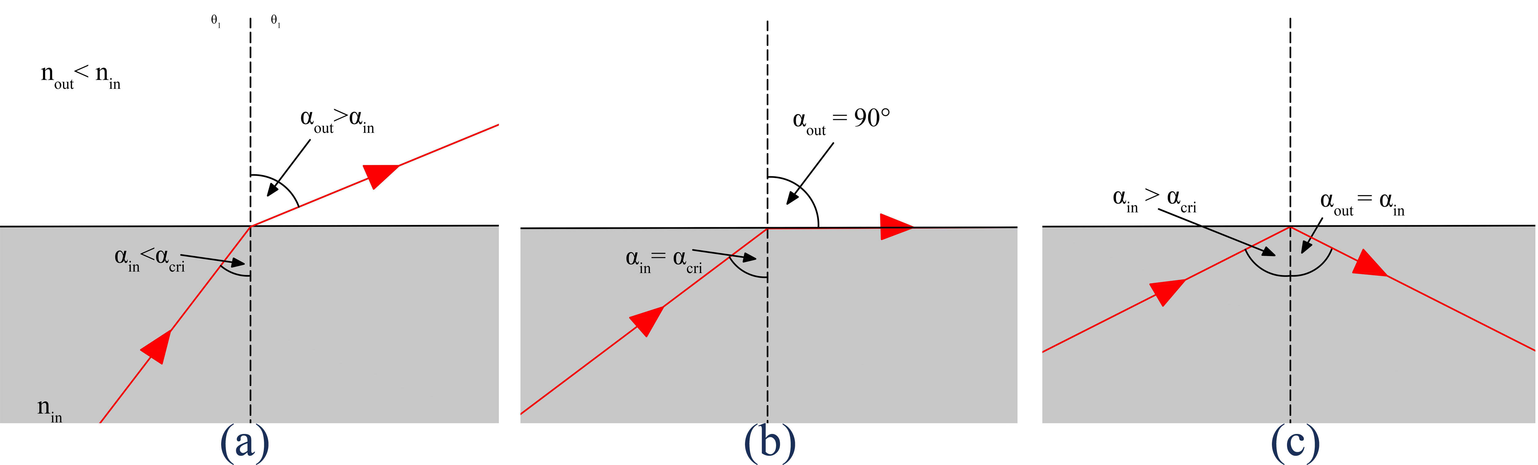
Fig. 1. Incidence angle and critical angle: (a) incidence angle less than the critical angle (b) incidence angle equal to the critical angle, and (c) incidence angle greater than the critical angle.
In order for the total internal reflection to take place, the light rays must travel from a denser medium (with higher refractive index (n1)) to a less dense medium (with lower refractive index (n2)), and the angle of incidence have to be greater than the critical angle in relation to the normal of the surface [20].
When the angle of refraction is at 90º the angle of incident is called the critical angle, this angle (acrit) for TIR can be found by using the Snell’s law of refraction (n1×sinain=n2×sinaout), and for the situation where a denser medium is surrounded by air (n2=1) and sin (aout = 90) = 1, the critical angle (acrit) is given by:
where acrit is the critical angle, 1 is the air density (temperature; pressure conditions), and n is the refractive index of the denser medium.
Knowing that the refractive index of acrylic glass is (1.9417), then its critical angle is:
acrit=Sin-1 (1/n1)
acrit =Sin-1 (1/1.49)
acrit = 42.15
Acrylic glass has a relatively a high refractive index to a small critical angle, so the light entering its medium will always have incident angle greater than the critical angle. This raise a suggestion that it is straight forward process and beneficial to design a device made from acrylic glass panel to harvest and trap the light rays until reaching the panel end part, and because of the high refractive index, a lot of incident light rays can be trapped by TIR.
2. Research Method
The applications of acrylic glass for light transmitting were investigated by using physical experimental models to evaluate acrylic glass panels at two stages. The first one to evaluate the daylight output at a diffuser point, and the second one was a real size daylighting chambers to evaluate the distribution of the transmitted light.
The illuminance levels were assessed under a clear sky, high solar radiation in semi- arid regions, Irbid, Jordan region. The experiment stages were conducted inside the campus of Jordan University of Science and Technology, Irbid at the north of Jordan, at the roof of department of Architecture and Building Design in a position that ensure a clear access to sunlight without any effect of shading from the surroundings.
In the first stage the illuminance levels of the transmitted light in the diffuser level were assessed in relation to the transmitting medium material, acrylic glass panel thickness, orientation, base material, and the heights of the collectors and the diffusers. The model was with the dimensions of (50*50*50) cm, as shown in Fig. 2 and the light sensor was installed on the model base. In the second stage the transmitted light distribution was tested by using two identical realistic size daylighting chambers that were built for the experiments with the dimensions of (200*200*200) cm, the lighting sensor was installed on a base with a height of 20 cm at a proportionally correct level below the different heights of the acrylic glass panels, as shown in Fig. 3.
Figure 2
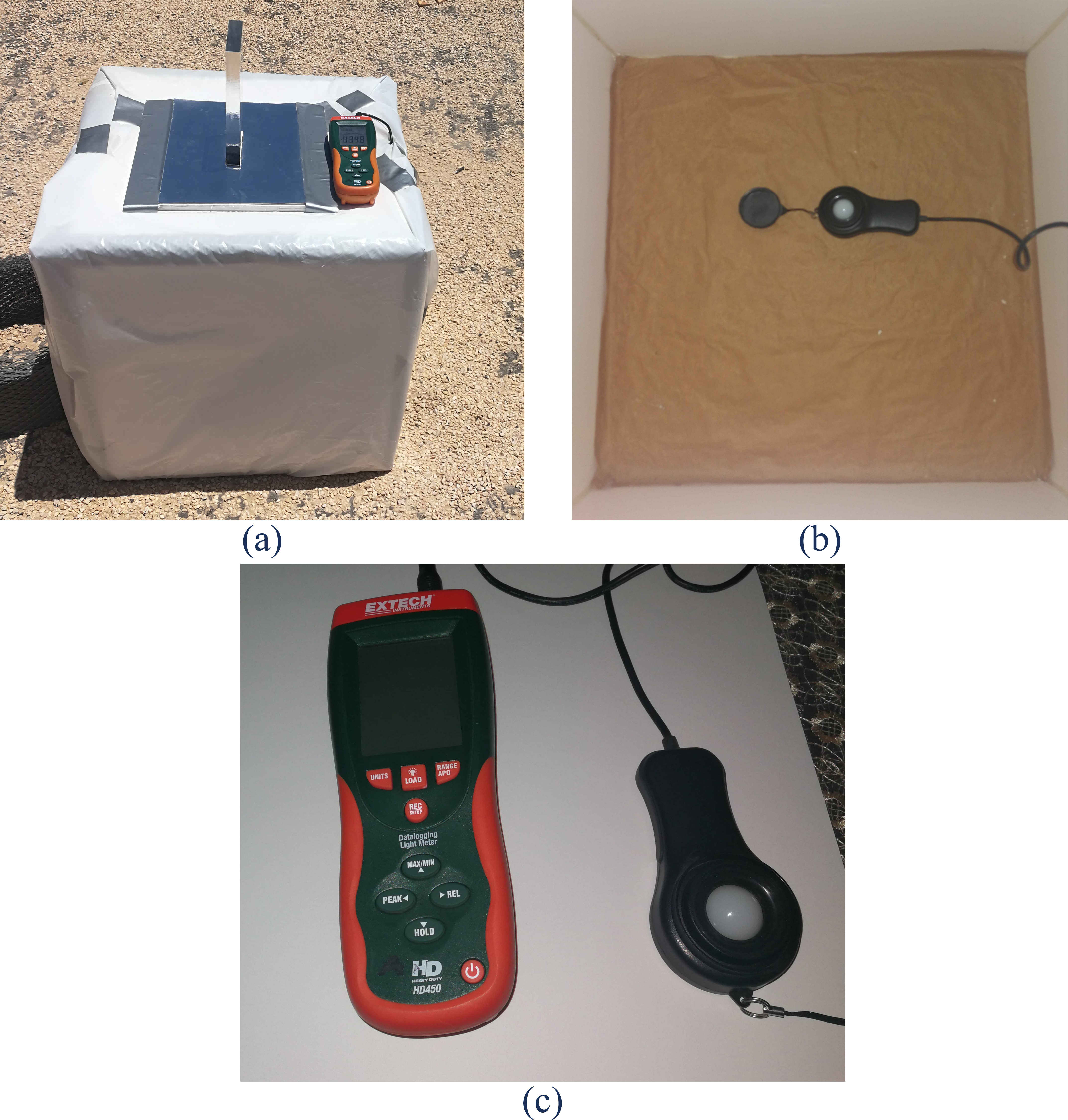
Fig. 2. (a)-(c) Stage one model and testing tool, EXTECH 450.
Figure 3
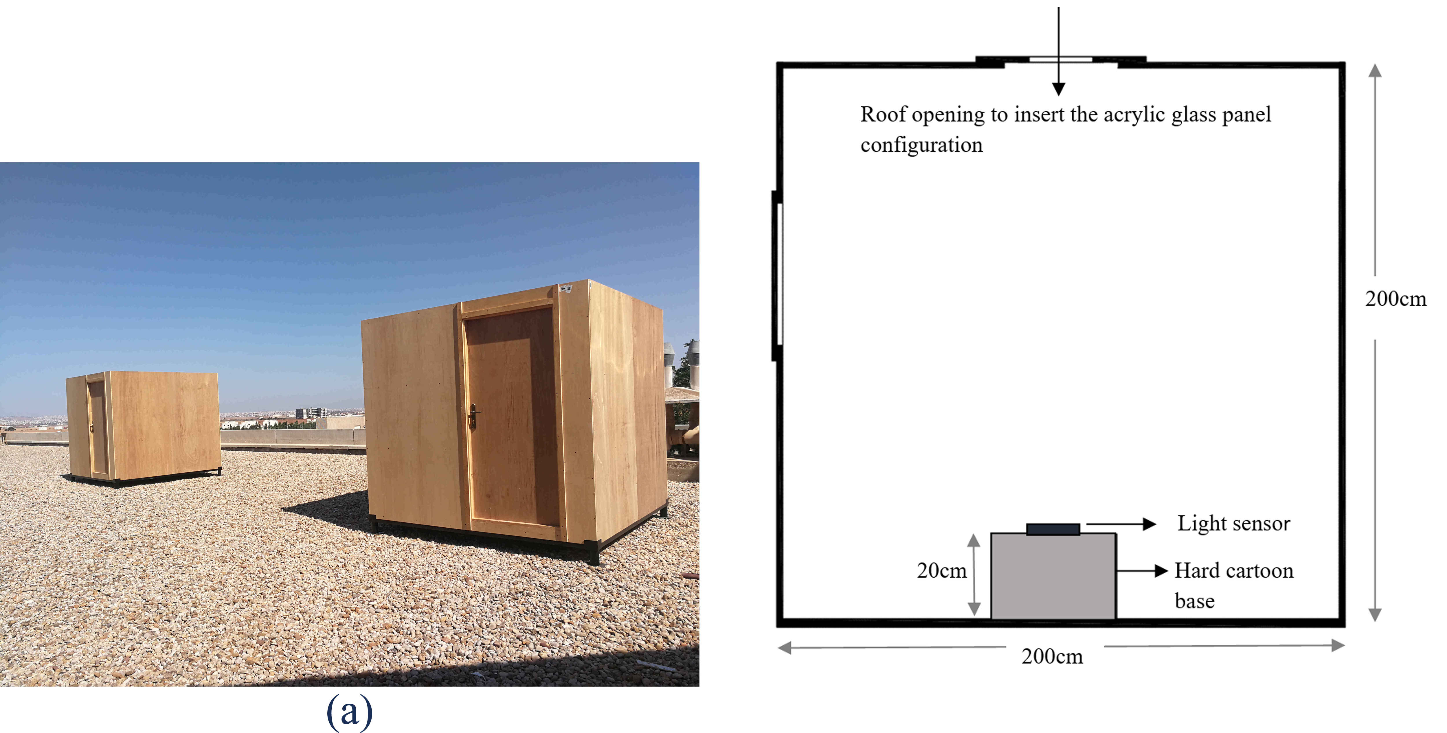
Fig. 3. (a) and (b) Stage two daylighting chambers.
The amount of light (in lux) amplified from the acrylic glass panel was measured by using a light meter data logger (EXTECH450 type). The results were translated into graphs and charts to ease the comparison between the variables, and readings were taken every 2 seconds to ensure the accuracy of the measurements; see Fig. 2.
3. Stage one
The main objectives of this stage were to test variables like comparing acrylic panel to an opening covered with glass with the same opening width, and studying the effect of the acrylic panel thickness, orientation, length and surrounding materials, and the heights of the collector and the diffuser on the overall transmitted light and the daylight performance at the diffuser end. In addition to design the main variables for the next stage. At this stage the six aforementioned variables were evaluated by using a reduced scale testing model in different months during the year, see Fig. 4.
Figure 4
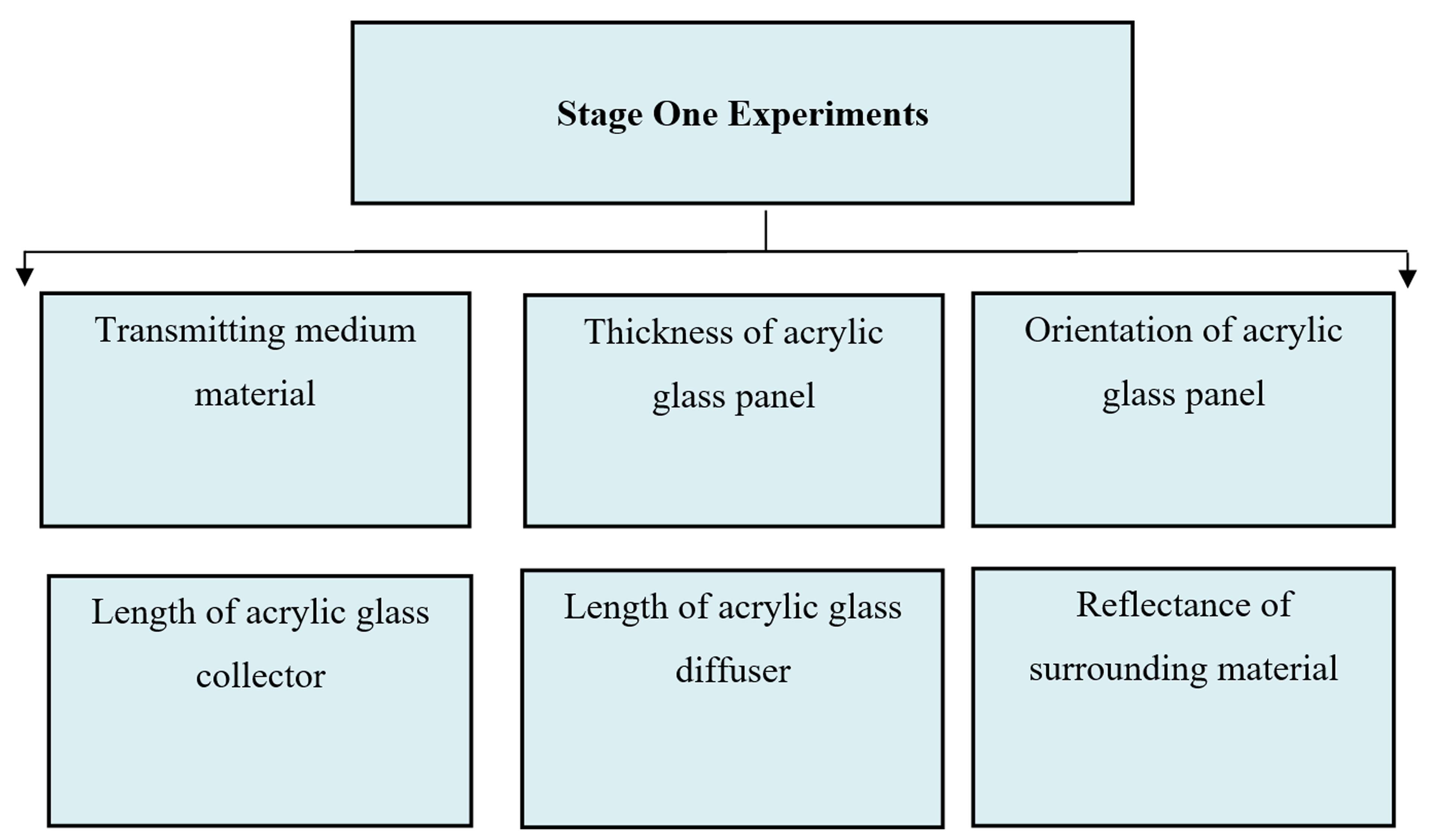
Fig. 4. Stage one experiments.
The basic results of the early stage are summarized as following:
This research found that acrylic glass panel could transmit light 7-8 times greater comparing to an opening covered with the glass with same opening width as shown in Table 1 and Fig. 5 below. The maximum illuminance level was (449.3 lux) for the acrylic glass panel in comparison with (55.1 lux) for the glass sheet.
Table 1
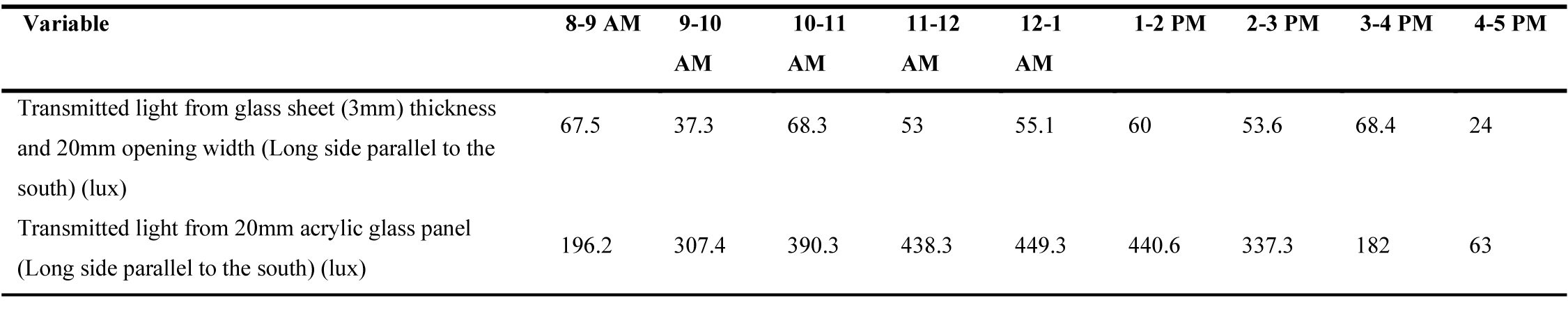
Table 1. Stage One/ Results of materials experiment as lighting transmitting mediums in February (winter time).
Figure 5

Fig. 5. Stage One/ Results of materials experiment as lighting transmitting mediums in February (winter time).
This research revealed that when increasing the thickness of acrylic glass panel, the illuminance levels increase, and when duplicating the thickness, the illuminance levels increase more than two times compared to the lower thicknesses during the peak hours as shown in Table 2 and Fig. 6. The angle of the incident light has a great impact on the amount of transferred light. The panel works efficiently with high angles rays striking on the normal of the section of the panel.
Table 2
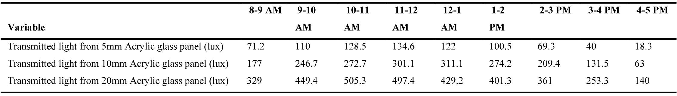
Table 2. Stage One/ Results of materials experiment as lighting transmitting mediums in February (winter time).
Figure 6

Fig. 6. Stage one/ acrylic glass panel thickness variables’ results in March (winter time).
This research showed that the orientation of the acrylic glass panel has a slight effect on the overall transmitted light, see Fig. 7. Increasing the length of collector part (external part) as shown in Fig. 8, or diffuser part (internal part) as shown in Fig. 9, slightly increase the illuminance level comparing to the effect of width or incident angles. The results for the surrounding materials showed that surrounding materials have less impact on the level daylight as shown in Fig. 10 comparing to panel thickness and the angle of the incident lights.
Figure 7

Fig. 7. Stage one/ acrylic glass panel orientation’ results in February (winter time).
Figure 8
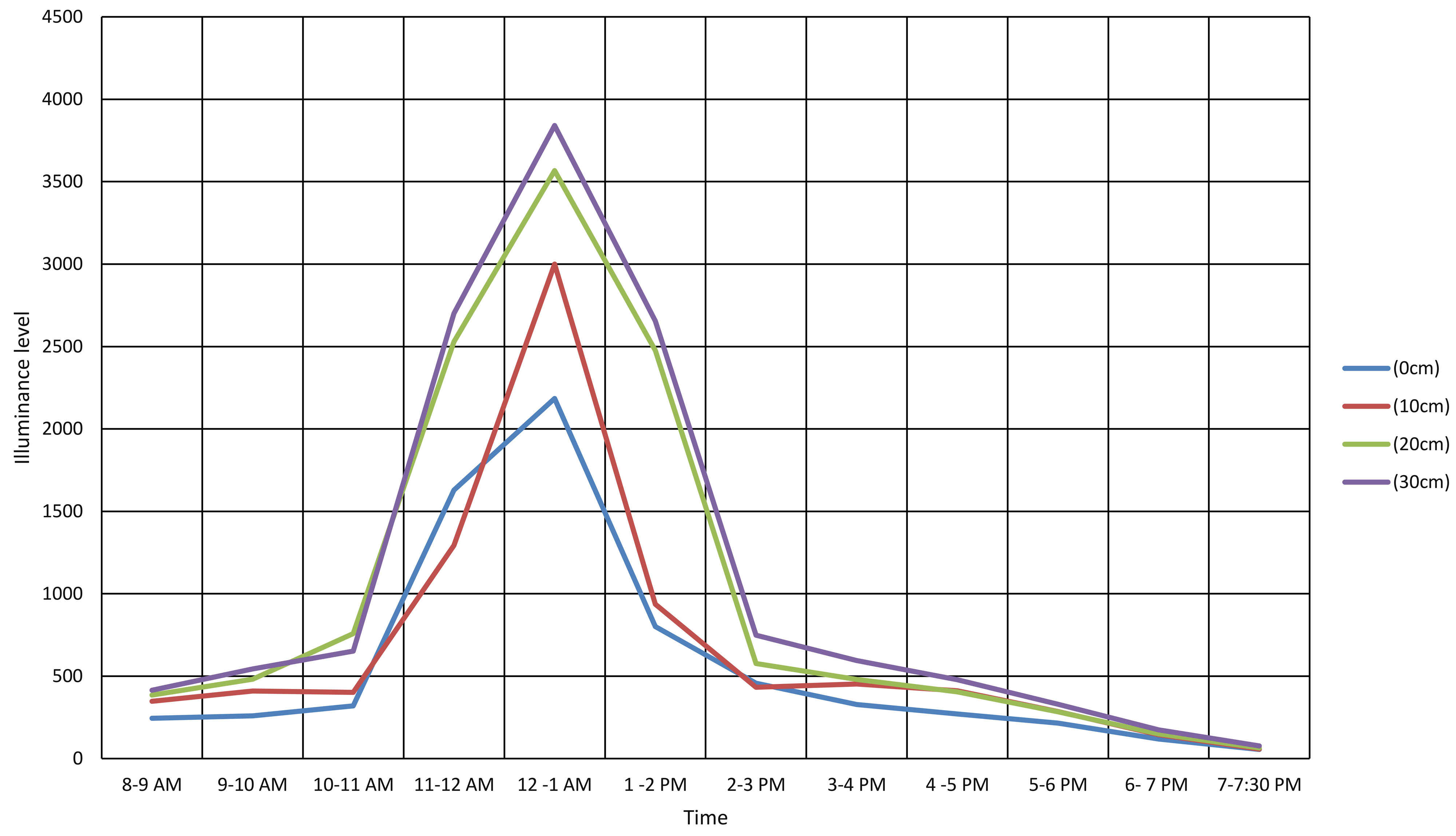
Fig. 8. Stage one/ length (cm) of acrylic glass panel collector results in July (summer time).
Figure 9
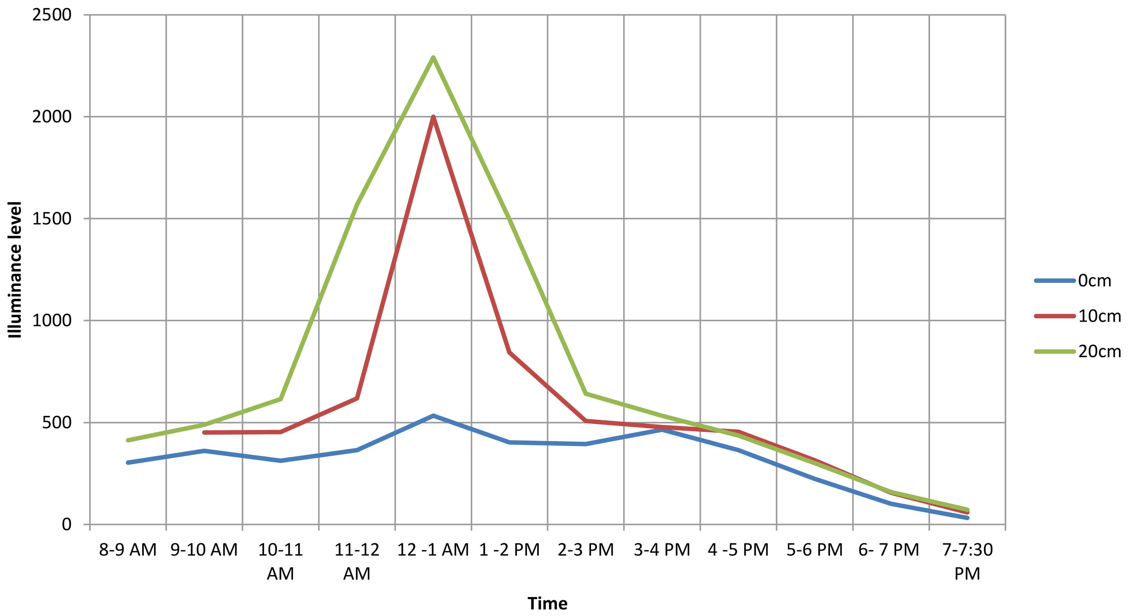
Fig. 9. Stage one/ length (cm) of acrylic glass panel diffuser in June (summer time).
Figure 10
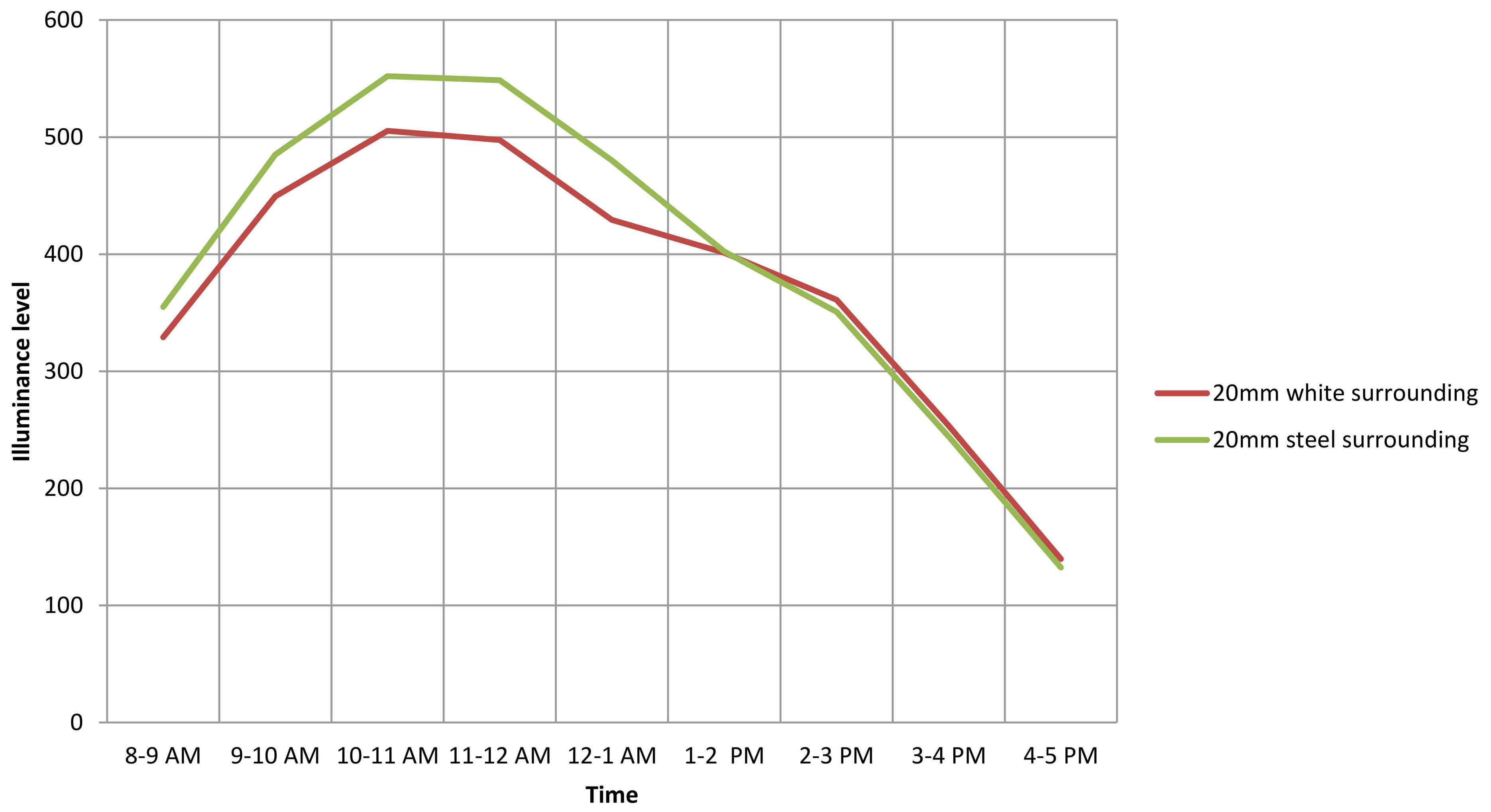
Fig. 10. Stage one/ results for the surrounding material experiment in March (winter time).
4. Stage two
The goal of this stage was to test the efficiency of acrylic glass panel to transmit light and the distribution of the transmitted light, see Fig. 11 that shows the the experiments of this satge.
Figure 11
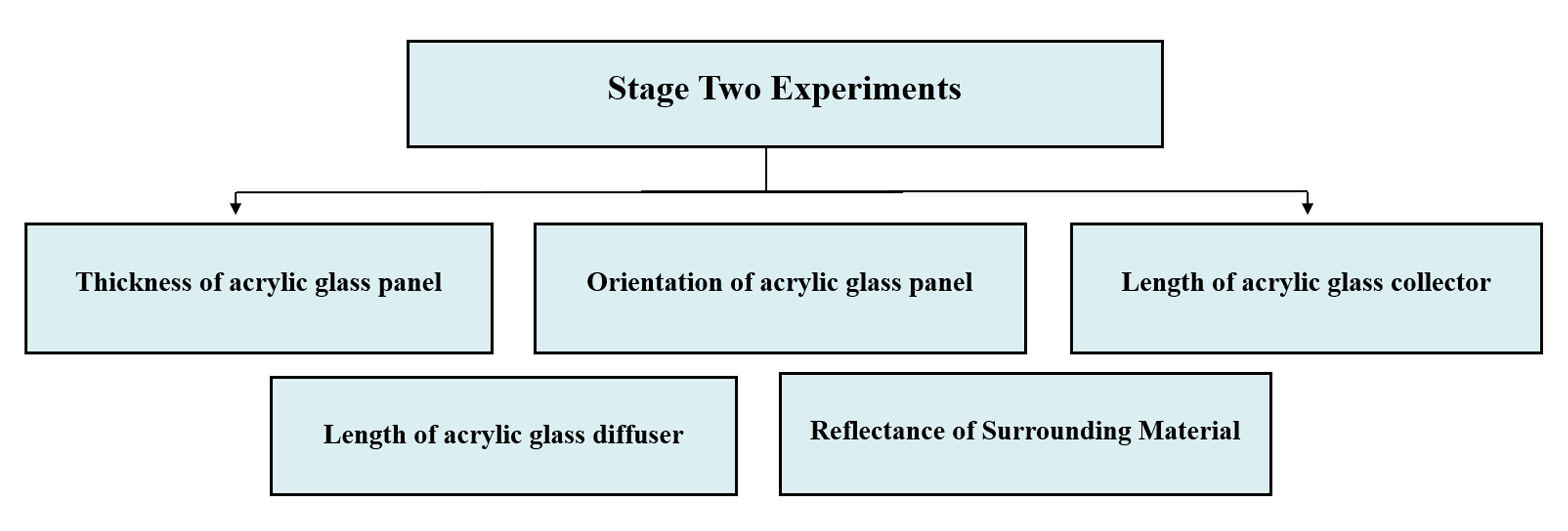
Fig. 11. Stage two experiments.
4.1. Acrylic glass panel thickness
This experiment investigated the effect of the acrylic panel thickness on the overall transmitted light; while the tested variables were (5 mm, 10 mm, and 20 mm considering that the fixed variables in this experiment were the (20 cm) collector, the (20 cm) diffuser, and the white surrounding. The experiments were done during full days to figure out the levels of the transmitted light for a different solar altitude angles, as shown in Fig. 12.
Figure 12
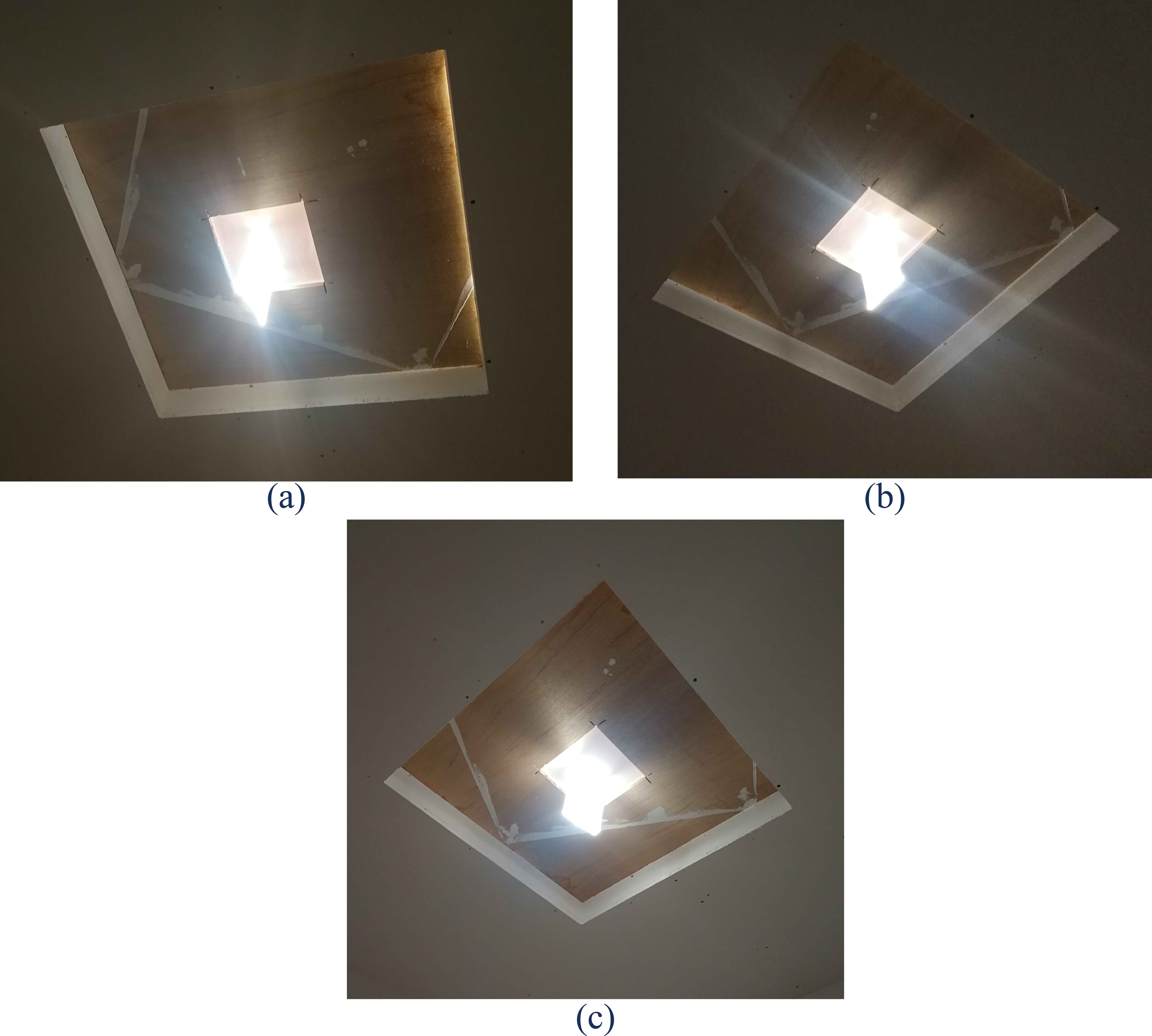
Fig. 12. Stage two/ Acrylic glass panel thickness configurations: (a) 5 mm, (b) 10 mm, and (c) 20 mm.
It was found that when increasing the thickness of acrylic glass panel, the illuminance levels increase, and the minimum thickness should be 20 mm for the applications of the acrylic glass panel on a real building while the number and distribution of the acrylic glass panels depend on the illuminance task levels needed, taking into consideration that the minimum illuminance level which is supplied by 20 mm thickness is 28.8 lux at early morning, as shown in Table 3 and Fig. 13.
Table 3

Table 3. Stage one/ Acrylic glass panel thickness variables’ results in March (winter time).
Figure 13
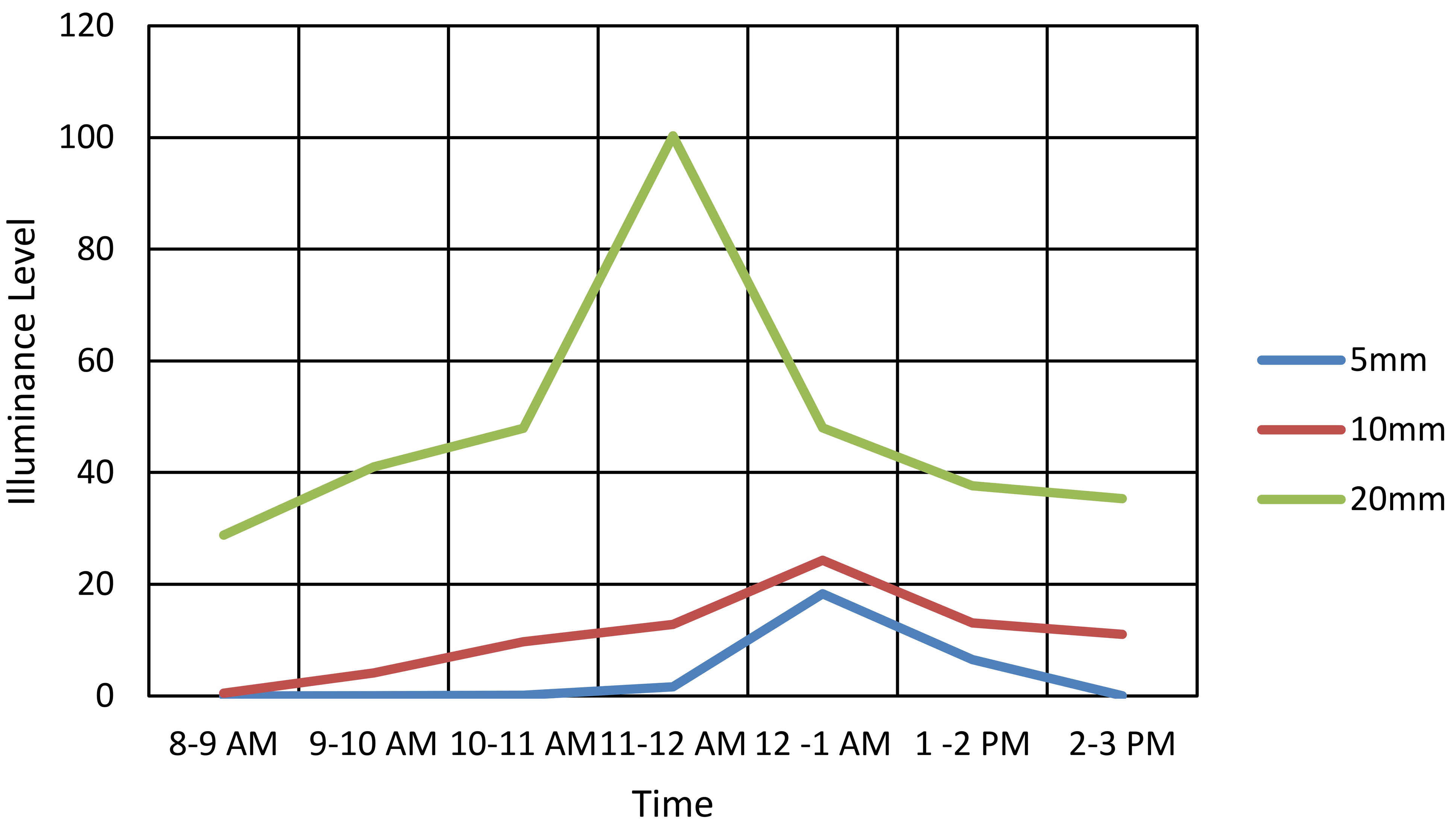
Fig. 13. Stage two/ thickness variables results in July (Summer time).
4.2. Width of acrylic glass collector
In this experiment the effect of increasing the width of acrylic glass panel collector on the overall transmitted light was tested and a comparison experiment between (15 cm and 20 cm) widths was done; these widths were determined according to what is available in the local market. The fixed variables were the 20 mm acrylic glass panel thickness, and 1m panel length (50cm collector length and 50 cm diffuser length), as shown in Fig. 14.
Figure 14
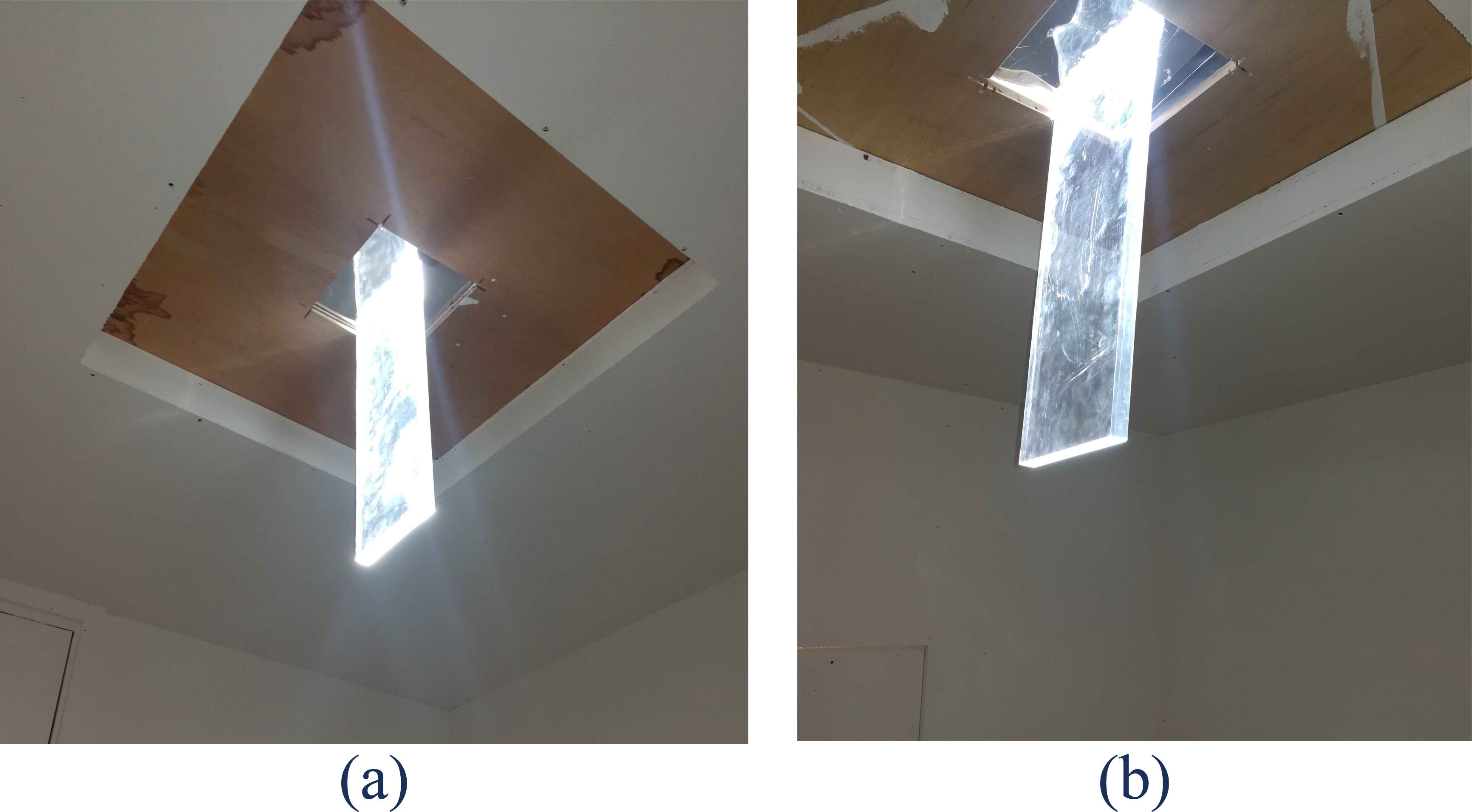
Fig. 14. Stage two/ collector width comparative experiment: (a) 15 cm and (b) 20 cm width.
This research indicated that when increasing the width of acrylic glass panel, the illuminance levels increases, while a 5 cm increase in width could increase the illuminance levels 1.5 times. The maximum illuminance level during November was (76 lux) during the peak hours for the 20 cm collector width, as shown in Table 4 and Fig. 15.
Table 4
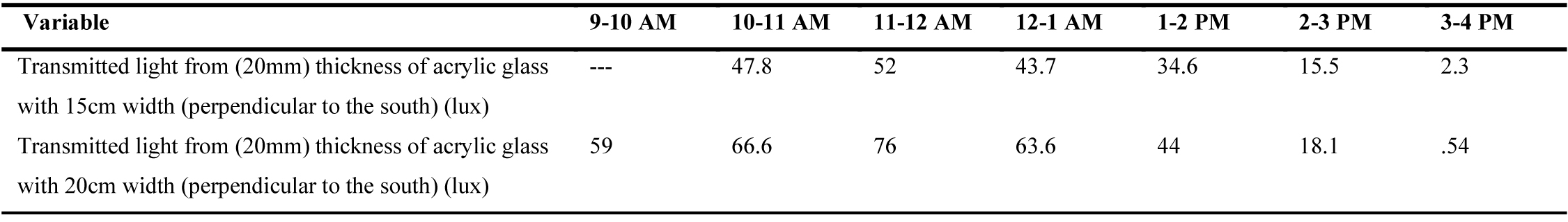
Table 4. Stage two/ results of acrylic glass collector width experiment in November (winter time).
Figure 15
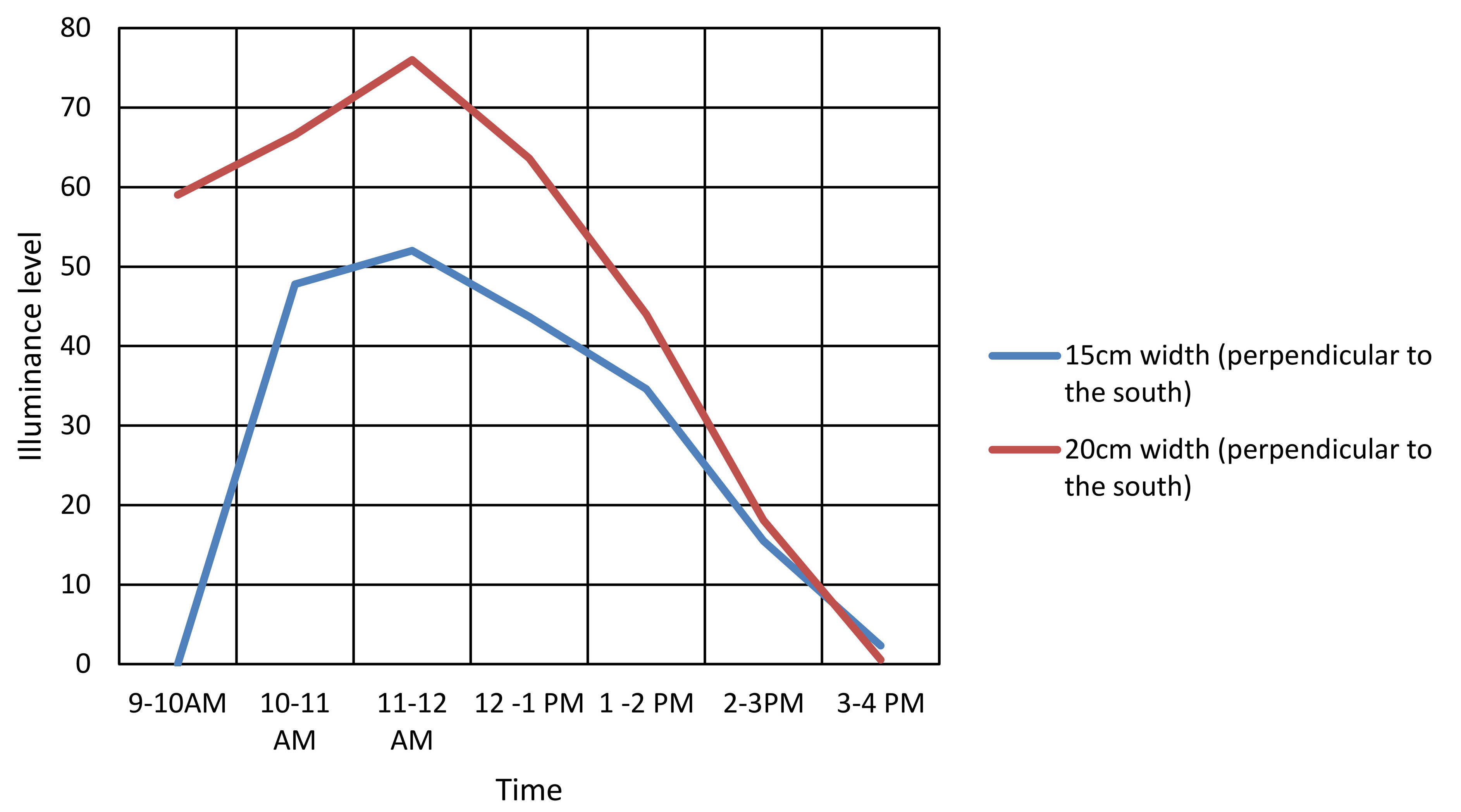
Fig. 15. Stage two/ results of acrylic glass collector width experiment (winter time).
4.3. Length (cm) of acrylic glass panel/ diffuser
This experiment investigated the effect of length of the acrylic glass panel diffuser on the overall transmitted light, where the long side of the acrylic glass panel was oriented perpendicular to the south, as shown in Fig. 16. Considering that the fixed variables in this experiment were the (20 mm) thickness, the (20 cm) collector. and (20 cm) panel width.
Figure 16
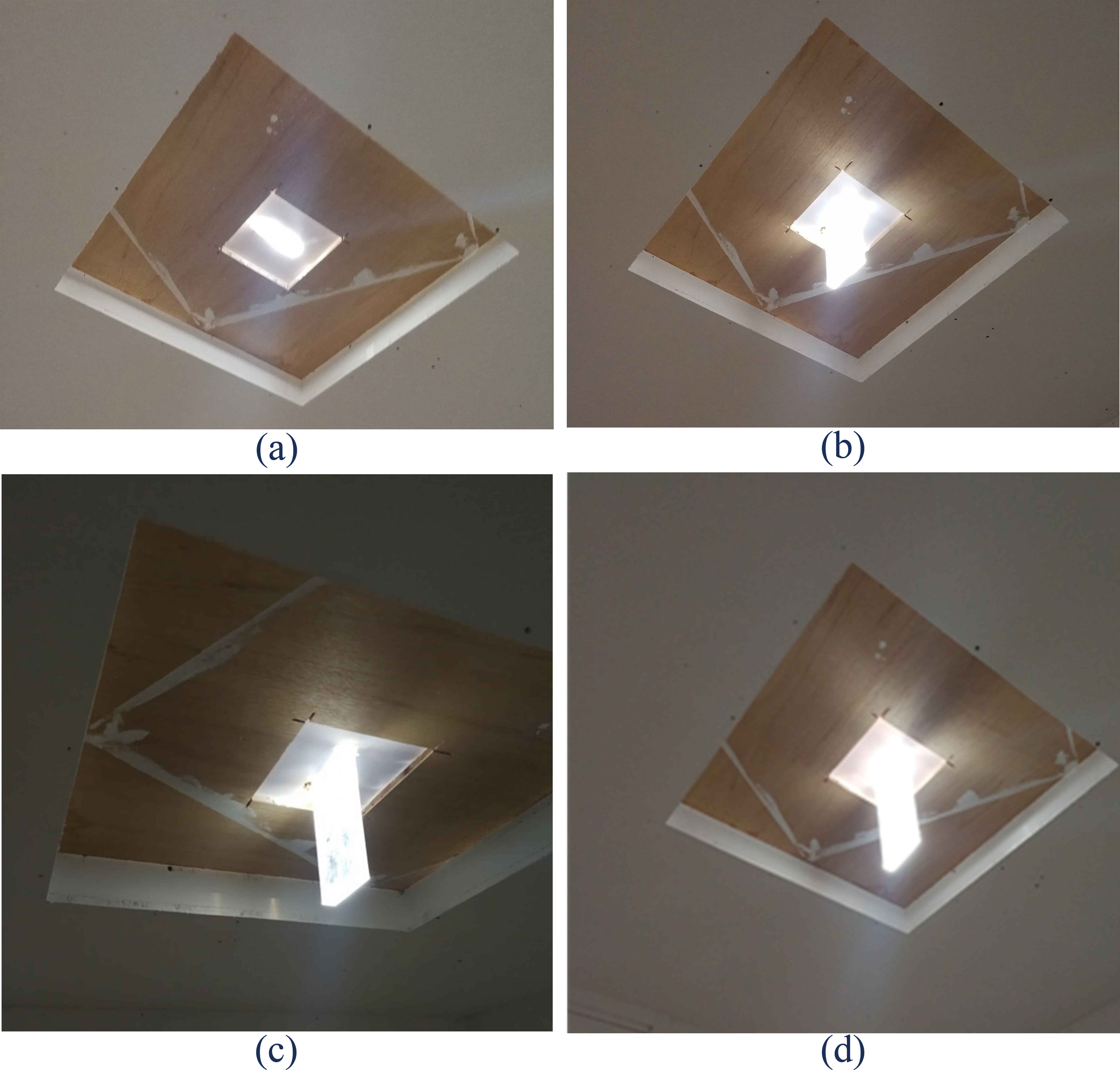
Fig. 16. Stage two/ length of acrylic glass panel/ diffuser experiment configurations: (a) 0 cm, (b) 10cm, (c) 20 cm, and (d) 30 cm.
This research showed that the illuminance level increases when the length of the diffuser increases, and the (30 cm) diffuser length showed the highest illuminance levels, and during the peak hours the illuminance levels for the (30 cm) diffuser length reach (495.5 lux) in July and around 3 times more than the (20 cm) diffuser length, as shown in Table 5 and Fig. 17.
Figure 17
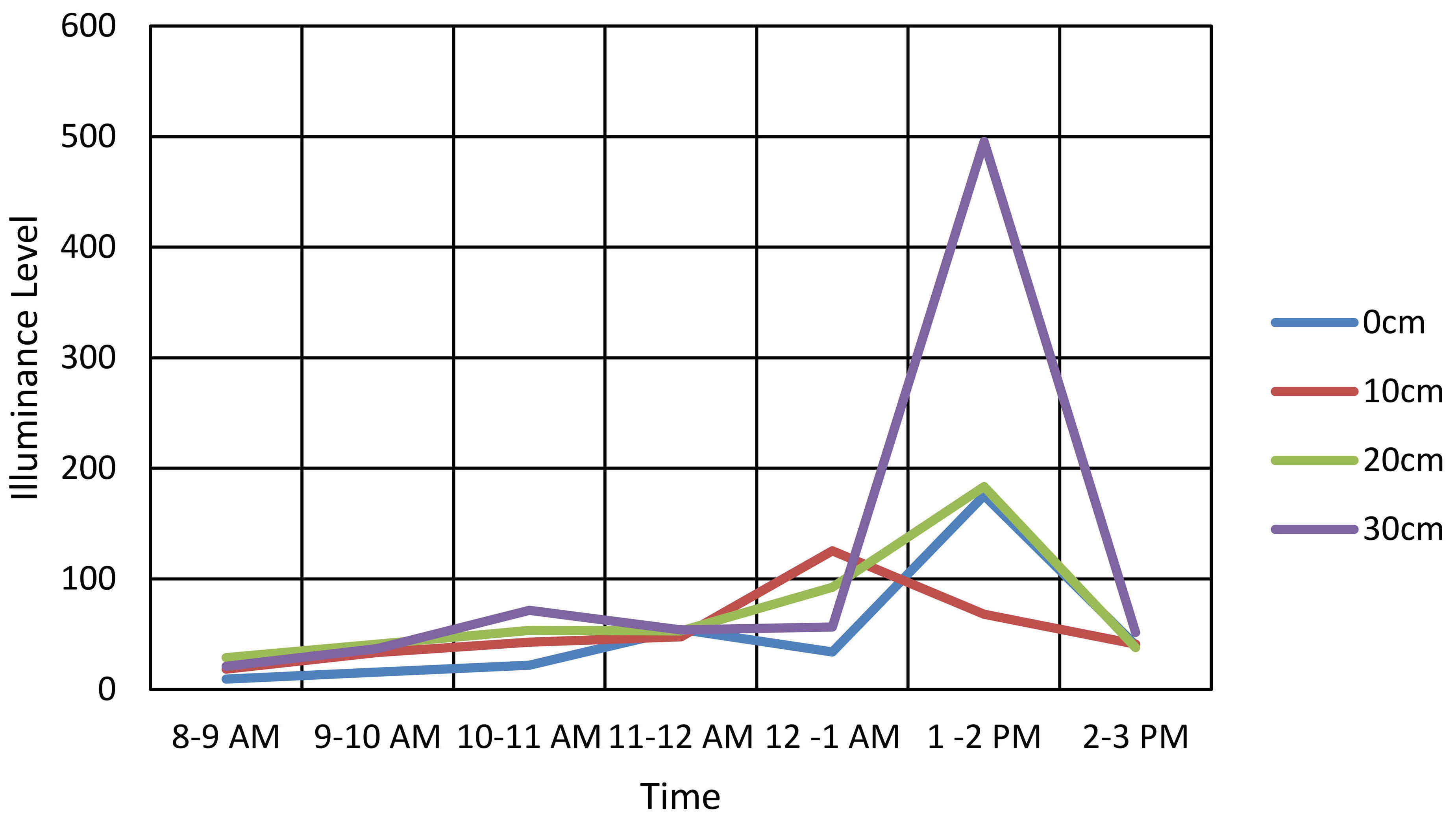
Fig. 17. Stage two/ results for length of acrylic glass panel/ diffuser experiment (summer time).
Table 5
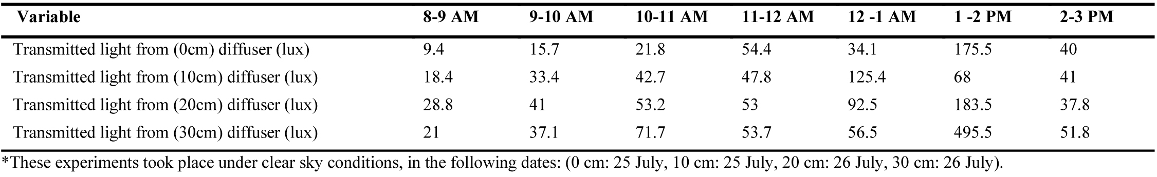
Table 5. Stage two/ results for length of acrylic glass panel/ diffuser experiment in July (summer time).
4.4. Length (cm) of acrylic glass panel collector
This experiment investigated the effect of the length of the acrylic glass panel collector on the overall transmitted light, where the long side of the acrylic glass panel was oriented perpendicular to the south.
It was found that the illuminance level increases when the length of the collector increases, and the (30 cm) collector length showed the highest illuminance levels, and during the peak hours the illuminance levels for the (30 cm) collector reach (586.7 lux) in July, and around 3 times more than the (20 cm) collector length, as shown in Table 6 and Fig. 18. Considering that the fixed variables in this experiment were the (20mm) panel thickness, the (20 cm) diffuser length, and (20 cm) panel width.
Table 6

Table 6. Stage two/ results for the height of acrylic glass panel collector experiment in July (summer time).
Figure 18
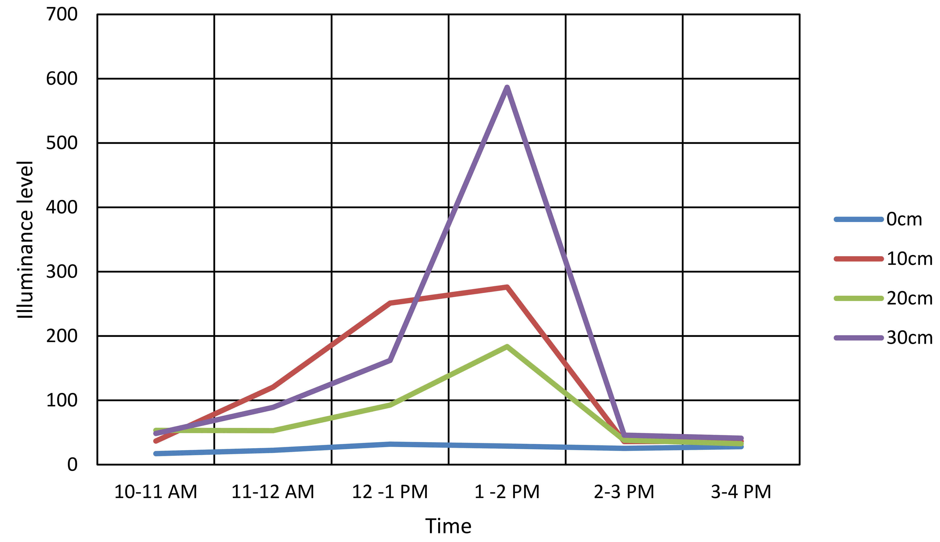
Fig. 18. Stage two/ results for the height of acrylic glass panel collector experiment (summer time).
4.5. Distribution of the transmitted light by acrylic glass panel
The lighting distribution was tested roughly in this experiment by checking the distribution of the transmitted light inside the daylighting champers, in which the two lighting sensors were used on both the centre and the corner of the daylighting chamber, as shown in Fig. 19.
Figure 19
Fig. 19. Stage two/ experiment for the transmitted light distribution.
This research revealed that the illuminance level distribution inside the room depends on the time of the day and the center location inside the room receives more consistence light levels, as shown in Table 7 and Fig. 20.
Figure 20
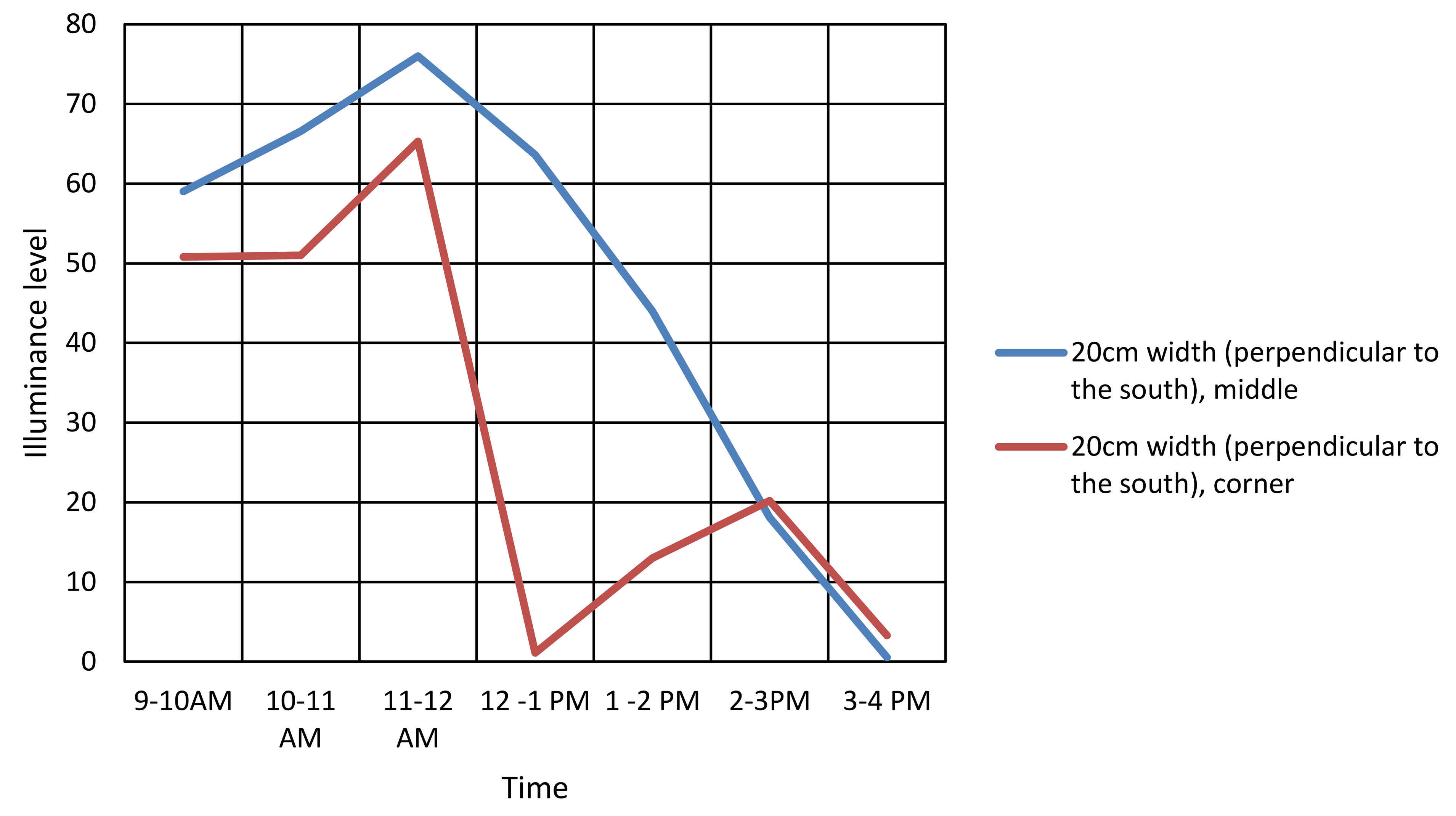
Fig. 20. Stage three/ results for the transmitted light distribution experiment.
Table 7

Table 7. Stage three/ results for the transmitted light distribution experiment in November (winter time).
It is recommended to have more than one acrylic glass panel distributed evenly within the room especially during the winter to have a more consistent lighting distribution, while the number of the panels will depend on the room area and the illuminance task level needed.
Snell's law was used to calculate the relationship between the angles of incidence and refraction, and the angles of leaving rays at the second end of the panel. It can be inferred from the experiments and explanation based on Snell' and Fresnel' equations and laws that high solar angles tend to refract more light with angles less than the incidence angles, critical angles, and less light transmitted light and so convey more light to the second of the panel. In on second hand low solar angles will refract part of the light with the critical angles and part of it will transmit from the panel sides. In addition increasing the length of the panel reduced the amount of light conveyed to the second due the increasing number of reflection and transmitted light. It is clear that increasing the length of the panel will work efficiently with large widths. And so using acrylic panel for long distance for basement required large widths.
In all cases the light strike the end of the acrylic panel is transferred efficiently through refraction and internal reflections compare to light strike the side of the panel, see Fig. 21.
Figure 21
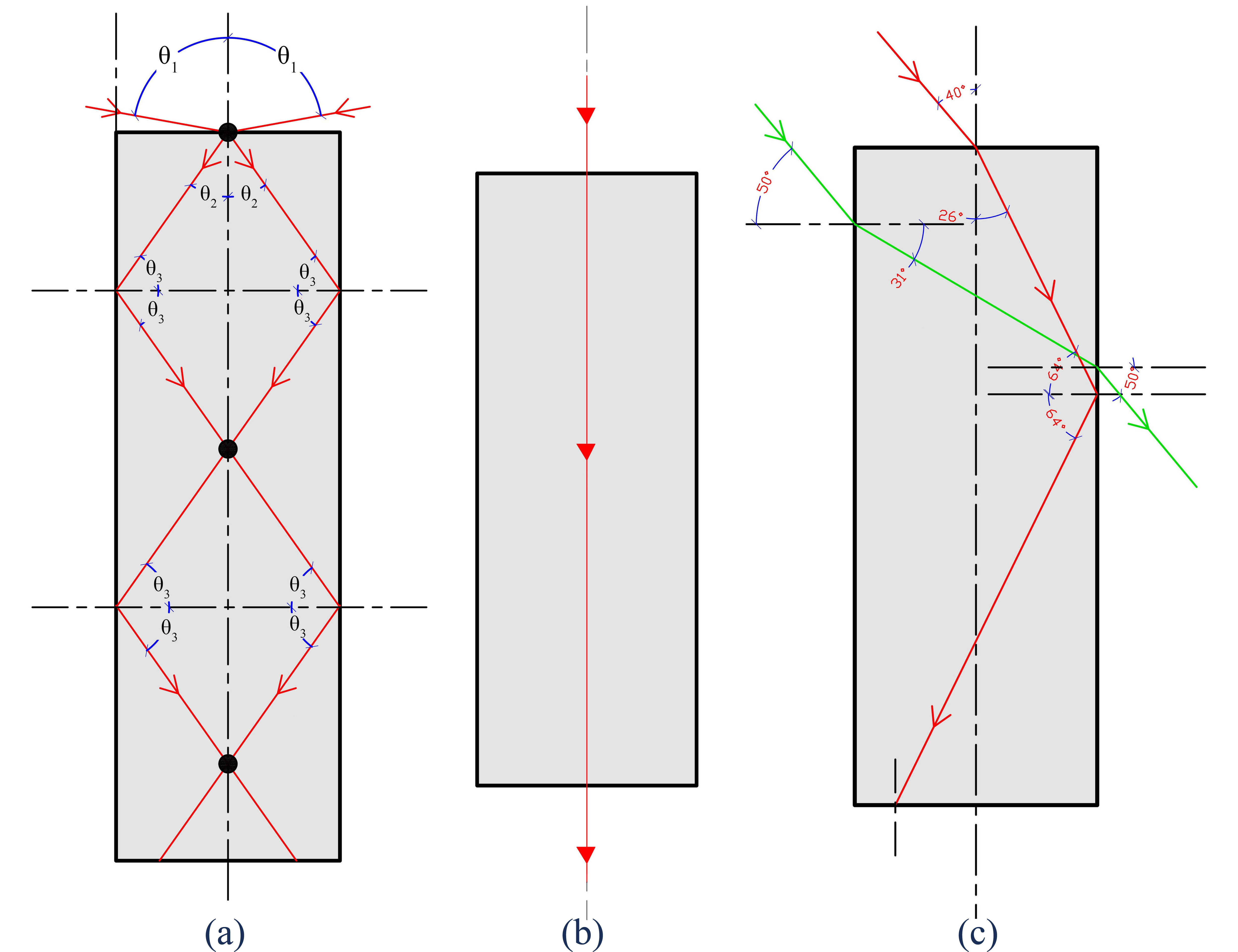
Fig. 21. Geometrical analysis for the light ray that enters the acrylic glass panel: (a) light rays intersect along the central axis, (b) angle 90º, and (c) angle 50º.
The results of the phase one shows many implications and considerations for using the acrylic panels as a daylighting device. Light behaviour within the panel showed that the most important part of the panel to collect and deliver the light to inner spaces is the external end of the panel and that the sides of the panel contribute less to the daylight performance. Accordingly, changing the surrounding materials will have less impact on the amount of light delivered through the panel. Increasing the area for the end surface of the panel helps in collecting and delivering more light to diffuser end when reach the area of it. At the same time the distributed area is better than a collected area means that using two panel with considerable width better than one panel with the double width, see Fig. 22.
Figure 22
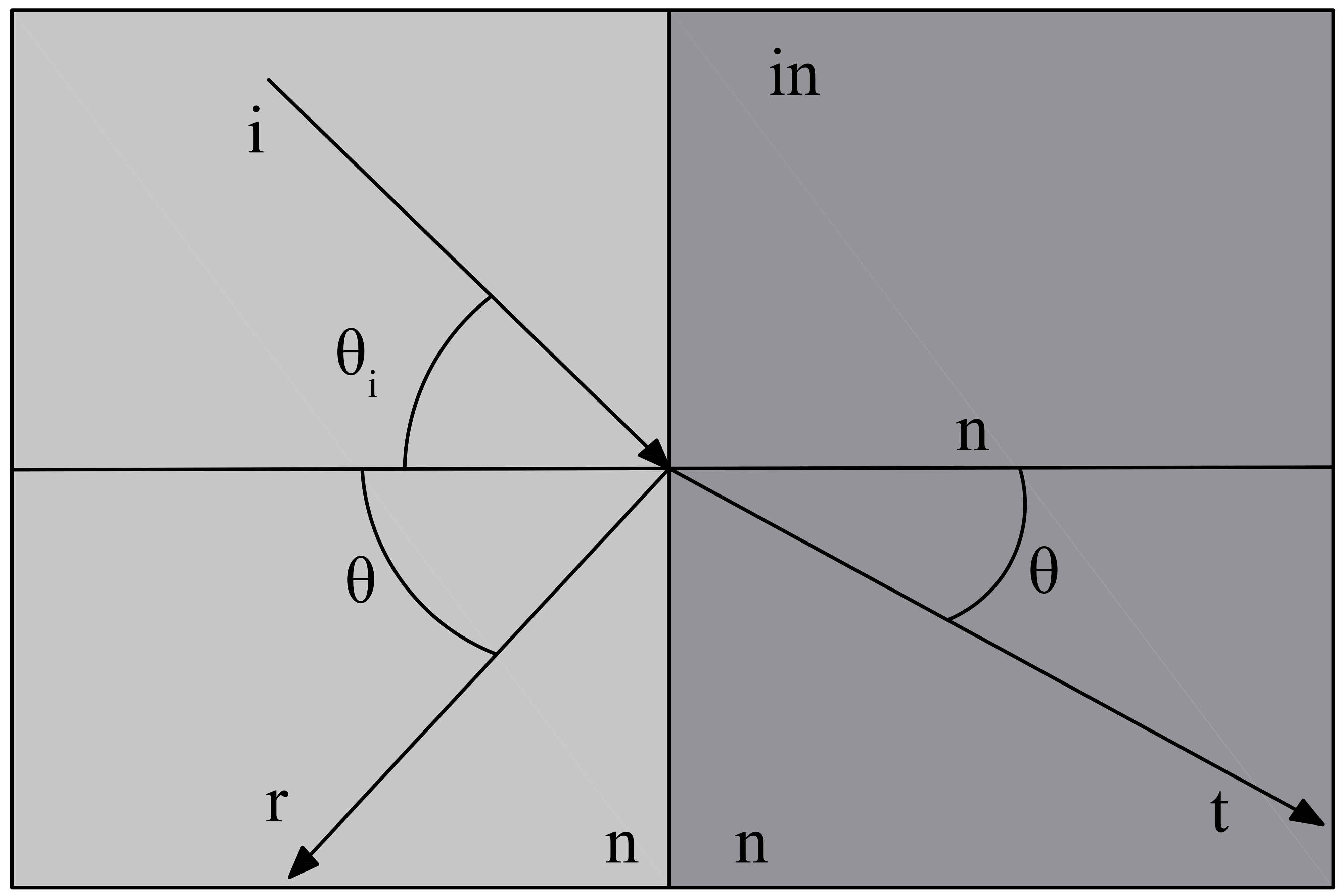
Fig. 22. Reflection and transmission coefficients of striking rays on different medium based on Fresnel equations.
5. Stage three
In this stage, the research explored the applications of acrylic panels as building construction material. Therefore three main properties indicators were investigated; physical properties, thermal properties and interactions with other materials like concrete.
Physical indicator includes the bearing capacity of the acrylic panels. The bearing capacity of acrylic panels showed high performance comparing to common building materials like concrete. Table 8 shows the main physical properties of acrylic panel which approve the possibilities of using the acrylic panels as building materials.
Table 8
![Physical Indicators of acrylic glass panel and concrete [22].](figures/7-258-31.jpg)
Table 8. Physical Indicators of acrylic glass panel and concrete [22].
Thermal indicators show high performance of acrylic panel as U value for heat transfer value as shown in Table 9.
Table 9
![Physical Indicators of acrylic glass panel and concrete [22].](figures/7-258-32.jpg)
Table 9. Physical Indicators of acrylic glass panel and concrete [22].
Many studies investigated the integration with other materials to be used as a building and construction materials. These studies showed good coherence and bond between acrylic materials and concrete, the potential of using acrylic bars as reinforcement of concrete comparing to steel, and many advantages of using acrylic bars like: high strength , stiffness, corrosion resistance, ease transportation and installation, and high load transfer at the interface concrete due to mechanical friction and mechanical interlock [23-28].
It could be concluded that acrylic panels is easily integrated with concrete and concrete mortar and so it could be used as construction materials.
Considering all of these advantages combined with light transferring abilities tested in the first phase, the acrylic panels will be an advance passive daylight device. Acrylic panel will have the features of conveying daylight without associated heat, conveying the daylight for long distances to windowless spaces, be part of building material, and be used as part of light design from the aesthetic point of view and Fig. 23 shows how these panels could be installed as part of wall design during the construction stages.
Figure 23
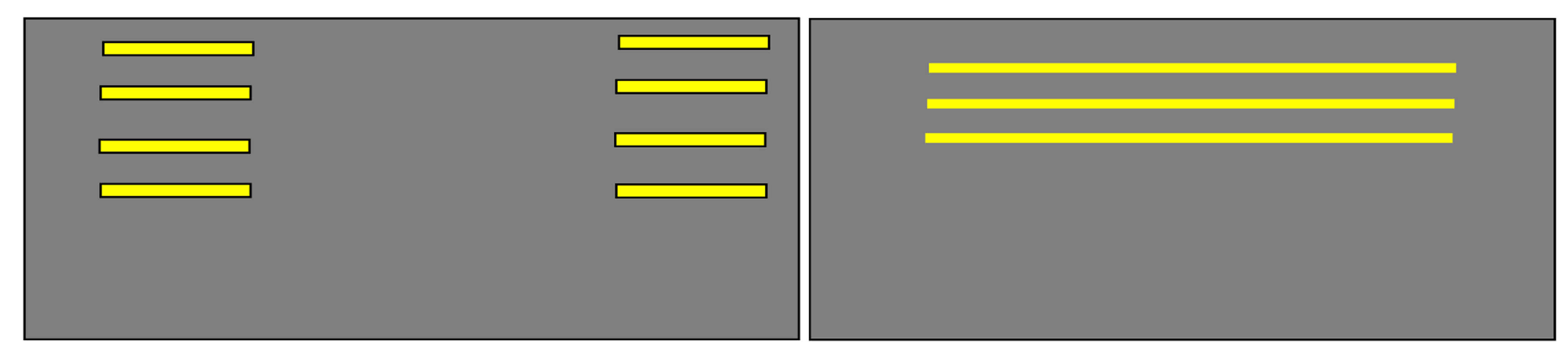
Fig. 23. Acrylic glass panels’ integration with building materials.
And so, the application of acrylic panel could be designed as part of walls and ceiling with direct contact to outside. In addition, it could be designed as daylight transfer devices for long distances for spaces without direct contact with outside. Moreover, the experiments showed that the acrylic panel could transfer low artificial or natural lighting from the collect end to the diffuse end. In this perspective the panel have the ability to convey the light from any source with minimum amount and direction.
6. Conclusion
Acrylic glass panels showed a great efficiency as lighting transporting medium (collector, transmitter, and diffuser) to the light for the spaces that don’t have direct contact with outside by utilizing the total internal reflection phenomena. Acrylic panels in addition to their potential of conveying light, they can reduce the glare and heat gain problems associated with direct daylighting systems, and minimize the effect on the space design layout that is associated with other light transporting techniques. Moreover, the acrylic glass panels could be easily integrated with building materials in walls and roofs.
This research found that acrylic glass panel showed a great potential for conveying light compared to conventional techniques, acrylic glass panel could transmit light 7-8 times greater than glass sheets, and there is a strong relation between the thickness, the width, the collector length, the diffuser length, and the reflectance of surrounding material of the acrylic panel on the overall transmitted light. When increasing the values of these variables, the illuminance levels of transmitted light increase, while the thickness of 20 mm, and the length of 30 cm collector, and 20cm diffuser, with a steel surrounding on both sides showed a great potential to transmit light up to 3493.3 lux during the peak hours in summer. While the test of the real size daylighting chamber showed that the acrylic glass could transmit light up to 580 lux during the peak hours in summer.
This research showed that there is a strong relation between the illuminance level of the transmitted light from acrylic glass panels and their thicknesses. When increasing the thickness of the acrylic glass panel, the illuminance levels increase, and when duplicating the thickness, the illuminance levels increase to more than two times compared to the lower thickness during the peak hours. It was found that the minimum thickness should be 20 mm for the applications for the acrylic glass panel on a real building while the number and the distribution of the acrylic glass panels depend on the illuminance task levels needed, while whatever the orientation of the acrylic glass panel, it has a slight effect on the overall transmitted light.
This research showed that when increasing the width of acrylic glass panel, the illuminance levels increases, while a 5 cm increase in width could increase the illuminance levels 1.5 times, and it is highly recommended to increase the width of the collector of acrylic glass panel in the locations of high solar angles, while it may not have a high effect on the locations of low solar angles as most of the light will enter in inclined angles from the panel sides and the length of the collector will have more effective effect.
Acrylic glass panels have great potentials for many applications like:
- Daylighting transmitting medium to underground floors, car parking.
- Daylighting transmitting medium to tunnels and subways that can be integrated within their structure.
- Efficient diffuser to artificial lighting
- Internal lighting decorations.
- Enhancing the performance of direct lighting techniques such as windows and skylights and work as light magnifier.
The initial cost of the acrylic glass panel is the main cost of this technique during the life time of the material, because the durability of PMMA material could reach up to 30 years which make this technique feasible to discuss and use, keeping in mind that the costs are predicted to reduce when the material is mass produced, while the maintenance cost will be lower in comparison with artificial lighting devices while considering the significant increase in the electricity cost during 30 years of the product life time.
Acknowledgement
Authors acknowledge the support of the current research by Jordan University of Science and Technology.
Contributions
R. AlQudah conducted the research and it’s experiments and prepared the manuscript draft. A. Freewan supervised the research and revised the manuscript.
Declaration of competing interest
The author declares that there is no conflict of interest.
References
- I.L. Wong, A review of daylighting design and implementation in buildings, Renewable and Sustainable Energy Reviews 74 (2017) 959-968. https://doi.org/10.1016/j.rser.2017.03.061
- N.A. Aldossary, Y. Rezgui, A. Kwan, Domestic energy consumption patterns in a hot and humid climate: A multiple-case study analysis, Applied Energy 114 (2014) 353-365. https://doi.org/10.1016/j.apenergy.2013.09.061
- W.S.E. Ismaeel, Drawing the operating mechanisms of green building rating systemsm, Journal of Cleaner Production 213 (2019) 599-609. https://doi.org/10.1016/j.jclepro.2018.12.115
- R.W. Amstalden, M. Kost, C. Nathani, D.M. Imboden, Economic potential of energy-efficient retrofitting in the Swiss residential building sector: The effects of policy instruments and energy price expectations, Energy Policy 35 (2007) 1819-1829. https://doi.org/10.1016/j.enpol.2006.05.018
- F. Asdrubali, I. Ballarini, V. Corrado, L. Evangelisti, G. Grazieschi, C. Guattari, Energy and environmental payback times for an NZEB retrofit, Building and Environment 147 (2019) 461-472. https://doi.org/10.1016/j.buildenv.2018.10.047
- I. Wong, H.X. Yang, Introducing natural lighting into the enclosed lift lobbies of highrise buildings by remote source lighting system, Applied Energy 90 (2012) 225-232. https://doi.org/10.1016/j.apenergy.2011.03.018
- T. Hong, M.A. Piette, Y. Chen, S.H. Lee, S.C. Taylor-Lange, R. Zhang, K. Sun, P. Price, Commercial Building Energy Saver: An energy retrofit analysis toolkit. Applied Energy 159 (2015) 298-309. https://doi.org/10.1016/j.apenergy.2015.09.002
- A.A. Freewan, L. Shao, S. Riffat, Optimizing performance of the lightshelf by modifying ceiling geometry in highly luminous climates. Solar Energy 82 (2008) 343-353. https://doi.org/10.1016/j.solener.2007.08.003
- A.A.Y. Freewan, J.A. Al Dalala, Assessment of daylight performance of Advanced Daylighting Strategies in Large University Classrooms; Case Study Classrooms at JUST, Alexandria Engineering Journal 59 (2020) 791-802. https://doi.org/10.1016/j.aej.2019.12.049
- L. Yang, X. Liu, F. Qian, S. Du, Ventilation effect on different position of classrooms in “line” type teaching building, Journal of Cleaner Production 209 (2019) 886-902. https://doi.org/10.1016/j.jclepro.2018.10.228
- Z. Wu, N. Li, P. Wargocki, J. Peng, J. Li, H. Cui, Adaptive thermal comfort in naturally ventilated dormitory buildings in Changsha, China, Energy and Buildings (2019). https://doi.org/10.1016/j.enbuild.2019.01.029
- J. Song, Y. Zhu, Z. Jin, Y. Yang, Daylighting system via fibers based on two-stage sun-tracking model, Solar Energy 108 (2014) 331-339. https://doi.org/10.1016/j.solener.2014.07.021
- F.a. Chi, R. Wang, G. Li, L. Xu, Y. Wang, C. Peng, Integration of sun-tracking shading panels into window system towards maximum energy saving and non-glare daylighting, Applied Energy 260 (2020) 114304. https://doi.org/10.1016/j.apenergy.2019.114304
- M.S. Mayhoub, Innovative daylighting systems’ challenges: A critical study, Energy and Buildings 80 (2014) 394-405. https://doi.org/10.1016/j.enbuild.2014.04.019
- M. Mayhoub, hybrid lighting systems; application and evaluation, Doctor in philosophy thesis in University of Liverpool, Liverpool, 2011.
- S.M. Hosseini, M. Mohammadi, T. Schröder, O. Guerra-Santin, Integrating interactive kinetic façade design with colored glass to improve daylight performance based on occupants’ position, Journal of Building Engineering 31 (2020) 101404. https://doi.org/10.1016/j.jobe.2020.101404
- A.A.Y. Freewan, A.A. Gharaibeh, M.M. Jamhawi, Improving daylight performance of light wells in residential buildings: Nourishing compact sustainable urban form, Sustainable Cities and Society (2014). https://doi.org/10.1016/j.scs.2014.04.001
- IEA-Task-21, Daylighting in Buildings, in, http://www.iea-shc.org/task21/, 1999.
- A.A. Freewan, Developing daylight devices matrix with special integration with building design process, Sustainable Cities and Society 15 (2015) 144-152. https://doi.org/10.1016/j.scs.2014.11.003
- J.M. Callow, L. Shao, Air-clad optical rod daylighting system, Lighting Research and Technology 35 (2003) 31-38. https://doi.org/10.1191/1477153503li081oa
- J. Callow, Daylighting Using Tubular Light Guide Systems, in, University of Nittingham, 2003.
- METWEB, http://www.matweb.com/search/datasheet.aspx?bassnum=O1303&ckck=1, in, Blacksburg, 2020.
- M.X. Suong V. Hoa, Interface between Fiber Reinforced Plastic Rod and Concrete in: 13th international conference on composite materials, Beijing, 2013.
- S.M. Raoof, L.N. Koutas, D.A. Bournas, Bond between textile-reinforced mortar (TRM) and concrete substrates: Experimental investigation, Composites Part B: Engineering 98 (2016) 350-361. https://doi.org/10.1016/j.compositesb.2016.05.041
- M.A. C. Gonilho-Pereira & S. Jalalim R. Fangueiro, P. Pina Marques, Hybrid composite rods for concrete reinforcement, Structures and Architecture, 5 (2010).
- C.J. R. Ram Manohar, Behavior of Non Metallic Reinforcement (FRP) In Beam, International Journal for Trends in Engineering & Technology, 6 (2015) 55-59.
- Farzad H. Shahnaz Basim, Raizal Saifulnaz Bin Muhammad Rashid, Embedded carbon fiber‑reinforced polymer rod in reinforced concrete frame and ultra‑high‑performance concrete frame joints, International Journal of Advanced Structural Engineering 11 (2019). https://doi.org/10.1177/1477153509104013
- R.F. C. Gonilho Pereira, S. Jalali, M. Araújo, P. Marques, Composite Rods as a Steel Substitute in Concrete Reinforcement in: Conference of Sociedade Portuguesa De Materiais (Materiais 2007), Faculdade de Engenharia da Universidade do Porto, 2007.
Copyright © 2020 The Author(s). Published by solarlits.com.

SHARE ON


