Article Outline
Figures and tables
Volume 6 Issue 1 > pp. 1-10 • doi: 10.15627/jd.2019.1
Towards New Design of Laser Cut Acrylic Panels for Windows
Andreas Weibye, Barbara Matusiak*
Author affiliations
Department of Architecture and Technology, Norwegian University of Science and Technology (NTNU), Trondheim, Norway
* Corresponding author.
andreas.weibye@gmail.com (A. Weibye)
barbara.matusiak@ntnu.no (B. Matusiak)
History: Received 12 October 2019 | Revised 4 January 2019 | Accepted 9 January 2019 | Published online 15 January 2019
Copyright: © 2019 The Author(s). Published by solarlits.com. This is an open access article under the CC BY license (http://creativecommons.org/licenses/by/4.0/).
Citation: Andreas Weibye and Barbara Matusiak, Towards New Design of Laser Cut Acrylic Panels for Windows, Journal of Daylighting 6 (2019) 1-10 http://dx.doi.org/10.15627/jd.2019.1
Figures and tables
Abstract
This paper builds upon existing research into laser cut panels and aims to find new design-patterns that would improve daylighting conditions of existing rooms when applying the laser-cut panels on vertical windows. The primary area of exploration is looking for new design patterns and their ability to both deflect and spread the incoming light into the simulated room. Repeating wave patterns and a parametric pattern of laser cuts in a transparent acrylic sheet were studied in a scale model. The original linear design invented by Ian Edmond was also included. The study was carried out using artificial sun at the Daylighting laboratory at NTNU. The results indicate that deflecting of light is closely related to the panels’ D/W-ratio (distance between cuts/width of the panel) and the panels’ ability to spread light is related to the magnitude of curvature in the pattern-design. The parametric pattern and the wave pattern have both shown very promising results and are recommended for application in real buildings. The paper also describes a new research method based on the analysis of false colour images developed from HDR images, created from a series of photos taken with a fish-eye camera in a scale model.
Keywords
Daylighting; Laser cut panels; Light distribution; Windows
1. Introduction
Several studies have shown that transparent acrylic plates cut with laser [1,2] can be an effective and useful device, which can significantly improve the daylighting conditions of existing rooms [3,4]. Laser Cut Panels (LCPs) are usually designed to cover the upper part of the window i.e. over the eye height. This enables users of the room to enjoy an unobstructed view to the outside while still benefiting from the LCPs ability to deflect incoming daylight deeper into the room and create better daylighting conditions. The same studies also point out some concerns about glare as the Edmonds panels deflect light into the room in a rather focused beam, creating hot-spots of high luminance.
Edmonds’ original design shows a clear correlation between the design of the linear pattern cut into the acrylic and the panels’ ability to deflect incoming light at a specific angle of incidence [1]. Using the linear pattern design, the panels can be optimized for a particular angle of incidence in which near 100% of incoming light is deflected, but the range in which these panels can effectively deflect light is narrow and decreases as the “angle of optimal incidence” decreases. Furthermore, the Edmond panels have been tested in real buildings in overcast sky conditions [5,6], with no significant change in the light level or distribution in the room compared to clear glass.
In the urban context, e.g. a street, where the light from the sky is approaching from a narrow angle such that the diffuse light has a dominant direction, the optimally sloped LCPs effectively reflect the light to the interiors at lower floors [7].
In previous studies, Matusiak experimented with LCPs to improve daylighting conditions in students’ studios using LCPs mounted horizontally beneath skylights [8]. The pattern of cuts was developed to 1) maximize the deflection of sun rays around the skylight by optimizing the form, size and position of cuts and to 2) allow as large as possible penetration of the diffuse light from the sky by maximizing perforation degree of the panel. This resulted with a pattern consisting of regularly repeating circles. As a result, the stationary LCPs disperse light around skylights regardless of sun azimuth angle and simultaneously the vertical light from the overcast sky has nearly unobstructed way down to the room, a solution which proved highly successful regarding the light level and the appreciation by the users.
A similar idea was also tested onto a vertically mounted LCPs in the following research project [9] where a repetitive pattern of half circular cuts was examined. It was proved that the use of curves in the pattern design can increase spreading of the deflected light to the sides and reduce solar glare but the luminance contrast may be high.
This paper aims to study various pattern designs in a vertical acrylic panel mounted on or nearby the window glass to increase side-spreading of light into the room.
2. Laser cut panel
The LCP was invented in 1989 by Ian Edmonds and consists of a thin transparent acrylic sheet in which a laser-cutter make linear cuts perpendicular to the surface. These cuts create internal reflective surfaces that, combined with refraction of light through the acrylic medium, can deflect light. Edmonds’ primary design parameters were line-spacing D to panel depth/width W, as seen in Fig. 1. Edmonds found that the D/W-ratio was the primary defining factor for the panels’ performance at a given angle of incidence and calculated that there would be one angle of incidence for each D/W ratio in which near to all light would be deflected, ignoring luminance loss throughout the system [1].
Figure 1
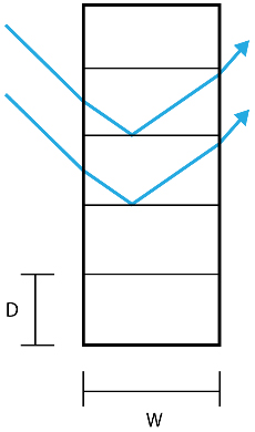
Fig. 1. Light refraction and deflection through the LCP.
Low D/W ratios give better performance at lower angles of incidence when mounted on a vertical surface but have a very narrow range of effective operation. Increasing the D/W ratio increases both the angle of “optimal incidence” and the range of useful operation but at the cost of losing the ability to deflect light at lower angles of incidence (Fig. 2) [1].
Figure 2
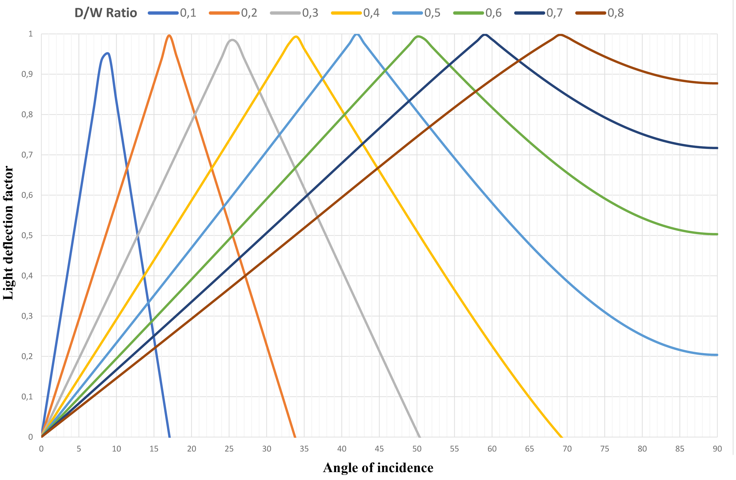
Fig. 2. Light deflection of increasing D/W ratios for Edmonds original panel design.
3. Procedures and methodology
3.1. Material selection
Three primary attributes were considered when selecting the type of acrylic to manufacture the panels. Most importantly, we needed an acrylic material which the laser-cutter at our university (see 3.2) would be able to cut through, followed by the requirement of having acrylic of high optical quality and lastly using a material thickness that would produce cuts of highest possible optical qualities. Through experimentation of materials and fine-tuning of the laser-cutter, PLEXIGLAS PMMA 0F00 was chosen from manufacturer and distributor VINK Norway AS. This material has a refraction index of 1.491, and panels with 6 mm thickness were found to give the best results in the laser-cutter. The acrylic sheets were cut into panels of 150×150 mm and mounted on a cutting-bed with the patterns cut into them.
3.2. Panel design
Designing patterns that can both deflect and spread light, the horizontal line design of the Edmonds panel was considered as a baseline with new patterns created with gradually increasing curvature. The curved form of cuts (opposite to the linear) was supposed to distribute the reflected light evenly up and sideways. The design parameters considered were: the distance between cuts D, the tangent of the curve φ and the length of the repeating element L (Fig. 3). The material thickness W was fixed at 6 mm. A set of 3 Edmonds panels were created with D/W ratio of 0.250, 0.417 and 0.583, followed by 3 sets of 3 panels using the same D/W ratios with φ=15°, φ=35° and φ=55°.
Figure 3
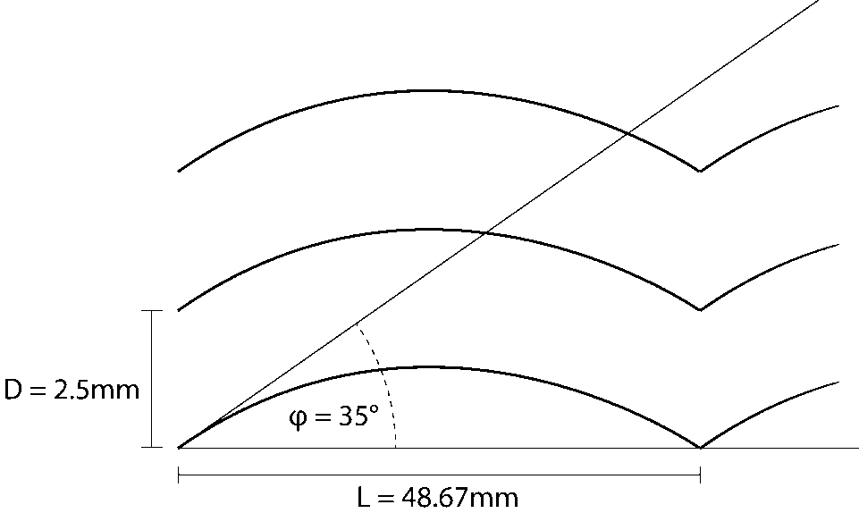
Fig. 3. Primary design parameters for panels A, B, and C.
The intention was to make the angle phi large enough to reflect light from the vertically incoming sunlight and spread it laterally outwards by use of the reflective properties of the laser-cuts. Simultaneously, to avoid reflection of the light in such a way that would result in beams of light reaching below the base of the panel. For the sunlight azimuth angle (in relation to the glass) close to zero, the angle phi should be no larger than 45°, otherwise some beams of light could be reflected downwards. However, since the sun is moving in two axis over the sky, and the laser cutter is limited to only making cuts perpendicular to the panels surface, instead to predict which angle phi would create good or perfect result, the study was designed to test which impact the increase of phi angle has on the final result.
An additional set of patterns (see P1, P2, and P3 in Fig. 4) was created that did not use the linear Edmonds panels as a starting point. Using the software Rhinoceros with its Grasshopper plugin, these panels were created parametrically using ray-tracing to attempt calculating the optimal pattern that would ensure the most even spread of light to every point of the ceiling, given a specific angle of incidence, azimuth, and size of room. By calculating a pattern using very specific inputs, these patterns do have several limitations and would need to be recalculated and designed for every unique situation while the other patterns could be mass-produced and used for the entire building. See Fig. 4 for illustration of all patterns created. The more detailed description of the parametric design is included in the appendix 1.
Figure 4
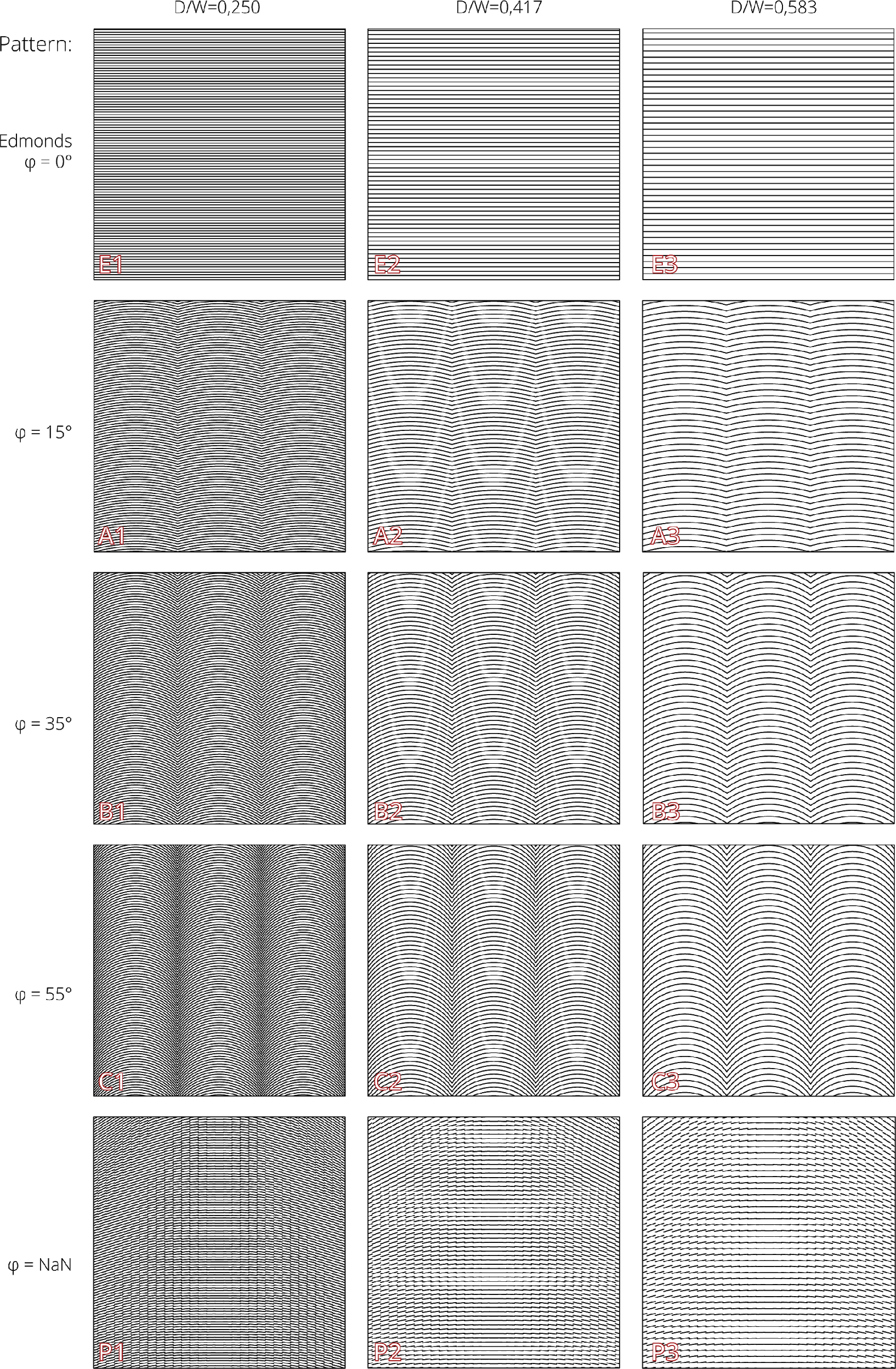
Fig. 4. Overview of the patterns used in this study.
The study has been carried out using the university’s laser-cutter, produced by Hans Yongming, 2011 model with Computer Numerical Control, and the 150×150×6 mm acrylic sheets. The patterns were cut into the material covering 146×146 mm of the surface, leaving a 2 mm border on each of the four sides for structural integrity of the test-sample.
3.3. Experiment setup and equipment
High Dynamic Range (HDR) imaging was used to capture the data and to evaluate the performance of the panels. A box measuring 300×300×300 mm internally was constructed using 6 mm MDF. A square opening of 146×146 mm was cut out on the front of the box to allow mounting the test-samples. In the centre of the right side of the box, a circular hole with diameter Ø=80 mm was cut to allow the entry of a Nikon D600 camera with a Sigma 8 mm f/3.5 EX DG Circular Fisheye lens on a tripod (Fig. 5). The box was then placed on a table in front of a lamp simulating sunlight, i.e. the Sunlight simulator at NTNU, Department of Architecture and Technology, in the distant of 1.8 m. The Sunlight simulator is made of a Fresnel lens with diameter of 800 mm and a point formed, LED-lamp (80 W, 0.32A/230V) delivered by Spectrocolor in 2015. The LED is mounted precisely at the focus point of the lens. In this way the Sunlight simulator generates, similarly to the real Sun, parallel light beams inside a circle of about 600 mm diameter. The Sunlight simulator is mounted on an up-down moving arm with a leveler enabling precise measurement of the elevation angle i.e. the incidence angle α of light on the sample. The box, table and the Artificial Sun were positioned to make sure the centre of rotation was centred on the centre of the test sample (Fig. 6).
Figure 5
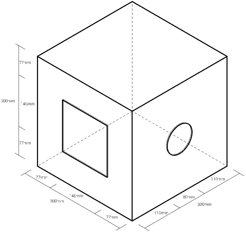
Fig. 5. Isometric view of the test stand box with design parameters.
Figure 6
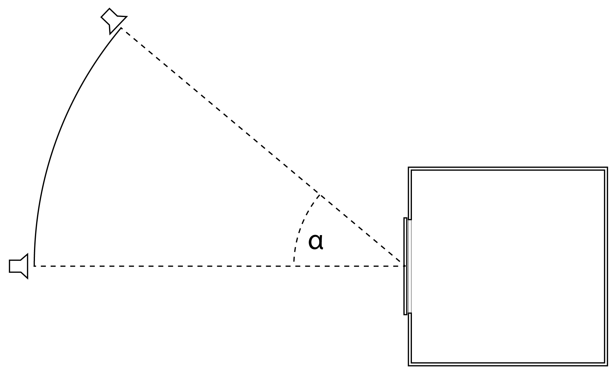
Fig. 6. Side view of test stand box showing how the centre of rotation is centred on the middle of the test-pattern-panel. The size of the Artificial Sun as well as the distance to the box has been greatly reduced for clarity.
A 3×3 mm square of grey-card was placed in the centre of the wall opposite the camera as a target for camera focus and external luminance measurements when calibrating the HDR images. A Konica Minolta Luminance Meter LS-160 was used.
3.4. Equipment Calibration
To obtain correct luminance-data the HDR-images needed both calibration from an externally measured target (grey-card) and calibrating for the luminance loss due to vignetting of the lens. Since the amount of luminance-loss due to vignetting increases as the aperture increases, aperture value of F22 was chosen to reduce the effect of vignetting and to increase the sharpness of the images at the extremities of the fish-eye lens.
To calibrate for vignetting the following steps were taken: The camera was placed on a stationary tripod with a tool measuring the camera’s angle of rotation, and adjusted so that the point of rotation coincided with the camera’s point of no-parallax. A grey-card was placed on a vertical surface (3 meters) in front of the camera perpendicular to the camera and its optical axis. A HDR image was captured at every 5° increment from 0° to 90° in constant lighting conditions (Fig. 7) [10].
Figure 7
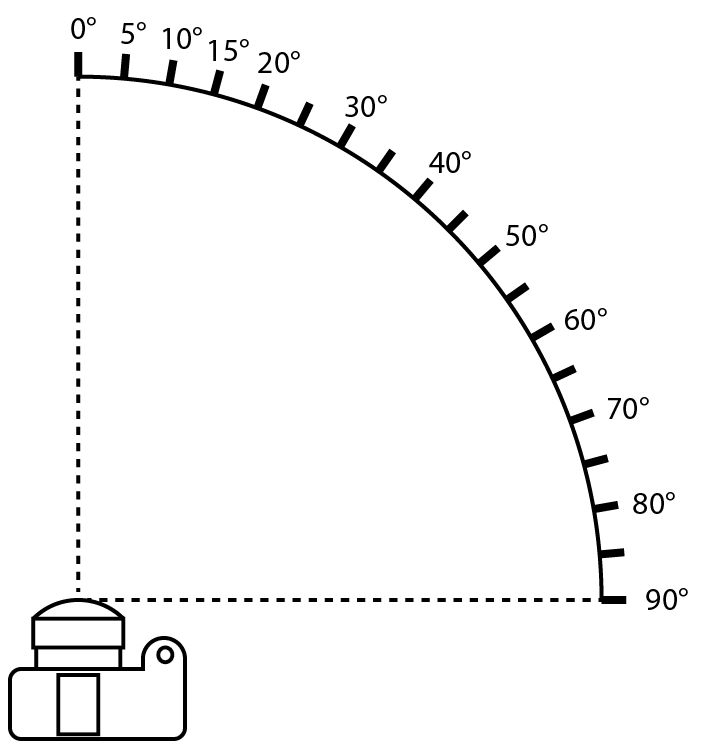
Fig. 7. Calibrating procedure for the luminance loss due to vignetting of the lens.
The first (0°) HDR photo was stitched together in Photosphere and calibrated against the externally measured value of the grey-card and updating the camera-response curve. That same response curve was then used for every following HDR image with the deviation between the expected value of the grey-card and the given value through the HDR image was noted, normalized and plotted in a graph. Using regression, the following polynomial was found to describe the light-loss through the system:
where x is the angle from optical axis. Using a python script this polynomial was translated into a masking file for use with hdrscope’s internal vignetting-mask function. The python script and the vignetting calibration test results are accessible from the authors upon request.
3.5. Image capture and HDR production
Mounting the panel on the box’ front opening, the primary luminance data was captured through a series of HDR images. One HDR image was captured per panel-design per angle of incidence evaluated with additional HDR images with no panel in the opening captured as reference. This resulted in 16 HDR images for every angle of incidence measured, totaling 96 HDR images. Each HDR image comprised of 11 photos of increasing exposure as high-quality HDR images require multiple exposures for higher accuracy. During capture, the camera was tethered to a laptop using Nikon Camera Control Pro 2 software, allowing changing settings manually between each exposure without disturbing the test setup [11].
With the light source in its α=0° position, the camera settings for image 6 was found, making sure the settings provided balanced and proper exposure in the current light conditions, with the aperture of F22 as a fixed condition. The shutter speeds for the rest of the images were determined by increasing shutter speed by 3 steps per image (1-5) or decreasing shutter speed by 3 steps per image (7-11) while keeping ISO value (Table 1). The images were captured using high quality JPEG-compression, Adobe RGB colour space, and a 3700 K white-balance.
Table 1
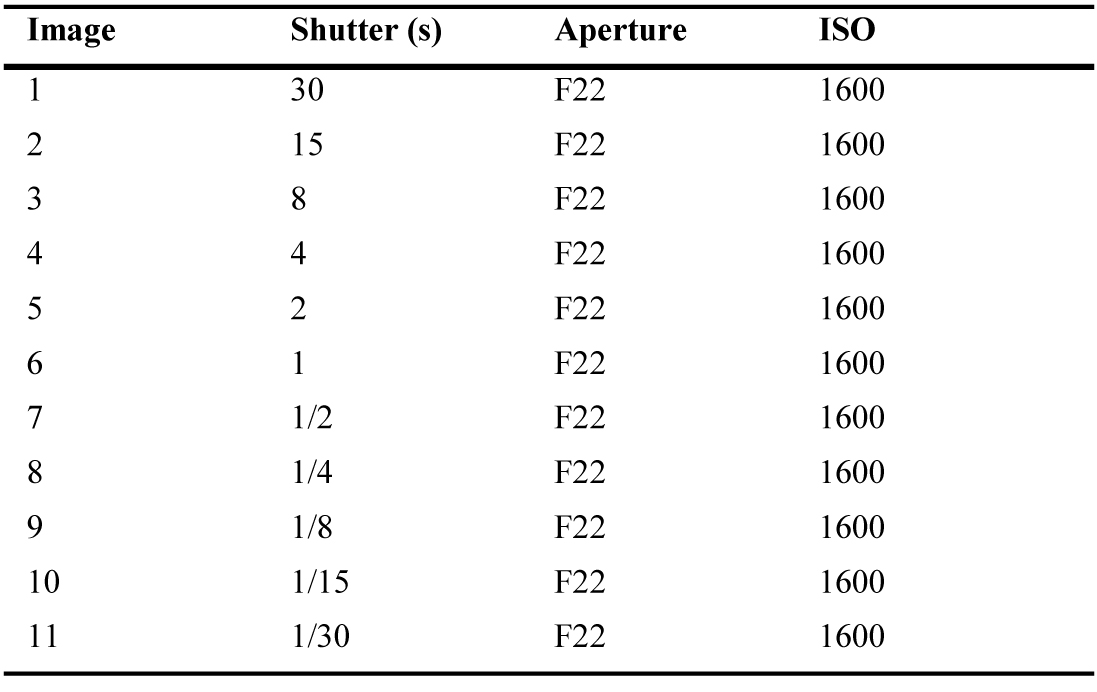
Table 1. Camera setting for each image combined into the final HDRs.
Five points of luminance data of the grey-card opposite to the camera were measured externally and averaged for every angle of incidence evaluated. This measurement was made from the camera’s point of view after all images had been captured. Each set of 11 photos captured per data point were stitched together in Photosphere and calibrated against the externally measured value of the grey-card, and exported as an image file using the HDR Radience RGBE-format for analysis in hdrscope. Once opened in hdrscope the HDR images were calibrated for any vignetting-loss using the vignetting-loss masking file created as previously explained.
3.6. Light distribution estimation method
A new estimation method for the light distribution in a room has been developed for this study. It is based on the analysis of false colour images developed from HDR images. The main principle is to compare the mean luminance of the surface area where the light is wanted if the certain goal is to be met (i.e. upward deflection or the sidewise spreading) with the mean luminance of a larger area considered an obvious reference.
Luminance data was gathered with hdrscope’s analysis function using image-masks to designate appropriate areas (Fig. 8). The area of the room besides the window wall, area R (in orange), was used to consider the total luminance that entered the simulated room, excluding the front wall and panel to prevent glare into the camera from affecting the results. When estimating the panel’s ability to deflect light upwards, mainly towards the ceiling, the area U (in blue) was used and defined as the upper part of the area R, cut off at the centre-line of the panel. The area T (in green) was used to estimate panel’s ability to spread light sidewise specifically beyond the width of the panel itself and was defined as the part of area U beyond of the panel’s width. Consequently, two factors have been defined, the deflection and the spreading factor, in the following way:
where A(R), A(U), and A(T) are sizes of areas R, U, and T, respectively. L(R), L(U), and L(T) are mean luminances across areas R, U, and T, respectively. Table 2 contains the calculation results for light deflection and light spreading factors.
Figure 8

Fig. 8. Evaluated areas: (a) area R marked in orange, (b) area U in blue, and (c) area T in green.
Table 2
Table 2. Deflection of light through the panels.
Table 3

Table 3. Spreading of light through the panels.
4. Results
The deflection and spreading factors calculated for all samples (shown in Fig. 4) can be found in Tables 2 and 3 and on Figs. 9 and 10. The data shows indication of what we already know from earlier studies of LCPs. The panels with the lowest D/W-ratio show the best performance at lower angles of incidence but start losing performance as the angle of incidence increases beyond their range of operation. Around α=30° panels with D/W=0,417 start out-performing D/W=0,250 panels, and panels with D/W=0,583 outperform the rest around α=50° (Fig. 9). P1 shows the highest deflection factor at α=20°, and P2 shows the same at α=30° and α=40°. This indicates that parametrical design techniques can work well for specific situations.
Figure 9
Fig. 9. Light deflection factor.
Figure 10
Fig. 10. Light spreading factor.
At α=0°, any light deflected is due to scattering when the light hits the back wall of the test-box. Comparing the results with measurements made with no panel in the front of the box, indicates the overall luminance-loss throughout the system. Panel C1 shows most absorption, scattering, and loss of luminance closely followed by P2, C2, and P1. This is not unexpected, as the panels with the highest density of cuts throughout the material will introduce more particles, impurities, and imperfect surfaces in the material. As a side-effect from C1 having such a high level of scattering, the panel shows near-linear performance as the angle of incidence increases as one would expect from a completely diffuse material. This indicates that the limit of high-density cuts in acrylic, while retaining the panel’s ability to deflect light, has been reached with this study’s machining techniques.
The panel’s ability to horizontally spread light beyond the width of the panel itself is closely related to the magnitude of curvature in the wave pattern. All Edmonds panels show the lowest ability to spread light with a slight increase in E1 at α=50°, as light is deflected both towards the ceiling and to the floor, scattering back into the room.
B-panels, C-panels and P-panels show great ability to spread between α=0° and α=20°, with C1 and C2 having the best performance in this region. As the angle of incidence increases beyond α=20° B, C and P-panels spreading factor stop increasing and flattens just below SL=0.600. It appears that the panels’ ability to spread light is closely related to their design and while there is gradual increase in spreading of light for the initial 20° measured, angle of incidence does not seem to have significant effect beyond those first 20°.
A spreading factor SL of 0.50 implies an equal amount of luminance inside and outside the width of the panel, and this metric alone would indicate an even spreading of light across the upper half of the room but this metric fails to capture potential issues with hotspots and glare. The false colour images in Fig. 11 show the light distribution at α = 20° for the panels with D/W=0.250. B1, C1, and P1 have the highest spreading factors but may introduce other issues as both panel C1 and P1 may cause glare from the panel to observer depending on mounting conditions and placement of panel in the room. They are also the panels showing the strongest ability to spread light to the side walls due to having high curvature in their design. Panel A1, B1 and E1 show strong ability to deflect light but leave hotspots on the floor and lower wall that may be problematic if the luminance level of the hotspot and surrounding room is too high.
Figure 11
Fig. 11. Overview of selected panels performance.
5. Discussion
Glare is an essential issue with LCPs as a daylighting system because it primarily deflects light without diffusing it. This study attempted to consider the issue of glare using glare analysis tools such as Evalglare but having low-light conditions and a simulated scale-model-room made glare indexes such as DGP report results outside the scope of the proven model [12].
Seeing this, we may instead estimate the risk of glare in a simplified way. The perception of glare depends on the adaptation luminance [13,14]. As the rear wall seen from the centre of the opening hole makes about 53° view angle, see dimensions in Fig. 5, we can consider the average luminance of the rear wall as the adaptation luminance (Fig. 12).
Figure 12
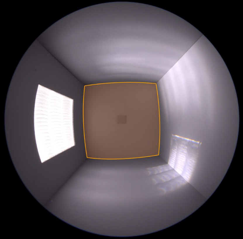
Fig. 12. Mask used in calculation of adaptation luminance.
Such defined adaptation luminance varies from about 1.2 cd/m2 for No panel to about 2.2 cd/m2 (light blue colour) for rooms C1 and P1, (Fig. 11 and Table 4). The respective estimated glare thresholds estimated from [13,14] are shown in the Table 4.
Table 4
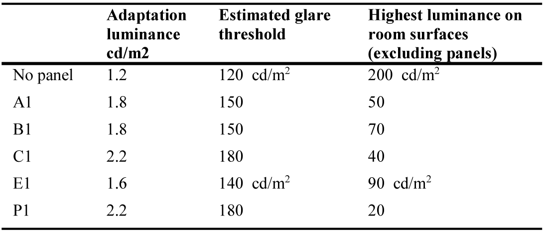
Table 4. Estimation of glare risk at the images from Fig. 11.
As the luminance of the light patch on the wall of No panel reaches 200 cd/m2 we may claim that the glare risk for No panel is high. On the other side, there is no area with luminance higher than thresholds for all other panels. E1 panel generates the second lowest adaptation luminance and the highest luminance in the room; something that allow us to claim that of all panel alternatives the glare risk is highest for E1.
One strategy to minimize the glare risk from LCPs is to avoid the deflected light beam to fall on the occupants, for example by installing the panel on an operable device, which allows adjustment of sloping angle in accordance to the position of the sun [5]. This may still cause light patches of very high luminance on the room’s surfaces but if operated correctly, can deflect light patches outside the views of occupants in the room. If such patches appear in the visual field of an office worker, it can create a very strong luminance contrast, something that are generally not appreciated by users [15].
Another strategy, applied in the present study, is to spread deflected light to the sides. The study shows that this strategy is promising as the highest luminance in the room, with exception of 10° incidence angle, is significantly smaller for A1, B1, C1 and P1 than in the case of the original Edmonds panel E1, Fig. 11. A further study using full-scale panels in a real-world setting would have to be done to provide comprehensive data.
It should be mentioned that the evenness of the light patches generated by the A and B panels on the room surfaces (Fig. 11) can be simply improved by increasing the distance to the wall. In a real building the length of the waves in panels A, B and C, if kept at the similar size of about 50 mm, will be considerably smaller compared to the size of the window, e.g. 20 waves can be created in the 1.0m wide window glass. Consequently, the wave shapes of light patches will overlap much more creating more even illumination.
We also notice high luminance levels on the surface of the panels, especially on panels C and P. It has to be emphasised that in real buildings, contrary to the present experiment setting, the panels will be positioned well above the eye-height, which means that they will not be looked at from the places which they are supposed to illuminate, as in this study, therefore the surface of panels (A, B, C, P or E) as such is unlikely to cause glare.
This study’s method of production and tooling of LCPs have shown to reach limits in cut-density of the panels. Improving these methods could allow the production of panels like C1 without losing its ability to deflect light in a specular manner instead of diffusing the light. With ever evolving technology in laser-cutters and commercialisation of these tools and processes, there now exist laser-cutters that can move on more than three axes and are no longer restricted to cutting materials perpendicular to the material surface. These tools will open for new possibilities with production and research of LCPs and advanced patterns, and may provide even better specialisation for panels custom designed to fit a specific environment such as the P-panels.
Panels A, B, and C and E all have patterns that could be repeated indefinitely and mass-produced with relative simplicity. These patterns all consist of cuts that span the entire width of the panel, reducing the panel’s structural integrity to the border, 2 mm in the present study, to keep the test panels together. This would not be viable for a repeated pattern on a large sheet, but reducing the laser’s cut-power and not have the cuts penetrate the entire thickness of the material would allow large sheets of LCPs while still retaining structural integrity. An installer could specify the size of the panel needed and cut it from pre-produced sheets, creating a simplified installing process rather than custom design patterns and panels for every new room.
Another possibility could be to divide the long cut lines in panels A, B or C into short stretches (e.g. one-two cm) allowing small areas of no-cut in between, similarly to the way it was done for P panels. The break could be done in the area where the waves meet. In addition, a small up-down displacement between the vertical areas of a single wave could be considered. Such solutions could enable the panels A, B, and C to be produced on large sheets allowing free choice of form and size after production and avoid requiring a border around the panel.
One of the possibilities that should be also considered for real building use is angling the panel inward into the room by 10-20 degrees, especially during periods of low sun. In this way, the angle of incidence would be increased correspondingly, improving both the light deflection and the light spreading factors.
Another possibility could be to use a laser-cutter which enables cuts in sloping angles instead of cutting normal to the surface. In this case a sloping angle of cuts could be optimized for the latitude, e.g. 7° slopping was calculated as optimal for an office building in Sandvika near Oslo 59°N [5,6].
As one of daylighting experts discussed, in an ideal world, the laser cut pattern would be adaptive to the position of the sun, and could be adjusted for instance every hour. The dynamic change of the cut geometry in nowadays materials is not possible but a 'most optimum' design solution(s) can be found using multi-objective optimisation with regard to relevant daylight metrics as deflection factor and spreading factor.
The ceiling of the room could also be included as a part of the lighting design. According to [16], a chamfered or curved ceiling can improve the light distribution in the room illuminated by daylight passing through the LCPs significantly. Adjustment of the sloping of the ceiling, or a part of it, quarterly or monthly, could significantly increase the time when daylight level and distribution is optimized.
All studied alternatives, including original Edmonds panels, contribute strongly to “brightening” of the interior, i.e. the ceiling, the wall opposite to the window, the floor and the rest of the room surfaces has significantly higher luminance compared to the scenario No panel (Fig. 11) for all light incidence angles. In the previous studies [15] we learned that the luminance level on room surfaces has impact on the perceived quality of the space. Shortly, in a typical apartment room the increase of a mean luminance on the most visually exposed surfaces contributes to increase of spaciousness, legibility, and friendliness of the space. In a real building, the LCP may be combined with a view-window positioned at the eye level. In the case, this effect will be proportional to the size of the LCP.
4. Conclusions
The intension of the study was not to find an optimal solution for a specific location and/or climate, but rather test new design ideas (like the waveform) and methods (distribution of reflected light evenly over the ceiling using parametric design). We were curious to find which parameters were the most important ones and in which way they influenced the light distribution.
The results of this study indicate that deflecting of light is closely related to the panels’ D/W-ratio and the panels’ ability to spread light is related to the magnitude of curvature in the pattern-design. All panels create areas of hotspots, being potential issues of high luminance contrast in the room. Anyhow, the simplified glare analysis points that all panels developed could generate lower glare risk than the original Edmonds panels.
Evaluating overall performance of the panels over a wider range, A- and B-panels show to be relatively consistent. These panels incorporate both the Edmond panels’ ability to deflect light and the curved design’s ability to spread light, without incorporating too much of the downsides of either design. Parametrically designed panels P-series show great potential in performance but lack the ability to be applied in multiple scenarios.
For rooms where the maximum deflection is crucial for rather low angles of incidence (20-30° as is common situation in Nordic countries in spring and autumn), A1 and P1 could be used; in rooms where maximum deflection is needed for high incidence angles (40–50° average at lower latitudes) P2 and A2 are best, following by C3 and other *3 panels.
In rooms where maximum spreading factor is needed, all panels from C, B and P series could be considered.
The application of the LCPs in real buildings will have positive influence on the perceived quality of interiors, as they will contribute to more spacious, more legible, and friendlier (nicer) spaces.
The paper presents a newly developed estimation method of light distribution in interiors based on the usage of the HDR photography and two new metrics, light deflection factor and light spreading factor, which proved to be very useful.
Acknowledgment
The study was done with the support of Norwegian Research Council and the Norwegian University of Science and Technology.
Contributions
All authors are contributed equally.
References
- I. R. Edmonds, Performance of laser cut light deflecting panels in daylighting applications, Solar Energy Materials and Solar Cells 29 (1993) 1–26. https://doi.org/10.1016%2F0927-0248%2893%2990088-k
- I. Edmonds and P. Greenup, Daylighting in the tropics, Solar Energy 73 (2002) 111–121. https://doi.org/10.1016%2Fs0038-092x%2802%2900039-7
- I. Edmonds, Daylighting high-density residential buildings with light redirecting panels, Lighting Research & Technology 37 (2205) 73–84. https://doi.org/10.1191%2F1365782805li130oa
- R. Labib, Improving daylighting in existing classrooms using laser cut panels, Lighting Research & Technology 45 (2012) 585–598. https://doi.org/10.1177%2F1477153512471366
- N. Ruck, Daylight in buildings, A source book on daylighting systems and components IEA SHC Task 21, July 2000.
- H. Arnesen, Performance of Daylighting Systems for Sidelighted Spaces at High Latitudes, NTNU PhD dissertation, 1999.
- B. Matusiak, Daylighting in linear atrium buildings at high latitudes, NTNU PhD dissertation, 1998.
- B. S. Szybinska, Daylighting is More than an Energy Saving Issue, Energy Efficient Buildings, Jan. 2017. https://doi.org/10.5772%2F65866
- P. Jara, B. Matusiak, Toward new design of laser cut panels for scattering of sunlight at high latitudes, in: Proceedings of PLEA 2017 conference, Edinburgh, 2017.
- M. Inanici, Evaluation of High Dynamic Range Image-based Sky Models in Lighting Simulation, LEUKOS 7 (2010) 69-84.
- E. Reinhard, W. Heidrich, P. Debevec, S. Pattanaik, G. Ward, and K. Myszkowski, High dynamic range imaging: acquisition, display, and image-based lighting, Morgan Kaufmann, 2010.
- J. Wienold and J. Christoffersen, Evaluation methods and development of a new glare prediction model for daylight environments with the use of CCD cameras, Energy and Buildings 38 (2006) 743–757. https://doi.org/10.1016%2Fj.enbuild.2006.03.017
- N. Baker and K. Steemers, Daylight Design of Buildings: A Handbook for Architects and Engineers, Routledge, 2002.
- R. G. Hopkinson and J. B. Collins, The ergonomics of lighting, Macdonald and Co. Ltd, London, 1970.
- C. Moscoso and B. Matusiak, Aesthetic perception of a small office with different daylighting systems, Indoor and Built Environment 27 (2017) 1187–1202. https://doi.org/10.1177%2F1420326x17711490
- A. A. Freewan, Maximizing the Performance of Laser Cut Panel by Interaction of Ceiling Geometries and Different Aspect Ratio, Journal of Daylighting 1 (2014) 29-35. http://dx.doi.org/10.15627/jd.2014.4
Copyright © 2019 The Author(s). Published by solarlits.com.

420
Total views
Citations
SHARE ON


