Volume 6 Issue 2 > pp. 80-96 • doi: 10.15627/jd.2019.9
A Review on Solar Concentrators with Multi-surface and Multi-element Combinations
Xinglong Ma,a Hongfei Zhenga,*, Shuli Liua,b
Author affiliations
a School of Mechanical Engineering, Beijing Institute of Technology, Beijing 100081, China
b School of Energy, Construction and Environment, Coventry University, Coventry CV1 2HF, United Kingdom
* Corresponding author.
hongfeizh@bit.edu.cn (H. Zheng)
baalxmxl@yeah.net (X. Ma)
aa6328@coventry.ac.uk (S. Liu)
History: Received 11 July 2019 | Revised 28 September 2019 | Accepted 3 October 2019 | Published online 9 October 2019
Copyright: © 2019 The Author(s). Published by solarlits.com. This is an open access article under the CC BY license (http://creativecommons.org/licenses/by/4.0/).
Citation: Xinglong Ma, Hongfei Zheng, Shuli Liu, A Review on Solar Concentrators with Multi-surface and Multi-element Combinations, Journal of Daylighting 6 (2019) 80-96. http://dx.doi.org/10.15627/jd.2019.9
Figures and tables
Abstract
Solar concentrator always plays an important role in solar energy collection as it could enhance the energy density effectively. Various structures of solar concentrators have been researched in recent years, among which multi-surface (MS) and multi-element (ME) combinations are the two typical structures. MS concentrator is an improved structure for single surface concentrator. It is usually designed to increase the acceptance angle, enhance the light intercepting efficiency, homogenize the energy distribution, etc. ME concentrator is generally consist of two or more optical elements, in which MS concentrators are usually used as assistant optical components. ME concentrator always has larger tolerance on tracking error so that it is much easier to track the sun. It could be applied in high power concentration. The combination on optical elements of MS and ME solar concentrators was diagramed and theirs advantages and disadvantages were evaluated. Nowadays, solar applications are becoming more and more diverse and concomitantly, the researching methods are also improving. The computer-aided methods including numerical computation and optical simulation are the dominant method in nowadays, which makes it easier to analyze various structures of solar concentrators and their complex applications. Besides, solar applications are not limited in CT and CPV, but in many other fields such as solar daylighting, solar-pumped laser, solar cooling, solar desalination etc. It has been believed that more and more innovative designs on solar concentrator will be proposed in the future.
Keywords
Solar Concentrator, Multi-surface combination, Multi-element combination, Special-shaped solar concentrator
1. Introduction
Solar concentrators are efficient devices that used for collecting the low-density solar energy to obtain high-quality energy. Reflectors with parabolic surfaces and lenses with convex-shaped surfaces are the two main type of concentrators, which have been used for solar concentration since earlier time. From 1980s, some of European and American countries built several solar power plants with parabolic trough concentrators (PTC) [1]. However, the power plants were not managed very well in commercial level, especially in developing countries, due to some demerits of PTC when it is used in practices, such as large wind resistance, apt accumulation of dust and snow, high requirement of tracking precision, as well as huge energy consumption of driving and operation, etc. [2,3]. Fresnel lens was invented by Augustin Jean Fresnel in 1820s and used for beacon [4]. Unlike ordinary lens, Fresnel lens has large aperture and thin thickness, for which it has several advantages such as small volume, low material cost, light weight, small f-number (Ratio of focal length and aperture width), and importantly, effectively increase of the energy density. The development of material technology has promoted the progress of Fresnel lens. Plastics like Polymethyl Methacrylate (PMMA) and Poly Carbonate (PC) are taking the place of glass gradually. Besides, the development of manufacturing is another reason that accelerates Fresnel lens’ application. In 1951, Mill [5] designed and manufactured the world’s first plastic Fresnel lens by injection molding. He found that the plastic Fresnel lens has superior surface as well as the glass material. Even though, plastic Fresnel lenses were not applied in solar field until 1970s, when a large number of researches studied the Fresnel lenses, especially on PMMA and PC materials. Nevertheless, Fresnel lenses were not widely applied on solar concentration due to its intrinsic properties and crucial defects, such as the focal length of the Fresnel lens is not stable, which makes it difficult to receive the concentrated energy [6]; the plastic material is apt to aging and easily scratched, which could not be accepted by industry easily. Some researchers have surveyed systematical information on development of solar concentrator. Xie et al. [7] focused on concentrated solar applications by using Fresnel lenses. The recent developments of imaging Fresnel lens solar concentration systems and non-imaging systems were reviewed. Miller et al. [8] mainly talked about durability of Fresnel lenses used in the concentrating photovoltaic application. Jun Xiao et al. [9] investigated the measuring methods for solar concentrators’ shape and surface. Ahmad Mojiri et al. [10] concentrated on the spectral beam splitting technology for efficient conversion of solar energy. Dhyia Aidroos Baharoon et al. [11] retrospect the development history of concentrating solar power technologies. Reflection-type solar concentrators have been specifically concerned. Srikanth Madala et al. [12] reviewed the non-imaging solar concentrators for stationary and passive tracking applications. Concentrators with large acceptance angle including compound parabolic concentrator (CPC), total dielectric concentrator and some two-stage solar systems have been summarized. Meng Tian et al. [13] introduced the progress in the CPC for solar energy applications. Literatures since 2000 have been mainly reviewed, but there is no systematical discussion on the structure of solar concentrator. A Table lists out the reviewing papers on solar concentration, solar materials, solar cells, light splitting utilization etc. in recent years. With development of solar concentration, single optical element could not always satisfy all concentrating requirements. Some researchers have attempted to change the structural form of solar concentrators. It has been found that combining two or more optical surfaces or elements into one concentrator will achieve better performance. In this paper, a review on solar concentrators with MS and ME combinations was surveyed. Some representative designs, special structures and interesting thoughts were also summarized. MS solar concentrator is presented in section 2. Section 3 presents the solar concentrators with combined elements. Section 4 introduces some special-shaped solar concentrators. Finally, a detailed discussion and perspective are given in section 5.
2. MS solar concentrator
MS solar concentrators are usually comprised of two or more different surfaces. The most popular non-imaging concentrator is known to be the CPC that was firstly used for solar energy by Winston and Hinterberger [14]. CPC is transferred and developed from parabolic concentrator. As Fig. 1(a) shows, though translating and rotating, and cutting off the redundant parts, an ideal structure has been obtained. CPCs are more acceptable for solar energy collection because they can achieve highest concentrated solar energy for any acceptance angle and they have a constant acceptance angle over the entire entrance aperture [15,16]. Figure 1(b) shows the characteristic on the intercept coefficient by changing the tilt incidence. However, CPC is ideal only for the uniform incident solar flux, but nature solar energy is not uniform. The further developed edge-ray principle makes it could be designed much more suitable for the non-uniformity natural light [17]. This change has attracted more investigations on CPC and promoted a wider utilization.
Figure 1
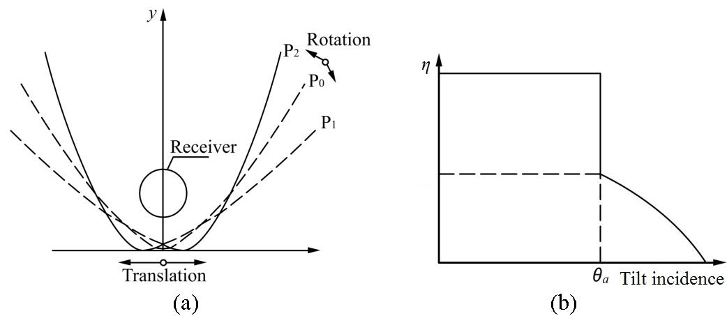
Fig. 1. The structure of CPC: (a) transformation of CPC and (b) characteristic on acceptance of incidence.
Although, CPC has better performance on solar concentration, its weaknesses are also obvious. Comparing to single parabolic concentrator, CPC has higher height and thinner width, so it requires more vertical space. Besides, the acceptance angle is not large enough to make it work without tracking. In this case, many different forms of CPC-type concentrators and new structures have been put into research.
2.1. Double surfaces combination
2.1.1. Reflective CPC-type solar concentrator
In 1996, Gordon et al. [18] put forward a modified CPC collector, tailored edge-ray concentrator (TERC), which colligates translation and rotation and tailoring to obtain optimal reflector contours. The total stationary TERC has around three times of geometrical concentration ratio (GCR), with greater energy delivery. Although TERCs have lower GCR, but has better energy distribution uniformity. So it is mostly used for concentrating photovoltaic/thermal hybrid system (CPV/T). Heat is obtained during the solar cells’ cooling process [19]. However, the high height limited TERC’s acceptance angle.
Yamei Yu [20,21] modified the structure of TERC and then obtained a restricted exit angle CPC (CPC-65), showed in Fig. 2. The single side of CPC-65 is combined by parabolic and flat surfaces. To illustrate the advantages of CPC-65, another concentrator with same optical parameters, without exit angle restriction CPC-90 was designed for comparison. The height of CPC-65 is about 2/3 to CPC-90. The simulative results show that CPC-65 has larger acceptance angle and better uniformity of focal area than CPC-90, and the power output of CPC-65 is also higher. Wandong Zheng et al. [22] designed a CPC-type concentrator, which combines a parabolic surface with an involute surface. The involute surface was used for enhancing the light intercepting ability. Wandong Zheng had investigated the relations among the height, GCR and acceptance angle of the CPC-type concentrator. It concluded that GCR and acceptance angle are negatively correlated to the height of the concentrator. A 30° acceptance angle concentrator with three times of GCR has been experimental tested. The results showed that the thermal efficiency is about 60.5%. Similarly, Jing Dai [23] also designed a concentrator of parabolic surface and involute surface combination, which was used as secondary concentrator for a two-stage concentrating system. The concentrator was designed with a large part of involute surface to reduce the height and widen its aperture width. As the secondary concentrator, a wider aperture width could reduce the requirement of tracking precision and re-collect the deviated lights. However, there is a non-negligible problem during the concentrating process is that there always exists a slit with a certain width between the wall of glass tube and the surface of absorber, from where some off-axis incident lights could escape off. The energy loss caused is called “Gap Loss”. Rachel Oommen et al. [24,25] presented a ‘V’ groove bottom to reduce Gap Loss. The escaped light between the receiver and the bottom would reach to the wall of “V” which would be reflected to the receiver again. This collectors has about 2 times GCR of normal CPC collector and used for stationary water heater.
Figure 2
![Restricted exit angle CPC (CPC-65) [20].](figures/6-80-2.jpg)
Fig. 2. Restricted exit angle CPC (CPC-65) [20].
Some researchers have attempted to enlarge the acceptance angle of the concentrator. The asymmetric CPC-type concentrator (ACPC) has been investigated. As Fig. 3 presented, ACPC is generally comprised of parabolic surface and plane, cylinder or CPC. Parabolic surface is the primary reflector and the other parts are assistant reflectors. The focus is usually design on the nearside of the assistant reflector [26]. Milorad et al. [27] designed seashell solar concentrator for high latitude area. A non-imaging asymmetric stationary concentrator consists of a large parabolic reflectors and a small hemi-circle reflector. A heat adsorptive fin is assembled on the hemi-circle reflector. The experimental result shows that the optical efficiency is about 80% with incident angle of 50°. It can be seen that ACPCs are more available to the single-side-tilt incident rays. Inevitably, the tilt incidence increases the cosine effect, which leads to the decrease in both the lighting area and GCR.
Figure 3

Fig. 3. Asymmetric CPC-type concentrators.
2.1.2. Totally internal reflection solar concentrator
Totally internal reflection (TIR) is another technical route of CPCs’ development. TIR concentrator utilizes total reflection on the mediums’ interface to take place of mirror reflection. Generally, TIR concentrator could be a CPC-shaped vessel that filled with a transparent high index liquid or transparent dielectric solid substance, in which the mechanism for reflection of the sidewalls is totally internal reflection [28]. Figure 4 shows the structure of a TIR concentrator. Actually, TIR concentrator has equal results like transmission-reflection combined two-stage concentrator. Light will be refracted when it is going through the upper interface, so TIR concentrator have larger acceptance angle.
Figure 4
![TIR concentrator [29].](figures/6-80-4.jpg)
Fig. 4. TIR concentrator [29].
Xu Yu et al. [29] designed one kind of miniature dielectric CPC-type TIR concentrator (dCPC). They had found that the lights would only traverse through the bottom of the dCPC when incident angle is less than 20°. When incident angle increases exceeding 20°, some light starts to shoot out through the sidewall. This technology will be a wonderful advantage for building-integrated application. Chaoqing Feng et al. [30] designed a flat plate dCPC concentrator that used for concentrating photovoltaic/thermal/daylighting system. The solar cells are adhered on the bottom of the dCPC. In the early morning and later afternoon, more sunlight is needed for natural indoor lighting, the light will be transferred through the dCPC as the incident angle is much larger than its acceptance angle. During the near-noon time, sunlight supplies sufficiently and the indoor lighting is bright enough to let more natural light into the room the sunlight within the acceptance angle of dCPC will converse the redundant sunlight into electricity. Meanwhile, the hot water was used to store the thermal energy from the cooling process of solar cells.
Cruz-Silva et al. [31] presented one kind of shaped dielectric TIR concentrator. Its upper interface was spherical surface and two sidewalls were figure out by numerical method. It could always achieve maximum concentration so that it was much appreciated to Fresnel-type two-stage system. However, TIR concentrator extends the acceptance angle, with the reflection loss on the upper interface increased. In addition, the solid structure consumes a large mass of material, which obviously increases the absorption loss. Hence, it is not applicable for large size concentrator.
2.2. Multiple surfaces combination
It is similar to two-surface combination, changing the structure of CPC to obtain MS concentrator is still the preferred method. For example, the structure of three-surface combination solar concentrator is shown in Fig. 5. The primary reflector contains section AB and section BC, which are parabolic surfaces generally. The assistant reflector, section CD, is involute surface as it could reflect the light onto the receiver efficiently. For CPV use, CD could be replaced by flat mirror to get better energy distribution. However, some times the three sections are all flat planes, such as multisectional planar concentrator [32]. It has well energy distribution via sacrificing a larger acceptance angle.
Figure 5
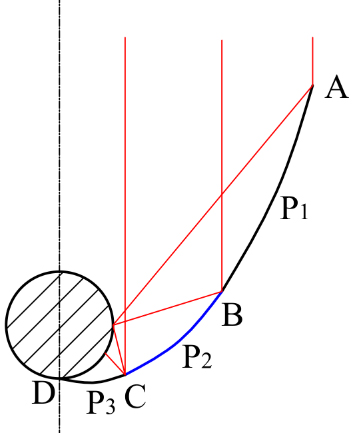
Fig. 5. General 3-surface combination structure.
2.2.1. Asymmetric CPC-type solar concentrator
In 1986, Baum et al. [33] presented a geometric analysis with optimal configurations of asymmetric CPC (ACPC). One side of it is combined by a parabolic and involute surfaces, the other side is a single parabolic surface. This kind of ACPC has compact structure that is very suitable for integrated collector storage solar system. Tripanagnostopoulos et al. [34] designed and tested a solar collector consist of two separate absorbers, which are horizontally incorporated in a stationary ACPC. It has large intercepting area due to the two receivers. However, the low geometrical concentration ratio makes it only could be used for low temperature fields. They also designed an integrated collector storage solar system with a parabolic-involute combined ACPC [35,36]. A comparison between the new ACPC and symmetric CPC had been carried out. The results showed that the new ACPC has lower mean daily efficiency, while it contributes to better water heat preservation during the night compared to the system with symmetric CPC reflector. The optical simulation illustrates that the 100% acceptance angle of ACPC is approaching to ±45º, which means it could be set stationary in a year. Hamdi Kessentini et al. [37] designed an ACPC-CPC integrated solar collector. The ACPC-CPC collector needs no tracking as it has about ±45º acceptance angle. However, the GCR is only 0.86, the highest concentrated temperature is about 65℃. From the above, it can be seen that the main aim of ACPC is to achieve large acceptance angle and thus to realize non-tracking. Thereby, lower the cost of operation and maintenance in actual use.
2.2.2. Multi-surface compound solar concentrator
Multi-surface compound solar concentrator (MSC) is another form of CPC-type concentrator. It is imaging collector, which has high GCR. The structure of multi-surface concentrator is shown in Fig. 6, which is comprised of two paraboloids and one flat mirror [38]. Hongfei [39-41] firstly suggested the structure and design of a solar funnel with GCR of 31. It is used for high temperature solar stove. The highest temperature is about 250℃ with the average collection efficiency is about 43%. The solar funnel needs double-axis solar tracking mechanism with an acceptable tracking error about 2°. Tao Tao et al. [42,43] designed a multi-surface trough based on MSC with GCR of 6. The experimental test on air heating has been carried out. The results indicate that the highest temperature of the air heater with a circular glass receiver could be over 140℃. When the collection temperature is around 60℃, the collection efficiency is about 45%. Natarajan [44] presented a novel gravity based passive solar tracking mechanism for MSC. This tracking mechanism performs well in noontime. The difference between simulated minimum incidence angle and the actually obtained from the experimentation is less than 1°.
Figure 6
![Diagram of multi-surface compound solar concentrator [38].](figures/6-80-6.jpg)
Fig. 6. Diagram of multi-surface compound solar concentrator [38].
2.2.3. Special designed MS solar concentrator
Chigueru [45] presented a 4-surface combination CPC-type concentrator with fully illuminated wedge absorber. It was comprised of three segments of parabolas and one involute curve. This concentrator needs no tracking as it has minimum acceptance angles of 30°. It was used for thermal energy supply of industrial processes that temperatures below or equal to 100 ℃.
Julio et al. [46] design an ultra-flat compact concentrator, which is comprised of a large number of small CPC-like cells arraying side by side as is shown in Fig. 7. These compact designs are much more compact than the traditional ones like lens-mirror combination structure. The acceptance angle could be designed freely and the GCR is relative to the number of the CPC-type cells. However, the complicated structure makes it hard to manufacture and repeated reflections leads to a large decrement of optical efficiency. Secondary concentrators are applied in solar concentrating systems to re-collect solar beams that concentrated by the primary concentrators.
Figure 7
![Ultra flat compact concentrator [46].](figures/6-80-7.jpg)
Fig. 7. Ultra flat compact concentrator [46].
Timinger [47] presented secondary concentrator with non-regular shapes for increasing the concentration of radiation from a given field of heliostats, is well suitable for partitioning the receiver into several units, arranged side by side. It is combined by two CPCs and its entrance and exit aperture could be designed as rectangle or circle, thus obtain different GCR and focus’ uniformity.
Chung-Yu Tsai [48] presented a novel variable-focus-parabolic (VFP) reflector in which the focal length is not fixed, but varies as a function of the horizontal displacement of the incidence point relative to the vertical centerline of the solar cell, presented in Fig. 8. The simulation results have proved that the VFP concentrator guides 98.8% of the incoming lights onto the solar cell and improves the irradiance distribution uniformity by around 92% compared to that achieved by the single parabolic reflector.
Figure 8
![Variable-focus-parabolic reflector [48].](figures/6-80-8.jpg)
Fig. 8. Variable-focus-parabolic reflector [48].
3. ME solar concentrator
Multi-element combination is another kind of solar concentrator, which is very popular for large aperture concentrator. It usually contains two or more optical elements, including primary concentrators and assistant concentrators. It could also be named as multi-stage concentrator. Generally, the primary concentrator could be a PTC, Linear Fresnel reflector (LFR) or Fresnel lens etc. and the assistant concentrator could be a small size PTC, CPC, CPC-type concentrator, TIR concentrator, or even a simple mirror. Because of the large size, structure of primary concentrator is not easy to be maintained perfectly due to the huge weight and environmental factors, the lights could not be concentrated onto a strict focal point or a focal line. Adding assistant concentrator can enhance the intercept efficient as well as lower the requirement of tracking precision. Generally, it can be classified as reflection-type, transmission-type, and hybrid combination.
3.1. Two elements combination
3.1.1. Reflection-type two elements combination
Concentrators used for solar thermal collection are attracting more attention to its intercepting ability so that it could obtain high collection efficiency as much as possible. Figure 9 shows a compact two-stage solar concentrator. The primary is a parabolic and involute surfaces combined structure and the secondary is an involute-surface concentrator. The focus of the primary concentrator could be set on point B and C. The concentrator has a half-acceptance angle of 20°. It can be seen, the height of the concentrator is approaching to the diameter of the receiver, which means that the design is near the highest achievable compactness. Of course, it can also be seen as a combination of two ACPCs introduced in reference [26].
Figure 9
![Compact solar concentrator [48].](figures/6-80-9.jpg)
Fig. 9. Compact solar concentrator [48].
John et al. [49] presented a linear focusing solar concentrator with two reflecting as presented in Fig. 10. The concentrator has a large stationary hemi-cylinder reflector and a small motive elliptical reflector, which is tracking the sun. The deep secondary reflector can reduce convective heat loss due to the wind on the hot fluid pipe is very small. Compare to parabolic reflectors, the two-trough structure has better performance in actual weather due to its stationary primary reflector.
Figure 10
![Two troughs combined solar concentrator [49].](figures/6-80-10.jpg)
Fig. 10. Two troughs combined solar concentrator [49].
The large-size solar concentrators that used for solar power plant mainly are two-stage concentrators and CPCs are chosen as secondary concentrators. Figure 11 shows a typical form of larger-size solar concentrator which consists of a PTC and a CPC. PTC has a perfect concentrating performance theoretically, but it requires high precision for sun tracking. Besides, it is apt to accumulating dust and snow and suffering heavy wind lord due to the upward concave shape. LFR could avoid these weaknesses for it has gaps between every two reflectors [50-53]. However, the receiver of these concentrators is always on top of primary concentrators, which leads to the blocking loss on the back of the secondary. Thereby, the primary concentrator is generally designed much larger than the secondary one to neglect the effect of blocking. Also, another important weakness of LFR is lower, which needs strong frame to support.
Figure 11
![Large-size two-stage solar concentrators [50].](figures/6-80-11.jpg)
Fig. 11. Large-size two-stage solar concentrators [50].
It is different from the concentrating thermal application, secondary concentrators that used for concentrating photovoltaic usually adopt parabolic of flat surfaces take the place of involute surface to get better energy uniformity. As shown in Fig. 12, secondary one with parabolic, hyperbolic, or flat surface could be designed as imaging concentrator. The secondary reflector and the primary reflector can be designed coplanar to keep its structure more compact. Golden [54] had investigated the performance of the two structures on the imaging and non-imaging. He found that non-imaging form has better tolerance for tracking error than imaging form, but its GCR is relatively less.
Figure 12
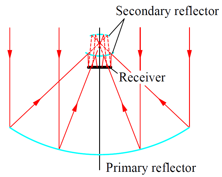
Fig. 12. Imaging two-stage concentrator.
Xianlong Meng [55] designed symmetrical two-stage concentrator using a flat mirror as the secondary reflector. The primary reflector are two parabolic solar dishes, which can be design separately. In addition, the GCR could be increased by adding the numbers of primary reflectors. The flat secondary mirror reflects the concentrated light down to the receiver that is set on the ground. The disadvantage of this structure is that each of the solar dish needs an independent tracking. Qiang Cheng [56] used a large aperture PTC as the primary concentrator and a less aperture PTC as the collimated reflector. The light distribution on the solar cells is uniform. Unfortunately, a dark area occurs near the center plane due to the blocking of secondary reflector, which leads the receiver to be divided into two parts. Xianlong Meng [57] designed a special structure secondary reflector to solve the blocking. He proposed a novel free-form Cassegrain secondary concentrator for PV/T hybrid utilization. As Fig. 13 shows, the secondary concentrator is combined by parabolic and hyperbolic surfaces. The radiation in the center is used for high temperature thermal collection and the remaining heat flux around the edge of focal spot is directed to the solar cell for electricity generation. The maximum GCR for PV receiver is about 40, and is about 2215 for thermal receiver. Kok-Keong Chong et al. introduced a latitude-orientated mode of non-imaging focusing heliostat (LO-NIFH) using spinning-elevation tracking method. The primary concentrator is a heliostat array and the secondary is a square conic-shaped collector. One of the most important merits is that it makes a heliostat operating at a very narrow range of incident angles ranging from 0° to 52° for 14h of tracking time per day. The optical efficiency is above 88% [58]. The secondary can also be CPC-type structures [59,60]. A similar type is non-imaging dish concentrator (NIDC). The difference is the primary concentrator is a dish-shaped reflectors array. In addition, the secondary concentrator could be CPC, CPC-type, or TIR collectors [61-63].
Figure 13
![Free-form Cassegrain concentrator [57].](figures/6-80-13.jpg)
Fig. 13. Free-form Cassegrain concentrator [57].
Mahmoud Abdelhamid [64,65] presented a new CPV/T structure to avoid the blocking loss of secondary concentrator. A small-scale CPC is put into the glass tube receiver together with the working fluid pipe. Both of the back and front of the CPC are adhered solar cells so that the blocked light could be reused. The experimental results illustrate that thermal efficiency is about 37% at 365℃ and electrical efficiency is about 8%. The total system electricity generation is around 25% of incoming DNI, by assuming under high temperature stream. While the disadvantage of this system is that electricity conversion efficiency of GaAs solar cells is too low as the working temperature of the solar cells is too high. Sheng Wang [66] presented a hybrid solar energy system, which combines the advantages of concentrated solar power technology and high performance concentrated photovoltaic cells, shown in Fig. 14. On one hand, the secondary reflector has double reflective surfaces. The convex surface is used for reflecting the converged rays that come from the primary reflector to the bottom solar cells. On the other hand, the concave surface reflects the center incoming rays to the pipe receiver. The working fluid could be heated by the waste heat of the solar cells and the secondary reflector simultaneously.
Figure 14
![Two sides reflection of secondary reflector [66].](figures/6-80-14.jpg)
Fig. 14. Two sides reflection of secondary reflector [66].
Another special application is solar collectors combined with solar stills. The difference is the solar concentrator is not directly compounded with solar still. Thus, the water inside the solar still is heated by both solar still itself and the solar concentrator. Also, the phase change material was used for retaining the redundant heat in daytime [67,68].
3.1.2. Transmission-type two elements combination
The blocking loss mentioned in the section 3.1.1 of reflective combination concentrator could be completely solved by transmission-type combination structures. In 1976, Pereira et al. [69] described lens-mirror combination structure that contains a lens and a couple of elliptic mirrors, shown in Fig. 15. The concentrator can collect all radiation incident on the lens aperture AA1 with incident angles no more than θa. Similarly, another structure uses a flat plate Fresnel lens for taking the place of convex lens. Lens-mirror combination concentrator has an f-number of approximating to 1.0, which is much smaller than a single CPC’s.
Figure 15
![Lens-mirror combination concentrator [69].](figures/6-80-15.jpg)
Fig. 15. Lens-mirror combination concentrator [69].
Nelson [70] designed a line-focus Fresnel lens solar concentrator with a CPC-type secondary, which was used for heating water. The illustrated temperature could reach to 143℃ and the daily collection efficiency is about 50%. Xinglong Ma [71] combined cylindrical Fresnel lens with folding plane secondary reflector. The maximum and minimum thickness of cylindrical Fresnel lens is 7 mm and 2 mm respectively. The aperture width is 650mm, which archives a GCR of 9.2. The intercepted optical efficiency is about 0.84.
It is effective to enlarge acceptance angle and increase intercept coefficient by combining Fresnel lens with secondary reflector, while the energy distribution is generally not uniform enough for solar cells. Muhammad Burhan [72] designed a CPV system by taking a large convex lens as primary concentrator and a little concave lens as secondary re-director. The energy distribution in the focal area is highly uniformed. The generated electricity was used for electrolytic hydrogen. The maximal solar to hydrogen efficiency is 18%.
Fresnel-Köhler (FK) system is one of typical transmission-type two elements combined system. FK system is comprised of Fresnel lens and Köhler integrator, a special designed TIR concentrator. Ling Fu et al. [73] designed several refractive TIR concentrators with different shapes that used as the optics under the same Fresnel lens to analyze their optical performances, as presented in Fig. 16. It has been found that statistical mixing offers higher flexibility for the solar application. The half-egg shaped secondary can always re-concentrates the light onto the center area of the secondary. Thus, different cut structures could be derived from the half-egg shape to decrease the material and easy theirs manufacture.
Figure 16
![Shaped-TIR concentrator for FK system [73].](figures/6-80-16.jpg)
Fig. 16. Shaped-TIR concentrator for FK system [73].
Pablo Zamora and Rubén Mohedano et al. [74,75] had made further improvement on FK system. The Fresnel lens and TIR-type secondary concentrator were designed non-rotational symmetric structure, shown in Fig. 17. This FK concentrator module has outstanding geometrical concentration and better irradiance uniformity. The optical efficiency is about 0.85 and the electrical efficiency is up to 32.7%. They also designed a dome-shaped FK concentrator [76,77]. Comparing to normal FK concentrator, dome-shaped FK concentrator has higher concentration-acceptance product and thus it has better optical performance. Besides, they have found that f-number is an important factor of transmission efficiency. Although the FK concentrator enhances the performance, it increases the adsorption loss, system cost and difficulty of installation. Alex Goldstein [78] put forward a wineglass-like concentrator, which combines a dual-mirror aplanat to an aspheric plano-convex lens. Raytracing confirms that dispersion losses here are negligible when the lenses comprise glass or acrylic (n=1.5, integrated over the terrestrial solar spectrum). If the acceptance angle decreases to 1°, the GCR of modified non-imaging design would reach 1060.
Figure 17
![Non-rotational symmetric designed FK system [74].](figures/6-80-17.jpg)
Fig. 17. Non-rotational symmetric designed FK system [74].
3.2. ME combination
3.2.1. Reflection-type ME combination
One of the remained two-stage solar concentrator in the section 3.1.1, LFR concentrator, generally have inferior performance due to losses in the mirror field. These include blocking of reflected radiation and shading of adjacent mirrors from incoming radiation. To solve this problem, Mills et al. [79] put forward compact linear Fresnel reflector (CLFR) which is suitable for large-scale solar thermal power generation plants. A CLFR system creates multiple receiver targets for the reflectors to reduce optical losses in adjacent mirrors. Another advantage of this structure is that it avoids the block of secondary reflector due to the secondary reflectors were set aside of the linear reflector field. Rungasamy [80] proposed that receiver of CLFR could be modified by including an etendue conserving mirror field as opposed to a flat field. Etendue was used as an indicator of the losses within the system and therefore the optical optimization of the mirror field seeks to conserve incoming etendue. This could be done once for peak conditions and subsequently fixed with mirrors rotating throughout the day; or the mirror axis points could also be allowed to move up and down throughout the day, creating new etendue conservation curves.
Mordechai Lando [81] designed and constructed an astigmatic corrected target-aligned (ACTA) solar concentrator, which was comprised by three parts. As Fig. 18 shows, a 3.4 m diameter primary mirror, composed of 61 segments, was mounted on a commercial two-axis positioner. A four-segment plane mirror reflects the light towards a horizontal focal plane. In addition, a CPC secondary was used as the third stage concentrator. Peak solar concentration in the focal plane exceeded 400 suns. It rendered the ACTA configuration an attractive option for future high concentration solar energy collector. ACTA tower configuration may also be compared to a furnace design.
Figure 18
![ACTA solar concentrator [81].](figures/6-80-18.jpg)
Fig. 18. ACTA solar concentrator [81].
Hongfei Zheng et al. [82] designed a solar daylighting system by combining three MSC concentrators as shown in Fig. 19. The primary concentrator is a MSC funnel. CPC 1 is a collimator and CPC 2 is a re-concentrator that used for reflecting lights into the fiber. The experimental results showed that this solar fiber lamp could provide a brightness of a 6-8 W electrical energy-saving lamp with the entrance diameter of the primary funnel is 0.2 m2. Muhs [83,84] described a system that collects and distributes the visible portion of sunlight using large-core optical fibers and combines it with electrically generated light in existing light fixtures, expressed in Fig. 20. An intelligent control strategy was adopted to accommodate lighting requirements in nighttime or cloud cover. A different solar PV/T configuration suggested by Horne [85] involved a Cassegrainian system in which a parabolic primary reflector and a hyperbolic secondary reflector directed solar radiation in through a window of a black body cavity. As illustrated in Fig. 21, the cavity has a parabolic ceiling, which provided more uniform illumination of the emitted light and redirected the light towards PV cells attached to a flat wall at the back.
Figure 19
![Three MSCs combination [82].](figures/6-80-19.jpg)
Fig. 19. Three MSCs combination [82].
Figure 20
![Intelligent solar lighting system [83].](figures/6-80-20.jpg)
Fig. 20. Intelligent solar lighting system [83].
21
The conventional design of concentrating photovoltaic (CPV) dedicates one concentrator for each solar cell, in which single concentrator is capable to concentrate solar radiation onto single solar cell. Muhammad et al. [86] proposed a novel concentrating assembly for CPV system, which was structured to concentrate solar radiation onto four multi-junction solar cells with a single set of concentrators. The multi-leg homogenizer not only could reduce the number of concentrators and assembly efforts for CPV systems, but also achieve an acceptance angle of 1°, for which the normalized power output is maximum and stable. The maximum tracking error is about 6.4°.
3.2.2. Hybrid ME combination
The primary optics of hybrid multi-element combination concentrator are reflectors, Fresnel lenses or even both. Some other optics would also be employed to get better concentrating performance. Xinglong Ma et al. [3,87,88] designed and completed an experiment on a compound cylindrical Fresnel solar concentrator. As Fig. 22 shows, the primary concentrator is consist of a cylindrical Fresnel lens and two sets of LFRs. The secondary reflector is a two-surface combined CPC-typed concentrator. It is given consideration to the advantage of better wind and rain resistance and disadvantage of low transmittance on two flanks of cylindrical Fresnel lens when designing. The enclosed space could also create greenhouse effect so that the heat loss of the concentrator is much lower. It could reach a heating temperature as high as 240℃.
Spectral beam splitting technology is another realm. An implementation of this system is shown in Fig. 23, where a tracking linear Fresnel lens is focusing light through a cylindrical plano-concave lens and onto a linear PV array, which is thermally anchored to a copper substrate containing cooling channels [89]. A spectrally selective heat-mirror positioned between the plano-concave lens and the PV receiver splits part of the beam off to an evacuated tube receiver, placed out of the path of the incident rays. The optical losses could be substantial in this design hence attention should be given to evaluate the concentration achieved will be sufficient for the efficient operation of both PV and thermal receivers or not.
Yogev et al. [90] proposed a triple-focusing Cassegrainian concentrator for satellite applications. The incident spectrum was split into three parts by a Cassegrainian hyperbolic mirror, coated by a long pass filter, and a dichroic beam splitter for the simultaneous operation of a solar pumped laser, a PV receiver, and a thermal receiver. Segal et al. [91] have studied two different configurations for the integration of a selective mirror into the beam-down tower design. This configuration is presented in Fig. 24. The beam splitter reflects one spectral band horizontally to a PV array, and transmits the remainder of the spectrum to the CPCs. From the total peak power that hits the heliostat field, 20.6% arrives at the PV cells and about 48% is available for thermal conversion processes, which indicates slightly larger optical
Figure 22
![The compound cylindrical Fresnel solar concentrator: 1-Fresnel lens; 2-Fresnel reflector; 3-Secondary reflector; 4-Receiver; 5-Spindle; 6-Support frame; 7-Tracking sensor [3].](figures/6-80-22.jpg)
Fig. 22. The compound cylindrical Fresnel solar concentrator: 1-Fresnel lens; 2-Fresnel reflector; 3-Secondary reflector; 4-Receiver; 5-Spindle; 6-Support frame; 7-Tracking sensor [3].
losses for this configuration.
Figure 23
![Beam splitting CPV/T system [89].](figures/6-80-23.jpg)
Fig. 23. Beam splitting CPV/T system [89].
4. Special-shaped solar concentrators
Normal combination structure usually could not satisfy the special concentrating requirement, so some innovative designs of solar concentrator have been carried out. Chung-Yu Tsai [92,93] designed a free-form trough reflector (FFT) which yields a significant improvement in both the irradiance uniformity and the heating efficiency. The profile was designed by using a free-form surface creation method so that each incident ray is directed to a certain user-specified point on the heat-pipe surface. However, the heating efficiency of FFT is maximum only for the normal incidence condition, so FFT needs
Figure 24
![Beam-down tower CPV/T system [91].](figures/6-80-24.jpg)
Fig. 24. Beam-down tower CPV/T system [91].
strict solar tracking.
A two-dimensional CPC proposed by Winston is well known as a typical static concentrator, but it has a problem that its height is too high to use in PV module application. In order to obtain a large acceptance angle and high uniformity within a small space, Yoshioka et al. [94] designed a two dimensional compound elliptic lens (2D-CEL) for a photovoltaic static concentrator. The 2D-CEL has only a small reflective loss at a boundary surface between materials with different refractive indices. It has high acceptance angle that reaches to 78°, which performs better than 2D-CPC. The maximum yearly averaged optical concentration ratio of 1.75 was obtained for global radiation when the 2D-CEL was installed at a tilt angle equal to the latitude of Tokyo (N35º).
Kwangsun Ryu et al. [95] designed a multi-focus Fresnel lens. The Fresnel lens has been divided into three parts—the center part is a planar convex lens, the middle part between the center and edge part is normal Fresnel lens and the edge part is designed as TIR-like Fresnel lens. The focuses of three parts distributed side by side from center to side and it has better focal uniformity. However, the prism-like elements on TIR part of the Fresnel lens have a thinner and keen-edged structure, which is difficult to manufacture.
Michael et al. [96] carried out a performance investigation on a wedge-shaped luminescent solar concentrator (LSC), shown in Fig. 25. The concentrator is designed based on total inner reflection and thus it has a very abnormal property. It is different from the convectional solar concentrator that under the conditions of summer when the sun is high in the sky, the average wedge LSC concentrator efficiency is 3.5%, while the planar LSC achieves an efficiency of 6.3%. However, when the sun stays low in the sky, such as during early winter, the wedge LSC concentrates light with a maximum efficiency of 32.8% more than four times greater than that of the planar LSC at 7.6%. Therefore, it is suitable for high latitude area. Jung Min Kim et al. [97] presented an analysis of a concentrator based on an optically transparent planar waveguide with a diffused reflector on the rear surface and PV devices placed at the edge of the waveguide. It could be regarded as dielectric total inner reflection linear Fresnel reflector, shown in Fig. 26. The concentrator could be stationary and easily made. When in a low geometric concentration ratio, the optical efficiency could reach to 80% and the acceptance angle is about 60º.
Chao-Wen Liang et al. [98] designed a thin profile solar concentrator utilizing toroidal confocal relay, presented in Fig. 27. It has very high concentration and especially, the focus is on the center of the bottom surface, which means that the focal length is zero (f-number=0). A great accompanying advantage is the small volume of concentrating system when it is used for concentrated photovoltaic. However, the toroidal confocal lens need high tracking precision that smaller than 0.46°.
Figure 25
![Wedge-shaped concentrator [96].](figures/6-80-25.jpg)
Fig. 25. Wedge-shaped concentrator [96].
Figure 26
![Transparent planar diffused reflector [97].](figures/6-80-26.jpg)
Fig. 26. Transparent planar diffused reflector [97].
5. Discussion and perspective
5.1. Discussion on differences
Figure 27
![Toroidal confocal thin profile solar concentrator [98].](figures/6-80-27.jpg)
Fig. 27. Toroidal confocal thin profile solar concentrator [98].
The basic direction of the structural development of solar concentrator is from simple to complex, and the ability of capturing energy is much more efficiency. In order to satisfy different application conditions, varies concentrators, from simple surface to multiple surfaces and single element to multi-element combination have been designed. In addition, the respective structures have been designed corresponding to their emphatic performances. The characteristics and applications of solar concentrators are given in Table 1. Combined with the above detailed elaboration, thorough analysis could be made from the aspect of application, structure, and researching method.
Table 1

Table 1. Summarization of references
5.1.1. Application
According to Table 1, the main applications of solar concentrators focus on CT, CPV and CPV/T. CSP belongs to the high-temperature thermal application. For CT system, the most important thing is to collect the focused light efficiently, which requires complex composite surface structures [22-25,27,31-46], or multi-element combination forms [48-53,60-69,79,87]. In general, not a lot attention has been paid to the uniformity of focused light. However, for CPV system, energy distribution uniformity of focus becomes a very important design objective because uniformity has a significant effect on the photoelectric conversion efficiency of solar cell. Meanwhile, inhomogeneous distribution makes it difficult to cool the solar cell [20,21,47,55,56,71-78,85,86].
For CPV/T system, there are two ways for utilization. On one hand, concentrators separate lights and focus respectively on different targets, solar cell and heat absorber. It generated electricity and thermal heat directly. Concentrators will have special requirements for the structures. For example, reference [85] introduced a free-form Cassegrain mirror that reflects the light from the PTC to two receivers respectively. In the references [89-91], beam splitter is utilized to separate light according to wavelengths and transmit them onto the corresponding receiver, so that light with different wavelengths could achieve the maximum energy conversion efficiency. On the other hand, many CPV/T systems are mainly focusing on CPV, and the collected heat is the recovered waste heat getting from the cooling of solar cell [29,30,64,65]. In addition, another commonly used aspect is daylighting [82-84], which generally need imaging concentrator, so that the converged lights can be conducted into the fiber easily.
GCR, as a performance parameter of concentrator, usually determines the application of the concentrator. Concentrators with smaller GCR could only improve solar energy flux density to a small extent. Therefore, it could only be applied for low-grade hot water and low power concentrating photovoltaic. For some MS solar concentrators introduced in references [20-22,26-30,33-36], GCR generally falls in the range of 2-3, and the maximum does not exceed 4. The benefit is that the acceptance angle of small-GCR concentrator is relatively larger, which brings several advantages such as non-tracking, reduced operation and low maintenance costs etc. Concentrators with large GCR could enhance solar energy flux density significantly. Therefore, this kind of concentrator is commonly used for high temperature heat collection and high power CPV system. Generally, multi-element combination structures are usually designed to achieve high power concentration so that GCR is ranged from hundreds to thousands. Consequently, acceptance angle of this type of concentrator is relatively small, so that tracking mechanism is required, as introduced in references [50-53,57,66,71-78,81,82]. The allowed tracking error angles of these concentrators are generally less than 1°, some even as small as 0.1°, which requires high-precision photoelectrical tracking devices. Especially for large PTC system, the hydraulic tracking device is required to meet the strict tracking requirements.
5.1.2. Structure
Figure 28 shows the combination of MS and ME concentrators. Combining with Table 1, for CT, the main purpose is to collect the focused light efficiently. Involute surface is much more appropriated to the near-receiver part. Most of the MS concentrators [20,23,30-36,44] and secondary concentrators of ME concentrators [50-53,68,79] have this structural feature. Also, circle and parabola are used in ACPC to enlarge acceptance angle. Uniformity of energy distribution is very important for CPV system. Hence, as described in references [20,21,47,55,85,88-91], the reflectors near the receiver is mostly flat surface which does not change the order of light transmission. Also, TIR concentrators can be used as homogenizer for CPV system [73-77].
Structures usually have clear characteristic parameters, such as lighting area, aperture width, focal length and so on. Generally, the ratio of focal length and aperture width is called f-number. Some scholars also defined it as the aspect ratio of a concentrator. When f-number is much larger, the concentrator would appear to be narrow and high, which goes against to large-scale construction due to it occupies vertical space. As pointed out in reference [61], the f-number of a CPC is relatively large. Whereas the f-number of Fresnel lens could usually be designed close to 1.0 or smaller, which allows the concentrator to have a lower height with a larger aperture area. The FK system mentioned in the references [65-69] has an f-number close to 1.0 and references [50-53,58,59] adopt secondary concentrators with f-numbers less than 1.0. This facilitates the application of the concentrator. The thin profile solar concentrator described in the reference [90] made this index into the limit value that theoretical f-number equals to 0.0, which means the thin profile concentrator would occupy very little vertical space.
Figure 28
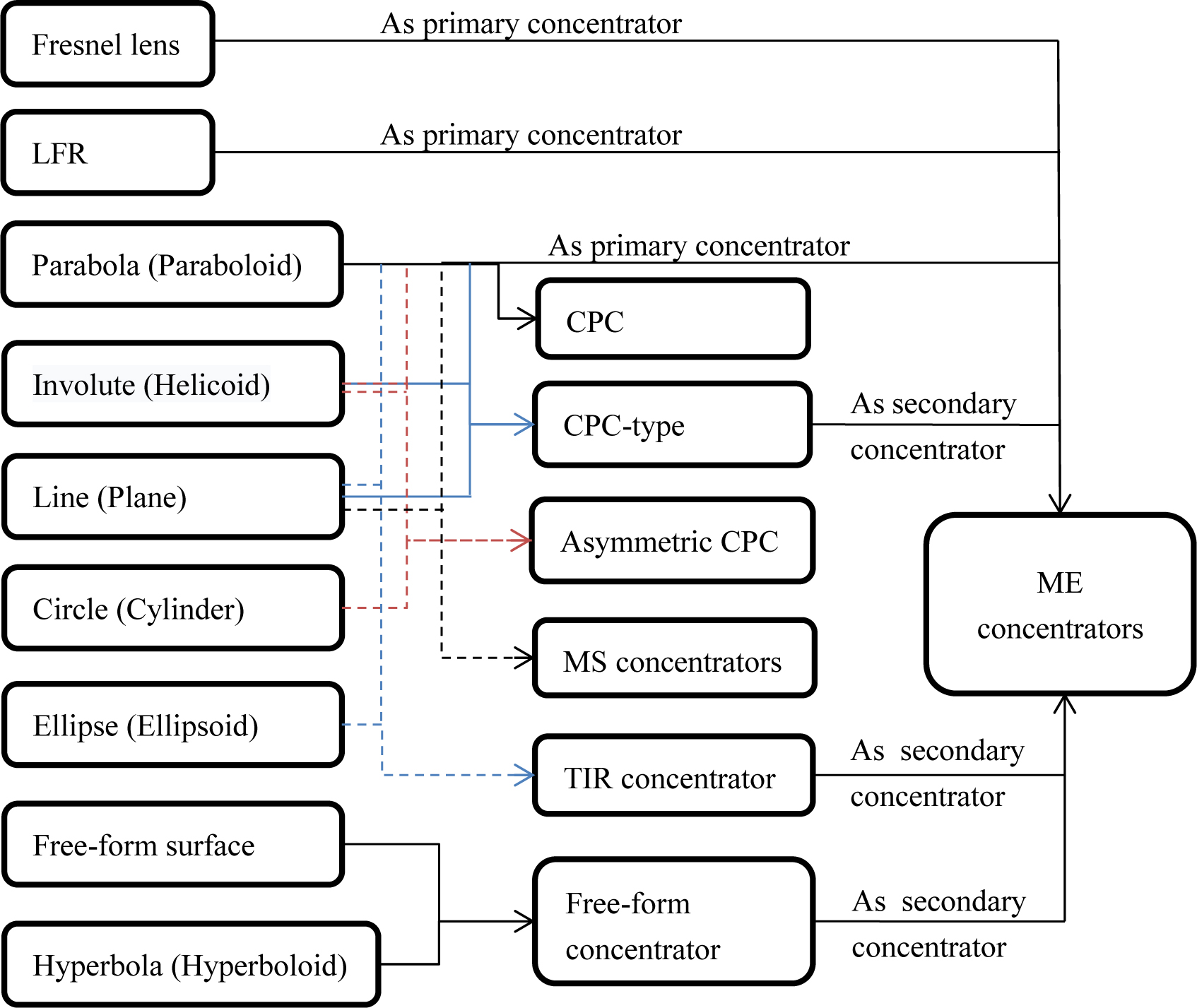
Fig. 28. Combination of MS and ME solar concentrators.
5.1.3. Research method
With the structures of solar concentrator becoming complicated, the research methods are also kept changing. Figure 29 shows the statistics on research methods in different periods. It could be found that before 1999, solar concentrators have been mainly researched by theoretical and experimental methods. Then between 2000 and 2009, the computer-aided method appeared and it was increasing greatly after 2010. Instead, the theoretical method is scarcely used. The reason is that computer technology was not popular before 1999, especially in optical application. The geometrical optics theory is the only method to study solar concentrator. Since 2000, the computer technolo gy was popularizing and computer-aided method such as numerical computation and optical simulation have been applied in optics. When after 2010, the various structures of solar concentrator and complex applications make it difficult to use theoretical method to make a multi-analysis. However, computer-aided method could easily deal with it. Monte-Carlo tracing theory that used in optical simulation software could simulate the characteristics of natural light. Moreover, the coupling property of energy conversion, transfer and dissipation could be obtained conveniently. Nevertheless, experiment is a generally used method. The computer-aided method could work out some results only under the ideal-defined boundary conditions, which are differ from the actual used conditions. Thus, experiment could verify the computer-aided work and even direct the process of computer-aided method reversely.
5.2. Discussion on universality
Figure 29
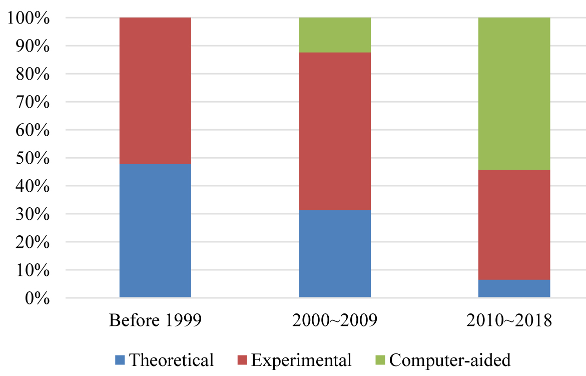
Fig. 29. Statistics on research methods in different periods.
Solar concentrator has been used for increasing the energy density and concentrating irradiance into a small area so that it could be collected expediently. With this understanding, a higher collection efficiency is being pursued. However, whatever MS or ME combination, the structure is more complex than a single surface or element concentrator. The costs of design, testing, manufacturing and the material consumption are increased unavoidably. Also, the optical efficiency would even reduce due to the processes increment of reflection and refraction. Why still did many researchers study on these complex concentrators? It could be found from references [20,21] that a parabolic and flat surfaces combined concentrator has more advantages than conventional CPC, such as low f-number, large acceptance angle, non-tracking as well as long working time. References [3,87,88] illustrate Fresnel lens could obtain a wider tracking error tolerance when employing a secondary concentrator. References [50-53,74] show that the large-size solar concentrator even cannot concentrate lights into the receiver entirely without adding the secondary concentrator. Therefore, in actual engineering application, the complexity on the structure of MS and ME combination concentrator is in exchange for several critical advantages, including increasing acceptance angle, improving collection efficiency, reducing the tracking precision and lower the cost of operation and maintenance etc.
5.3. Perspective
Solar energy is a widely distributed clean energy, which is also a future energy. Solar concentration is the most effective way to collect solar energy to obtain high quality energy. Solar concentrators with different GCRs could be applied to get energy with different qualities. The structure of solar concentrators go through from single to complex, the concentration performance has been improved concomitantly. Generally, enhancing usability of solar concentrator is the main direction of its development. Nowadays, solar applications are not limited in CT and CPV, but in many other fields such as solar daylighting, solar-pumped laser, solar cooling, solar desalination etc. It has been believed that more and more innovative designs on solar concentrator will be proposed in the future.
In addition, computer-aided analysis has greatly promoted the study of solar concentrator. The computer-aided design, numerical computation and simulation method have taking the place of conventional researching methods gradually. Computer-aided analysis will play an important role in future study on solar concentrator.
6. Conclusions
This paper reviewed the development of solar concentrators with MS and ME combinations. The combination on optical elements of MS and ME solar concentrators was diagramed and theirs advantages and disadvantages were evaluated. Concomitantly, the research method are also changed. Several conclusions have been summarized as follows:
- MS solar concentrators are usually designed for low power concentration. The acceptance angle is in the range of 30~60°, which is large enough to work with no tracking. ME solar concentrators are concerned more about high power concentration, so they have been designed with large sizes and GCR generally. The added assistant concentrators could greatly reduce the requirement on precision of tracking mechanism.
- Concentrators that used for CT pays more attention to lights’ intercepting ability, so involute surface is much more appropriated to the near-receiver part. However, involute surface is not suitable for CPV because it cannot ensure the light uniformity.
- The computer-aided method including numerical computation, optical simulation, etc. are gradually taking the place of conventional theoretical method, which makes it much easier to analyze various structures of solar concentrator and complex applications.
Acknowledgements
This work has been supported by the National High Technology Research and Development Program “863” of China (No. 2013AA102407-2, 2014).
Contributions
X. Ma conceived and wrote the article, H. Zheng helped categorize and summarize the references. S. Liu helped define the scope of this article and propose the prospective of the study. Also, H. Zheng and S. Liu helped check the viewpoints and language to make sure the article has high quality assurance.
References
- H. Price , E. Lu¨pfert , D. Kearney , E. Zarza , G. Cohen , R. Gee, R. Mahoney, Advances in parabolic trough solar power technology, Journal of Solar Energy Engineering 124 (2002) 109-125. https://doi.org/10.1115/1.1467922
- Q. Zou, Z. Li, H. Wu, R. Kuang, Y. Hui, Wind pressure distribution on trough concentrator and fluctuating wind pressure characteristics, Solar Energy 120 (2015) 464-478. https://doi.org/10.1016/j.solener.2015.02.014
- H. Zheng, C. Feng, Y. Su, J. Dai, X. Ma, Design and experimental analysis of a cylindrical compound Fresnel solar concentrator, Solar Energy 107 (2014) 26-37. https://doi.org/10.1016/j.solener.2014.05.010
- M. C. Robert, The Linear Fresnel lens Solar Concentrator: Transverse tracking error effects, National Aeronautics and Space Administration on Washington D.C, 1977.
- O. E. Miller, J. H. Mcleod, W. T. Sherwood, Thin sheet plastic Fresnel lenses of high aperture, Journal of the Optical Society of America 41 (11) 807-15. https://doi.org/10.1364/josa.41.000807
- M. Collares-Pereira, A. Rabl, R. Winston, Lens-mirror combinations with maximal concentration, Applied Optics 16 (10) 2677-2683. https://doi.org/10.1364/ao.16.002677
- W. T. Xie, Y. J. Dai, R. Z. Wan, K. Sumathy, Concentrated solar energy applications using Fresnel lenses: A review, Renewable and Sustainable Energy Reviews 15 (2011) 2588-2606. https://doi.org/10.1016/j.rser.2011.03.031
- D. C. Miller and S. R. Kurtz, Durability of Fresnel lenses: A review specific to the concentrating photovoltaic application, Solar Energy Materials & Solar Cells 95 (2011) 2037-2068. https://doi.org/10.1016%2Fj.solmat.2011.01.031
- J. Xiao, X. Wei, Z., W. Yu, Hongsheng Wu, A review of available methods for surface shape measurement of solar concentrator in solar thermal power applications, Renewable and Sustainable Energy Reviews 16 (2012) 2539-2544. https://doi.org/10.1016/j.rser.2012.01.063
- A. Mojiri, R. Taylor, E. Thomsen, G. Rosengarten, Spectral beam splitting for efficient conversion of solar energy—A review, Renewable and Sustainable Energy Reviews 28 (2013) 654-663. https://doi.org/10.1016/j.rser.2013.08.026
- D. A. Baharoon, H. A. Rahman, W. Zaidi, W. Omar, S. O. Fadhl, Historical development of concentrating solar power technologies to generate clean electricity efficiently—A review, Renewable and Sustainable Energy Reviews 41 (2015) 996-1027. https://doi.org/10.1016/j.rser.2014.09.008
- S. Madala, R. F. Boehm, A review of non-imaging solar concentrators for stationary and passive tracking applications, Renewable and Sustainable Energy Reviews 71(2017) 309-322. https://doi.org/10.1016/j.rser.2016.12.058
- M. Tian, Y. Su, H. Zheng, G. Pei, G. Li, and S. Riffat, A review on the recent research progress in the compound parabolic concentrator (CPC) for solar energy applications, Renewable and Sustainable Energy Reviews 82 (2018) 1272-1296. https://doi.org/10.1016%2Fj.rser.2017.09.050
- R. Winston, H. Hinterberger, Principles of cylindrical concentrators for solar energy, Solar Energy 17 (1975) 255-258. https://doi.org/10.1016/0038-092x(75)90007-9
- A. Rabl, Optical and thermal properties of compound parabolic concentrators, Solar Energy 6 (1976) 497-511. https://doi.org/10.1016/0038-092x(76)90069-4
- H. P. Baum, J. M. Gordon, Geometric characteristics of ideal nonimaging (CPC) solar collectors with cylindrical absorber, Solar Energy 33 (1984) 455-458. https://doi.org/10.1016/0038-092x(84)90198-1
- R. Winston, Principles of solar concentrators of a novel design, Solar Energy 16 (1974) 89-94. https://doi.org/10.1016/0038-092x(74)90004-8
- J. M. Gordon, M. Lasken, and H. Ries, Upper bounds for the yearly energy delivery of stationary solar concentrators and the implications for Concentrator optical design, Solar Energy 58 (1996) 197-202. https://doi.org/10.1016%2Fs0038-092x%2896%2900078-3
- M. Brogren, P. Nostell, B. Karlsson, Optical efficiency of a PV-thermal hybrid CPC module for high latitudes, Solar Energy 69 (2000) 173-185. https://doi.org/10.1016/s0038-092x(01)00066-4
- Y. Yu, N. Liu, G. Li, R. Tang, Performance comparison of CPCs with and without exit angle restriction for concentrating radiation on solar cells, Applied Energy 155 (2015) 284-293. https://doi.org/10.1016/j.apenergy.2015.06.012
- Y. Yu, R. Tang, Diffuse reflections within CPCs and its effect on energy collection, Solar Energy 120 (2015) 44-54. https://doi.org/10.1016/j.solener.2015.07.016
- W. Zheng, L. Yang, H. Zhang, S. You, and C. Zhu, Numerical and experimental investigation on a new type of compound parabolic concentrator solar collector, Energy Conversion and Management 129 (2016) 11-22. https://doi.org/10.1016%2Fj.enconman.2016.10.013
- J. Dai, H. Zheng, Y. Su, Z Chang, Reflector System Combined Three-Movement The Motional Design and Analysis for Linear Fresnel, Energy Procedia 14 (2012) 971-976. https://doi.org/10.1016/j.egypro.2011.12.1041
- R. Oommen, S. Jayaraman, Development and performance analysis of compound parabolic solar concentrators with reduced gap losses-oversized reflector, Energy Conversion and Management 42 (2001) 1379-1399. https://doi.org/10.1016/s0196-8904(00)00113-8
- R. Oommen, S. Jayaraman. Development and performance analysis of compound parabolic solar concentrators with reduced gap losses-‘V’ groove reflector, Renewable Energy 27 (2002) 259-275. https://doi.org/10.1016/s0960-1481(01)00185-9
- D. R. Mills, J. E. Giutronich, Asymmetrical non-imaging cylindrical solar concentrators, Solar Energy 20 (1978) 45-55. https://doi.org/10.1016/0038-092x(78)90140-8
- M. Bojic, N. Marjanovic, I. Miletic, L. Bojic, Comparison of optical performances of sea-shell trough solar concentrators, Energy and Buildings 98 (2015) 144-150. https://doi.org/10.1016/j.enbuild.2014.08.037
- X. Ning, R. Winston, and J. O’Gallagher, Dielectric totally internally reflecting concentrators, Apllied Optics 26 (1987) 300-305. https://doi.org/10.1364%2Fao.26.000300
- X. Yu, Y. Su, H. Zheng, S. Riffat, A study on use of miniature dielectric compound parabolic concentrator (dCPC) for daylighting control application, Building and Environment 74 (2014) 75-85. https://doi.org/10.1016/j.buildenv.2013.12.008
- C. Feng, H. Zheng, R. Wang, X. Yu, Y. Su, A novel solar multifunctional PV/T/D system for green building roofs, Energy Conversion and Management 93 (2015) 63-71. https://doi.org/10.1016/j.enconman.2015.01.001
- O. H. Cruz-Silva, O. A. Jaramillo, B. Monica, Full analytical formulation for Dielectric Totally Internally Reflecting Concentrators designs and solar applications, Renewable Energy 101 (2017) 804-815. https://doi.org/10.1016/j.renene.2016.09.037
- F. Mark, Solar Power and Concentration, Available at: https://www.e-education.psu.edu/eme812/node/7.
- H. P. Baum, M. E. Blanco, E. Gomez-Leal, J. M. Gordon, Optimal configurations of asymmetric CPC solar collectors with planar receivers, Solar Energy 36 (1986) 187-189. https://doi.org/10.1016/0038-092x(86)90125-8
- Y. Tripanagnostopoulos, P. Yianoulis, S. Papaeflhimiou, M. Souliotis, T. Nousia, Cost effective asymmetric CPC solar collectors, Renewable Energy 16 (1999) 628-631. https://doi.org/10.1016/s0960-1481(98)00239-0
- Y. Tripanagnostopoulos, M. Souliotis, Integrated collector storage solar systems with asymmetric CPC reflectors, Renewable Energy 29 (2004) 223-248. https://doi.org/10.1016/s0960-1481(03)00195-2
- M. Souliotis, P. Quinlan, M. Smyth, Y. Tripanagnostopoulos, A. Zacharopoulos, M. Ramirez, P. Yianoulis, Heat retaining integrated collector storage solar water heater with asymmetric CPC reflector, Solar Energy 85 (2011) 2474-2487. https://doi.org/10.1016/j.solener.2011.07.005
- H. Kessentini, N. C. Bouden, Numerical and experimental study of an integrated solar collector with CPC reflectors, Renewable Energy 57 (2013) 577-586. https://doi.org/10.1016/j.renene.2013.02.015
- K. He, H. Zheng, Y. Liu, Z. Chen, An imaging compounding parabolic concentrator, in: Proceeding of ISES solar world congress 2007 589-592. https://doi.org/10.1007/978-3-540-75997-3_108
- H, Kaiyan, Z. Hongfei, T. Tao, X. Xiaodi, Experimental investigation of high temperature congregating energy solar stove with sun light funnel, Energy Conversion and Management 50 (2009) 3051-3055. https://doi.org/10.1016/j.enconman.2009.08.009
- X. Xiaodi, Z. Hongfei, H. Kaiyan, C. Zhili, T. Tao, X. Guo, Experimental study on a new solar boiling water system with holistic track solar funnel concentrator, Energy 35 (2010) 692-697. https://doi.org/10.1016/j.energy.2009.10.033
- H. Zheng, G. Wu, T. Tao, Y. Su, and J. Dai, Combination of a light funnel concentrator with a deflector for orientated sunlight transmission, Energy Conversion and Management 88 (2014) 785-793. https://doi.org/10.1016%2Fj.enconman.2014.09.004
- T. Tao, Z. Hongfei, H. Kaiyan, A. Mayere, A new trough solar concentrator and its performance analysis, Solar Energy 85 (2011) 198-207. https://doi.org/10.1016/j.solener.2010.08.017
- H. Zheng, T. Tao, M. Ma, H. Kang, and Y. Su, Experimental test of a novel multi-surface trough solar concentrator for air heating, Energy Conversion and Management 63 (2012) 123-129. https://doi.org/10.1016%2Fj.enconman.2012.01.034
- M. Natarajan, T. Srinivas, Experimental and simulation studies on a novel gravity based passive tracking system for a linear solar concentrating collector, Renewable Energy 105 (2017) 312-323. https://doi.org/10.1016%2Fj.renene.2016.12.060
- C. Tíba, N. Fraidenraich,, Optical and thermal optimization of stationary non-evacuated CPC solar concentrator with fully illuminated wedge receivers, Renewable Energy 36 (2011) 2547-2553. https://doi.org/10.1016/j.renene.2011.02.007
- J. Chaves, M. Collares-Pereira, Ultra flat ideal concentrators of high concentration, Solar Energy 69 (2000) 269-281. https://doi.org/10.1016/S0038-092X(00)00106-7
- A. Timinger, W. Spirkl, A. Kribus, H. Ries, Optimized secondary concentrators for a partitioned central receiver system, Solar Energy, 69 (2000) 153-162. https://doi.org/10.1016/s0038-092x(00)00047-5
- C.-Y. Tsai, Enhanced irradiance distribution on solar cell using optimized variable-focus-parabolic concentrator, Optics Communications 305 (2013) 221-227. https://doi.org/10.1016/j.optcom.2013.04.052
- L. J. Richter, Optics of a two-trough solar concentrator, Solar Energy 56 (1996) 191-198. https://doi.org/10.1016/0038-092x(95)00091-5
- D. R. Mills, G. L. Morrison, Compact linear Fresnel reflector solar thermal power plants, Solar Energy 68 (2000) 263-83. https://doi.org/10.1016/s0038-092x(99)00068-7
- S. A. Omera, D. G. Infield, Design and thermal analysis of a two stage solar concentrator for combined heat and thermoelectric power generation, Energy Conversion & Management, 41 (2000) 737-756. https://doi.org/10.1016/s0196-8904(99)00134-x
- S. A. Kalogirou, Solar thermal collectors applications, Progress in Energy and Combustion Science 30 (2004) 231-295. https://doi.org/10.1016/j.pecs.2004.02.001
- J. Zhu and H. Huang, Design and thermal performances of Semi-Parabolic Linear Fresnel Reflector solar concentration collector, Energy Conversion and Management, 77 (2014) 733-737. https://doi.org/10.1016%2Fj.enconman.2013.10.015
- J. M. Gordon, D. Feuermann, P. Young, Unfolded aplanats for high-concentration photovoltaics, Optics Letters 33 (2008) 1114-1116. https://doi.org/10.1364/ol.33.001114
- X. Meng, X. Xia, C. Sun, and G. Dai, Optimal design of symmetrical two-stage flat reflected concentrator, Solar Energy 93 (2013) 334-344. https://doi.org/10.1016%2Fj.solener.2013.04.020
- Q. Cheng, J. Chai, Z. Zhou, J. Song, and Y. Su, Tailored non-imaging secondary reflectors designed for solar concentration systems, Solar Energy 110 (2014) 160-167. https://doi.org/10.1016%2Fj.solener.2014.09.013
- X. Meng, X. Xia, C. Sun, Y. Li, and X. Li, A novel free-form Cassegrain concentrator for PV/T combining utilization, Solar Energy 135 (2016) 864-873. https://doi.org/10.1016/j.solener.2016.06.034
- B.-H. Lim, K.-K. Chong, C.-S. Lim, and A.-C. Lai, Latitude-orientated mode of non-imaging focusing heliostat using spinning-elevation tracking method, Solar Energy 135 (2016) 253-264. https://doi.org/10.1016%2Fj.solener.2016.05.038
- K.K. Chong, Optical analysis for simplified astigmatic correction of non-imaging focusing heliostat, Solar Energy 84 (2010) 1356-1365. https://doi.org/10.1016/j.solener.2010.04.013
- K.K. Chong, C.Y. Lim, C.W. Hiew, Cost-effective solar furnace system using fixed geometry Non-Imaging Focusing Heliostat and secondary parabolic concentrator, Renewable Energy 36 (2011) 1595-1602. https://doi.org/10.1016/j.renene.2010.11.010
- C.-W. Wong and K.-K. Chong, Solar flux distribution study of non-imaging dish concentrator using linear array of triple-junction solar cells scanning technique, Solar Energy 125 (2016) 86-98. https://doi.org/10.1016/j.solener.2015.11.029
- K.-K. Chong, T.-K. Yew, C.-W. Wong, M.-H. Tan, W.-C. Tan, B.-H. Lim, Dense-array concentrator photovoltaic prototype using non-imaging dish concentrator and an array of cross compound parabolic concentrators, Applied Energy 204 (2017) 898-911. https://doi.org/10.1016/j.apenergy.2017.03.108
- T.-K. Yew, K.-K. Chong, and B.-H. Lim, Performance study of crossed compound parabolic concentrator as secondary optics in non-imaging dish concentrator for the application of dense-array concentrator photovoltaic system, Solar Energy 120 (2015) 296-309. https://doi.org/10.1016/j.solener.2015.07.026
- M. Abdelhamid, B. K. Widyolar, L. Jiang, R. Winston, E. Yablonovitch, G. Scranton, D. Cygan, H. Abbasi, and A. Kozlov, Novel double-stage high-concentrated solar hybrid photovoltaic/thermal (PV/T) collector with nonimaging optics and GaAs solar cells reflector, Applied Energy 182 (2016) 68-79. https://doi.org/10.1016/j.apenergy.2016.07.127
- B. K. Widyolar, M. Abdelhamid, L. Jiang, R. Winston, E. Yablonovitch, G. Scranton, D. Cygan, H. Abbasi, and A. Kozlov, Design, simulation and experimental characterization of a novel parabolic trough hybrid solar photovoltaic/thermal (PV/T) collector, Renewable Energy, 101(2017) 1379-1389. https://doi.org/10.1016/j.renene.2016.10.014
- S. Wang, J. Shi, H.-H. Chen, S. R. Schafer, M. Munir, G. Stecker, W. Pan, J.-J. Lee, C.-L. Chen, Cooling design and evaluation for photovoltaic cells within constrained space in a CPV/CSP hybrid solar system, Applied Thermal Engineering 110 (2017) 369-381. https://doi.org/10.1016/j.applthermaleng.2016.08.196
- A. E. Kabeel, M. Abdelgaied, Observational study of modified solar still coupled with oil serpentine loop from cylindrical parabolic concentrator and phase changing material under basin, Solar Energy 144 (2017) 71-78. https://doi.org/10.1016/j.solener.2017.01.007
- T. Arunkumar, D. Denkenberger, Amimul Ahsan, R. Jayaprakash, The augmentation of distillate yield by using concentrator coupled solar still with phase change material, Desalination 314 (2013) 189-192. https://doi.org/10.1016/j.desal.2013.01.018
- M. Pereira, A. Rabl, R. Winston, Lens-mirror combinations with maximal concentration, pplied Optics 16 (1977) 2677. https://doi.org/10.1364/ao.16.002677
- D. T. Nelson, D. L. Evans, R. K. Bansal, Linear Fresnel lens concentrators, Solar Energy 17 (1975) 285-289. https://doi.org/10.1016/0038-092x(75)90045-6
- Z. Hongfei, M. Xinglong, C. Jiaxiang, An investigation on a solar collecting system with cylindrical Fresnel lens, Journal of Engineering Thermophysics 11 (37) 2277-2281.
- M. Burhan, S. J. Oh, K. J. E. Chua, and K. C. Ng, Solar to hydrogen: Compact and cost effective CPV field for rooftop operation and hydrogen production, Applied Energy 194 (2017) 255-266. https://doi.org/10.1016/j.apenergy.2016.11.062
- L. Fu, R. Leutz, and H. P. Annen, Secondary optics for Fresnel lens solar concentrators, Nonimaging Optics: Efficient Design for Illumination and Solar Concentration VII, edited by Roland Winston, Jeffrey M. Gordon, Proc. of SPIE Vol.9, 7785-7789. https://doi.org/10.1117/12.860438
- A. Cvetkovic, R. Mohedano, O. Gonzalezet al, Performance Modeling of Fresnel-Based CPV Systems: Effects of Deformations under Real Operation Conditions. 7th International Conference on Concentrating Photovoltaic Systems AIP Conf. Proc. 1407, 74-78 (2011).
- P. Zamora, P. Benítez, R. Mohedano Arroyo, A. Cvetkovic, J. F. Vilaplana, Y. Li, M. Hernández, J. C. Chaves, J. C. Miñano, Experimental characterization of Fresnel-Köhler concentrators, Journal of Photonics for Energy 2 (2012) 021806. https://doi.org/10.1117/1.jpe.2.021806
- R. Mohedano, A. Cvetkovi, P. Benítez et al. Progress In Fresnel-Köhler Concentrators. 7th International Conference on Concentrating Photovoltaic Systems AIP Conf. Proc. 1407, 270-273, 2011.
- P. Zamora, P. Benitez, Y. Li, J. C. Miñano, J. Mendes-Lopes, K. Araki, The Dome-Shaped Fresnel- Köhler concentrator, High and Low Concentrator Systems for Solar Electric Applications VII, edited by Kaitlyn VanSant, Adam P. Plesniak, Proc. of SPIE Vol. 8468, 84680D. https://doi.org/10.1063/1.4753836
- A. Goldstein, J. M. Gordon, Tailored solar optics for maximal optical tolerance and concentration, Solar Energy Materials and Solar Cells 95 (2011) 624-629. https://doi.org/10.1016/j.solmat.2010.09.029
- D. R. Mills, G. L. Morrison, Compact linear Fresnel reflector solar thermal powerplants, Solar Energy 68 (2000) 263-283. https://doi.org/10.1016/s0038-092x(99)00068-7
- A. E. Rungasamya, K. J. Craigb, J. P. Meyerc, 3-D CFD modeling of a slanted receiver in a compact linear Fresnel plant with etendue-matched mirror field, Energy Procedia 69 (2015) 188-197. https://doi.org/10.1016/j.egypro.2015.03.022
- M. Lando, J. Kagan, B. Linyekin, L. Sverdalov, G. Pecheny, and Y. Achiam, An astigmatic corrected target-aligned solar concentrator, Optics communication 180 (2000) 127-132. https://doi.org/10.1016/s0030-4018(00)00686-6
- K. He, H. Zheng, Z. Li, Taotao, and J. Dai, Design and investigation of a novel concentrator used in solar fiber lamp, Solar Energy 83 (2009) 2086-2091. https://doi.org/10.1016/j.solener.2009.08.006
- J. D. Muhs, Hybrid lighting doubles the efficiency and affordability of solar energy in commercial buildings, in: CADDET Energy Efficiency Newsletter, 2000, 6-9.
- J. D. Muhs, Design and analysis of hybrid solar lighting and full spectrum solar energy systems, in: Proceedings of the American Solar Energy Society SOLAR 2000 Conference, Madison. https://doi.org/10.2172/811437
- W. E. Horne, Conversion of solar to electrical energy, US Patent 4,313,024, 1982.
- M. Burhan, K. J. E. Chua, and K. C. Ng, Simulation and development of a multi-leg homogeniser concentrating assembly for concentrated photovoltaic (CPV) system with electrical rating analysis, Energy Conversion and Management 116 (2016) 58-71. https://doi.org/10.1016/j.enconman.2016.02.060
- X. Ma, H. Zheng, and Z. Chen, An investigation on a compound cylindrical solar concentrator (CCSC), Applied Thermal Engineering 120 (2017) 719-727. https://doi.org/10.1016/j.applthermaleng.2017.04.030
- C. Feng, H. Zheng, R. Wang, and X. Ma, Performance investigation of a concentrating photovoltaic/thermal system with transmissive Fresnel solar concentrator, Energy Conversion and Management 111 (2016) 401-408. https://doi.org/10.1016/j.enconman.2015.12.086
- D. E. Soule, Hybrid solar energy generating system, US Patent 4,700,013, 1987.
- A. Yogev, J. Appelbaum, M. Oron, N. Yehezkel, Concentrating and splitting of solar radiation for laser pumping and photovoltaic conversion, Journal of Propulsion Power 12 (1996) 405-409. https://doi.org/10.2514/3.24043
- A. Segal, M. Epstein, A. Yogev, Hybrid concentrated photovoltaic and thermal power conversion at different spectral bands, in: Proceedings of the ISES World Congress—Solar Energy for a Sustainable Future, Gothenburg, Sweden, 2003. https://doi.org/10.1016/j.solener.2003.12.002
- C.-Y. Tsai, Improved irradiance distribution on high concentration solar cell using free-form concentrator, Solar Energy 115 (2015) 694-707. https://doi.org/10.1016/j.solener.2015.03.032
- C.-Y. Tsai, Optimized solar thermal concentrator system based on free-form trough reflector, Solar Energy 125 (2016) 146-160. https://doi.org/10.1016/j.solener.2015.12.011
- K. Yoshioka, A. Suzuki, T. Saitoh, Performance evaluation of two-dimensional compound elliptic lens concentrators using a yearly distributed insolation model, Solar Energy Materials & Solar Cells 57 (1999) 9-19. https://doi.org/10.1016/s0927-0248(98)00161-5
- K. Ryu, J.-G. Rhee, K.-M. Park, and J. Kim, Concept and design of modular Fresnel lenses for concentration solar PV system, Solar Energy 80 (2006) 1580-1587. https://doi.org/10.1016/j.solener.2005.12.006
- M. D. Hughes, C. Maher, D. B. Tasciuc, D. Polanco, D. Kaminski, Performance comparison of wedge-shaped and planar luminescent solar concentrators, Renewable Energy 52 (2013) 266-272. https://doi.org/10.1016/j.renene.2012.10.034
- J. M. Kim and P. S. Dutta, Optical efficiency–concentration ratio trade-off for a flat panel photovoltaic system with diffuser type concentrator, Solar Energy Materials & Solar Cells 103 (2012) 35-40. https://doi.org/10.1016/j.solmat.2012.04.012
- C.-W. Liang and J.-S. Lin, High concentration thin profile solar concentrator utilizing toroidal confocal relay, Solar Energy 122 (2015) 264-270. https://doi.org/10.1016/j.solener.2015.08.030
Copyright © 2019 The Author(s). Published by solarlits.com.

911
Total views
Citations
SHARE ON


