Volume 10 Issue 1 pp. 87-98 • doi: 10.15627/jd.2023.7
Ray Tracing Algorithm to Simulate Laser-Cut Panel Light-Redirecting Elements
Pedro Vitor Sousa Ribeiro,⁎ Ricardo Carvalho Cabús
Author affiliations
Universidade Federal de Alagoas, Maceió, Brasil
*Corresponding author.
pedrovsribeiro@academico.ufs.br (P. V. S. Ribeiro)
r.cabus@gmail.com (R. C. Cabús)
History: Received 17 October 2022 | Revised 2 May 2023 | Accepted 7 May 2023 | Published online 28 June 2023
Copyright: © 2023 The Author(s). Published by solarlits.com. This is an open access article under the CC BY license (http://creativecommons.org/licenses/by/4.0/).
Citation: Pedro Vitor Sousa Ribeiro, Ricardo Carvalho Cabús, Ray Tracing Algorithm to Simulate Laser-Cut Panel Light-Redirecting Elements, Journal of Daylighting 10 (2023) 87-98. https://dx.doi.org/10.15627/jd.2023.7
Figures and tables
Abstract
Daylighting simulation software is an important tool to improve the quality of building design and to improve the quality of the built environment. For its application to correspond to reality, its algorithm needs to reflect real behaviour in the best possible way. This paper aims to propose an algorithm to simulate the behaviour of fenestration complex systems, such as the laser-cut panel, based on ray tracing techniques. The algorithm was developed in MatLab as an add-on for the TropLux software, using the physical formulas associated with the concepts of daylight coefficients, ray tracing and Monte Carlo method. After validation it is possible to realize that the developed algorithm can simulate the light behaviour through complex fenestration systems using plane-based modelling with precision and accuracy. The tests using laser cut panel, ordinary glass and prismatic glass obtained behaviour close to that observed in similar measurements and algorithms.
Keywords
Daylight, Laser-Cut panel, Software, Ray tracing
1. Introduction
Window is the basic interface between the internal and external environment in a building, and its definition must assume, in addition to the light input function, user and building parameters. Lam [1] points out that the perception of location, of the passage of time, of orientation and even of its psychological comfort influences the form and determination of the type of opening and the user's relationship with it.
The capture of daylight through the window shall be treated so as to cover the various effects its entry causes to the internal environment. Different opening positions result in different forms of light input and distribution, restricting its use and the strategies for protection and capture. There are several types of solar protection systems that are simple to apply and that brings great benefits to the internal environment, they are: the marquee, the light shelf, and the louvre. These elements seek above all to ensure that there is no direct sunlight entering the work plan and, where possible, redirecting the light into the environment to make the best use of it.
Faced with the limitations that traditional devices for capturing and controlling daylight impose, new elements arise that seek to overcome them using technology. Kazanasmaz and Ors [2] define advanced systems as those that apply technological advances in the field of materials and existing optical knowledge to develop elements capable of obstructing direct sunlight, avoiding glare and transporting daylight, in a reflected manner, to regions further away from the window.
1.1. The laser cutting panel (LCP)
LCP was developed by engineer Ian R. Edmonds in 1989 and patented in 1991 [3]. The element consists of an acrylic plate where parallel cuts are made with a laser cutter, fusing it into a highly reflective surface that generates the total internal reflection effect. The cuts can be angled or perpendicular to the surface [4]. Some applications also include cuts in semi-circular format and with uneven distributions [5].
Its application does not obstruct the external view, it can also be used at the user level, however it is usually positioned at the top of the window, at a proportion of 1/3 of the window height [6]. It can also be applied to mobile structures, allowing the adjustment of the angle of reflection [7]. Preliminary studies by Edmonds [4] point out that 90% of the light incident on the panel, for solar heights greater than 45°, is deflected towards the ceiling of the environment, 2% crosses the panel directly and 8% is deflected towards the ground, externally.
When incident on the panel, the light beam can be deflected by the cutting surface towards the interior of the environment with minimal losses, by the effect of total internal reflection, or it can cross the material in the same direction. When the cut is angled, the deflected rays inside will come out on the other side of the material at a different angle from the input, allowing the cut to be adjusted in order to obtain the greatest luminous gain [8]. The way the LCP interacts with light is related to parameters such as the inclination of the cut on the plates, the thickness of the material, the distance between the cuts and the refraction index of the material. The main characteristic that defines the panel is the relationship between the distance of the cuts and the thickness of the material (D/W) (Fig. 1).
Figure 1
![Behaviour of light beam when focusing on PCL [9].](figures/10-87-1.jpg)
Fig. 1. Behaviour of light beam when focusing on PCL [9].
Initial studies by Edmonds [4] show that the panel works best under clear sky conditions, positioned with the cuts horizontally, and at an angle of inclination corresponding to half the maximum solar height. Still, it indicates that there is a considerable reduction in the external view from the panel, of up to 50% when positioned at 60º. A formula for the application of the panel was proposed by Edmonds [4], regardless of the orientation, as presented in Eq. (1).
where E is the maximum solar elevation and θpanel is the angle of application of the element in the window in relation to the vertical, with the axis at the top.
For regions of urban canyons, the author suggests that the panel must be applied at 30º vertically. Laar [9], when comparing LCP with plexiglass, explains that the gain in illuminance with LCP exceeds that of the other material. Ciampini [8] analysed the material using scale models and real sky for several advanced systems in daylighting. The author concludes that the channel panel obtained the best results, promoting a homogeneous luminance distribution, generating low levels of contrast on the surfaces illuminated by the deflected rays. The results of Ciampini [8] were confirmed by Santos [10] and Kadir et al. [11] for subtropical skies. Studies in real environments, such as the one conducted by Labib [12] pointed out that the LCP system proved to have a simple application, that resulted in significant gains, regarding the case of the study, in classrooms, mainly in clear and partially covered sky conditions.
Besides its isolated application, it is possible to use the LCP combined with other elements to increase the efficiency of the system. Obradovic and Matusiak [13] observed that the application of LCP as a collector on light pipe can significantly increase the entry of natural light, both in clear and overcast conditions. The results can be observed in Singh, Bisht and Garg [14] research, with some advances like development of panels with oriented cuts and with different depths. Davila e Fiorito [15] also observed that the use of LCP combined with a horizontal blind reduces the risk of discomfort glare of the occupants. Secondly when combined with Fresnel collectors, as showed by Nair, Ganesan and Ramamurthy [16]. The authors affirmed that the use of grades LCP perform better with Fresnel collectors than the other LCP types, and that better performance was observed with LCP in comparison with acrylic dome.
2. Computational simulation of complex fenestration systems
For the performance of an advanced device in daylighting to be evaluated, the computational tool must be able to simulate the optical characteristics of the material in question. Some basic features such as reflectance and transmittance of materials are easily inserted into all simulation software, however only a few allow to go beyond that. The refraction of light beam is usually not properly computed in simplified tools, regarding its little influence on the luminous performance of common glass environments.
Software that wishes to simulate the characteristics of a given translucent material must incorporate into its algorithm tools that allow it to deal with the optical phenomena of light. Daylighting simulation programs that work with the radiosity method usually characterize the complex fenestration systems using The Bidirectional Transmission (or Reflection) Distribution Function, abbreviated BT(R)DF [17], which is synthesized in the BSDF (bidirectional scattering distribution function) [18]. In simplified form, this function relates the incident light in a plane with the distributions, in spherical coordinates, of the reflected and transmitted quantities, simplifying the internal complexity of certain elements, such as the LCP. In software where the ray tracing method is used, the treatment of light rays within complex systems can be studied in a broader way, evaluating their behaviour within the materials. Some materials already have formulations to be treated in such software, like the common glass [19] and the prismatic glasses [20], however the LCP still lacks studies.
The present aims to propose an algorithm for the simulation of daylight redirection elements of the laser cut panel type based on ray tracing techniques. The developed algorithm is not limited to LCP, but allows dealing with any translucent material, provided that its geometry can be computationally modelled.
4. Mathematical model
Two aspects define the optical characteristics of materials, reflectance, and transmittance, in specular and diffuse forms. In addition, the component absorbed by the material is added. When the radiation falls on a surface, one portion is absorbed by the material, one is reflected, and the rest is transmitted through the body in a way that each added energy portion results in the initial amount [21].
Refraction is another phenomenon observed in the environments where light falls. The change in the angle of the ray of light, when passing from one medium to another, happens due to different speed of light propagation in the materials. This particular aspect, depending on the angle of incidence of the light beam and the shape of the element, can cause the effect of chromatic dispersion, which is the division of the original light beam into different wavelengths in the visible colour spectrum [22].
The effect of changing the direction of a light beam when crossing an interface between two media is defined by Snell's law. Refraction is defined when a light beam reaches the interface between two non-dielectric materials: it tends to change speed, and thus move away from or towards normal, depending on the refractive index of the materials. After impacting the medium, the electromagnetic wave may reflect on the surface, be transmitted by the medium or be absorbed, or the combination of effects [23]. The relationship between the angle of incidence θi) and the angle of transmission of the ray after the interface (θt) is given by the Snell’s law, presented in Eq. (2) [24].
where n1 indicates the index of refraction of the material 1 and n2 the index of refraction of the material 2.
For refractive index that are the same in both media, the ray of light does not change its trajectory, but as one of the indexes changes the ray tends to approach or depart from the normal vector of the incidence plane. In the situation where the refractive index of the medium originating in the ray is higher than the medium in which it must cross, a trend away from the normal of the interface plane is observed. There is an incidence angle where the transmission angle passes 90º, resulting in the effect called total internal reflection [25].
It is important to point out that as the area where the effect of total internal reflection takes place is the interface between two planes, and that its thickness is insignificant, the effect of absorption is negligible, but only in regard to the integral reflection of the incident light beam [22]. This effect is very important because it will be the basis for the operation of the LCP among other elements such as fibre optics.
In a normal incidence to the plane the transmission of the light beam is total, but while this angle increases there is a decrease in the transmitted component and an increase in the reflected component. Some formulations of the wave allow to calculate the reflectance for the two polarities of the light wave, these laws determine the reflected fraction as well as the transmitted fraction and are called Fresnel coefficients [22]. Eqs. (3) and (4) define the behaviour for perpendicular and parallel polarities.
where and are the reflections of the planes in which lightning strikes the electromagnetic wave perpendicular and parallel, respectively, to the plane containing the lightning , θi e θt are the angles of incidence and transmission of the light beam respectively in relation to the normal of the incident plane, and ni e nt are the indexes of refraction of the medium containing the incident ray and transmitted, respectively.
The two polarizations of the light wave can be better understood in Fig. 2, in which the previously presented formulations are based.
Figure 2
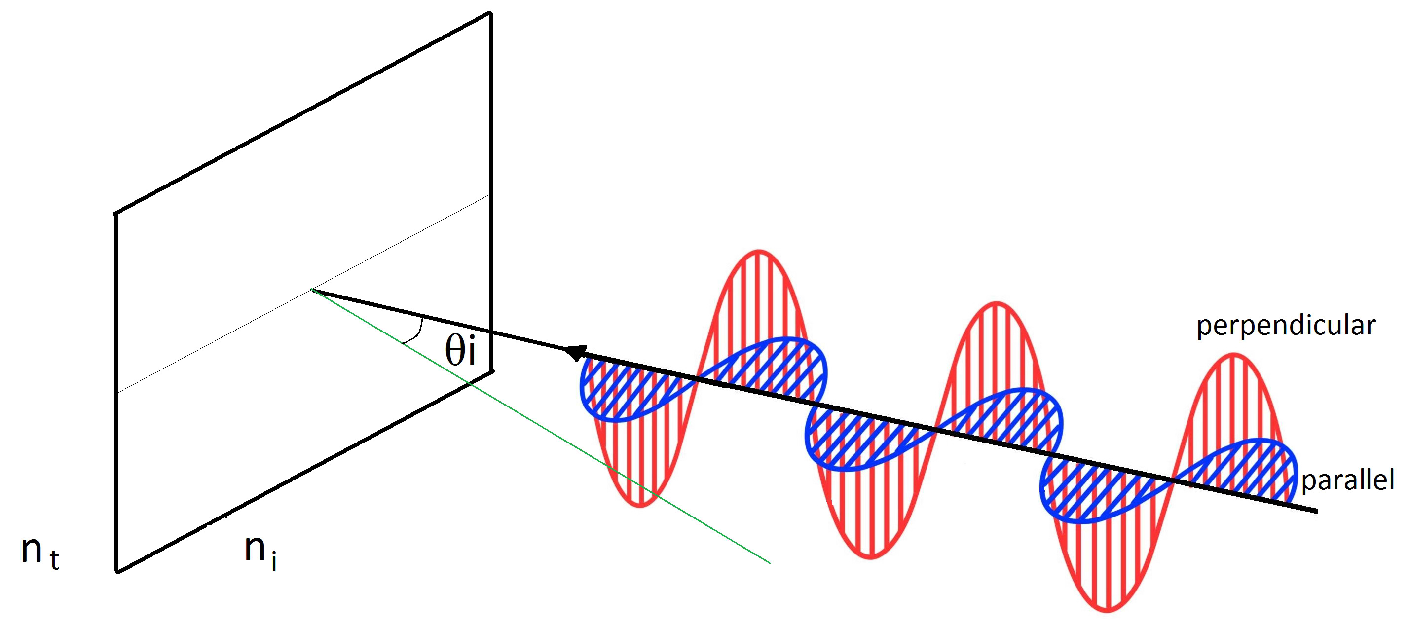
Fig. 2. Polarisation of the incident light wave in a plane.
According to Stamnes [23], daylight can be treated as a non-polarized light, in view of the constant variability of its polarisation. In view of this it is possible to define the plots reflected and transmitted by equations 5 and 6.
In which R is the reflectance of the interface between the media for the given angle of incidence, and by the fact that in the reflection in interfaces there is no absorption of light, the transmittance is what is left to complete 100% of the light energy of the ray. In order for such a formula to be used in the calculation of reflectance it is necessary to know the angles of incidence and transmission of the light beam. The calculation is performed when the light beam reaches a plane of the model, and its transmission angle is not yet known. For this it is necessary to calculate it using Snell's law, presented in Eq. (1), combined with the law of trigonometry presented in Eq. (7).
It turns out Eq. (8):
By replacing Eq. (8) in Eqs. (3) and (4), a formula is obtained that has as its parameters only the refractive index of the media and the angle of incidence of the light beam, as presented in Eqs. (9) and (10), and is possible to be implemented in the algorithm.
Based on the formulas for the directional characteristics, it is also necessary to calculate the angle of refraction of the light beam for each angle of incidence. By Glassner [24], the relationship between the angle of the incident radius and the refractory ray is given in Eq. 11.
where vr is the refracted vector, r is the ni/nt, l is the incident vector, and n is the normal vector to the plane.
Using Snell's law presented in Eq. (2), in order to eliminate the variable angle of the transmitted radius from the equation, the formula presented in Eq. (12) is obtained. By its use is possible to obtain the refractory vector, in terms of its direction cosines.
For the reflected vector, where the angle of reflection is equal to the angle of incidence, the formula given by Greve [26] is used, where the relationship between the angle of the incident radius and the reflected one is presented in Eq. (12).
where, by the notation used, is the reflected ray, i=L’ is the incident ray, and n=n’ is the normal vector to the plane.
where,
The use of a simulation software in daylighting is an option for evaluating the performance of an advanced lighting device, however the program should have in its base formula the requirements to work with optical events such as total internal reflection. That software commonly uses simplified equations to deal with reflection and transmission effects, and the refractive effects of the light beam are usually not properly computed in view of their small influence on the luminous performance of common glass environments. For advanced elements it is common that equations are limited to the specific case of each type of element, as is the case of Edmonds et al. [27] for LCP and Mashaly et al. [28] for prismatic glasses.
Tregenza and Sharples [19] present a formula for directional transmittance in transparent glasses with parallel faces, the common glass, which is commonly used by the simulation software in daylighting, like a TropLux [29,30]. The formula is as shown below,
where ti is the directional transmission and i is the angle of incidence of the light beam relative to the normal of the plane.
Edmonds et al. [19] developed an algorithm that allows the simulation of LCP in Radiance software, using the prismatic elements module that the software provides. For this it was necessary that the author described physically the behaviour of the light beam inside the material. The first step was to calculate directional reflectance; therefore, they propose the following formula presented in Eqs. (16)-(20)
where \(\dot{R}\) is the cosine between ray and surface normall, rte is the reflectance in parallel polarity, rtm is the rteflectance in perpendicular polarity, A2 is the index of refraction of the medium, R is the directional reflectance of incident beam, and T is the directional transmission of the incident beam.
If we compare the results obtained using the formula presented by Tregenza and Sharples [19] with that of the Fresnel coefficients and with that of Edmonds et al [27] the results obtained by the formula of Tregenza and Sharples [19] have a different behaviour from the other models, mainly those taken as reference, which uses the Fresnel coefficients presented by Hetch [22]. The behaviour of the model of Edmonds et al. [27] showed minor differences, remaining far from the basic theoretical model.
This difference shows that the adoption of the Edmonds [4] models, or of Tregenza, and Sharples [19], in the LCP simulation may result in considerable differences. The first, from Edmonds, still brings with it the rest of the algorithm where the reflected fractions are defined, transmitted directly and in a refracted way by the panel using the formula presented, however its application to ray tracing becomes complicated in consideration of the logic used by the "prism2" module of Radiance, on which the algorithm is based, by combining the methods of calculation of Ray Tracing and radiosity. The model presented by Tregenza and Sharples [19] is limited to the application of glass elements with parallel faces, and without the total internal reflection effect found in the LCP panel and other advanced devices, making its use impossible in such situations, as Lowry and Thomas [31] also states. The disputes substantiate the choice of using the Fresnel’s coefficients presented by Hecht [22] in the algorithm developed in TropLux.
The choice is also based on the studies developed by Andersen et al. [32], who studied whether the simulation of prismatic elements using Monte Carlo methods combined with Ray Tracing results in behaviour similar to that measured in real models using BTDF [33]. The studies revealed that the combination of Monte Carlo method with Ray Tracing, associated with Snell-Descartes concepts and Fresnel's law, achieved results very similar to those acquired by the real model, but in models with complex plan geometry the operational cost can be high.
4. Methodology
The developed algorithm was implemented with an add-on in the daylighting simulation software TropLux [30], developed by Cabús [29]. This is based on the ray tracing method combined with daylight coefficients [27] and the Monte Carlo method applied to daylighting [35]. TropLux software is validated [36] and has been widely used in scientific papers such as national [37] and international [38] thesis, dissertations [39], articles in national [40] and international [41] congresses, and in national [42] and international [43] journals. Its code was developed in Matlab® and the computational model inserted in the program is based on a geometry formed by rectangular planes defined by the coordinates of their vertices, where characteristics such as reflectance and transmittance are defined. The combination of several planes allows the creation of complex geometries.
To validate the new functions, it is necessary to check the directional transmittance and reflectance characteristics obtained in the algorithm for different advanced elements and compare them with other results already found in the literature. The photometric behaviour of the materials was checked for transmittance and directional reflectance. For this purpose, the behaviour of three elements were compared: ordinary glass, prismatic glass type 45/45 and laser cut panel with D/W ratio of 0.3. The procedure consists of emitting a light beam on the element in the computational model and checking the number of rays transmitted and reflected to the outside and deflected. The benchmarks used in the comparisons for each type of material are described in Table 1.
Table 1
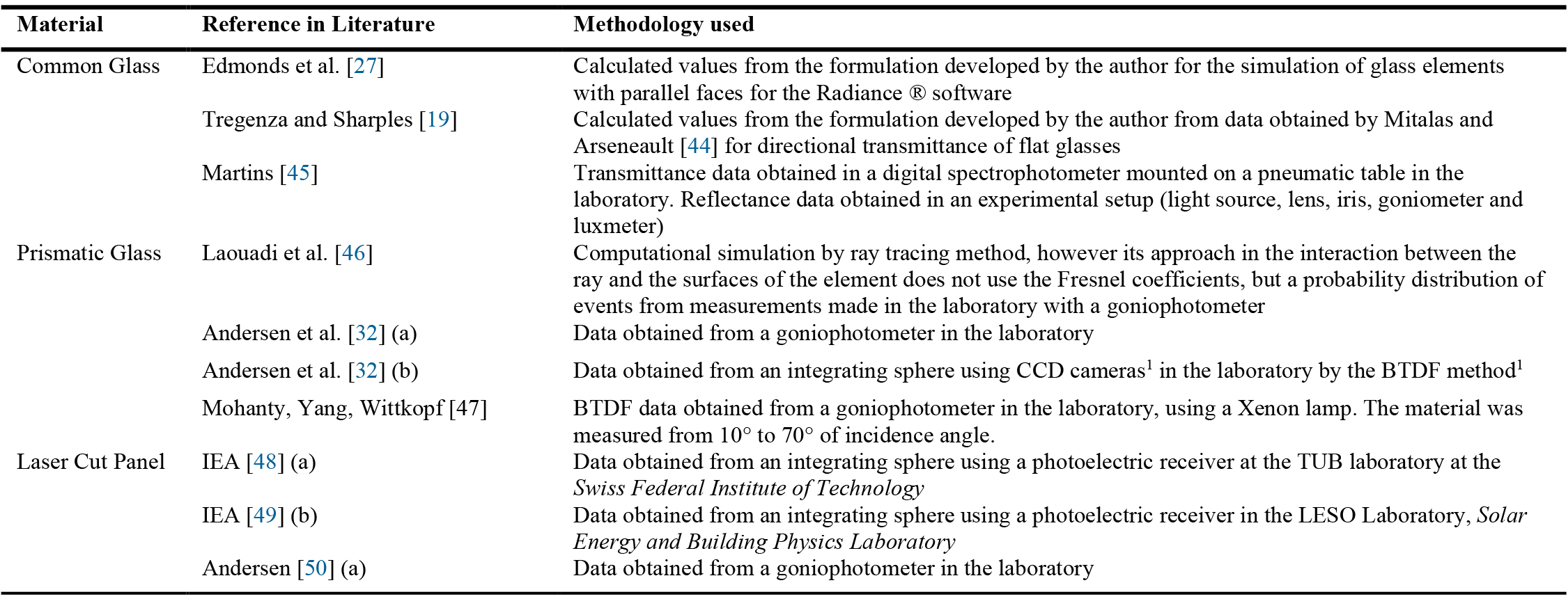
Table 1. Theoretical references used in comparisons for algorithm validation.
1 CCD - charge-coupled device: is a semiconductor imaging sensor formed by an integrated circuit containing an array of coupled capacitors.
2 BTDF - bidirectional scattering distribution function: Set of mathematical functions that describe the behaviour of a light beam focusing on a surface from a probability distribution of events.
The results were presented in a radial diagram where transmittance and reflectance for each angle of light incidence are presented. The data was also compared in a linear regression to check the correspondence between the values in the literature and those obtained by the model.
Finally, the portion of light deflected by the laser cutting panel was analysed. Edmonds [4], using measurements under the condition of a real covered sky, was able to calculate the percentage of light transmitted by the element that was deflected, making the results available to be compared with those of the developed algorithm.
5. Results
Based on the algorithm used by TropLux, auxiliary routines were developed to allow the software to work with light transmission between media with different densities. The methodology of the TropLux algorithm - including ray tracing, Monte Carlo and daylight coefficients are used - is described in the thesis of Cabús [29] and was fundamental for the development of the algorithm.
When working with different media, they are usually associated with the idea of volume, however, when dealing with light only the interface surface between them maters, as the media will be treated by the plans that compose their domain. Computationally, in TropLux, the plan is defined by four points, in which the face to which it is facing is defined by the order in which the points are described. This feature requires two sides, one facing each side, to correctly define an actual plan.
In this way, each two-sided plane will correspond to the interface between two media. In Fig. 3, it is possible to observe how the light beam behaves using this new setting configuration. The light beam from N2 reaches the prismatic element in one of its planes composed of two faces, one facing inwards in blue and the other outward in red. At the point of impact, the ray identifies the plane reached as well as the corresponding face and computes a refractive index change from N2 to N1, changing its direction. Within the prism, the ray reaches the opposite plane, on a face that indicates a new change, now from an index of refraction N1 to N2. From this route, you can define two types of faces, in which the order of the refractive index is different, and which will be used in the new algorithm.
Figure 3
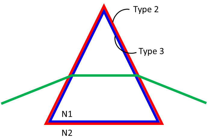
Fig. 3. Schematization of the behaviour of the ray of light when interacting with a prismatic element.
In this sense, the means are defined by the faces facing in and out of them, as well as the refractive indexes for each material. This system allows numerous different types of materials to be added in the same model.
5.1. Data processing
The processing of illuminance in TropLux is performed in three distinct steps: the calculation of direct and diffuse daylight coefficients and the calculation of illuminance. The algorithm was inserted in the first two processing steps, when the program calculates the direct and diffuse daylight coefficients for the simulation point requested by the user.
In the processing of the direct coefficients, TropLux launches rays from the point of analysis directly to the centre of the sky sectors used. Cabús [29] uses as basis the sky division of 145 sectors proposed by CIE [51], however, considering that the area that the sun occupies in the sky is much smaller than the area of an original sector, a more refined division of 5221 parts is used in TropLux. The process of calculating the direct daylight coefficients is presented in Fig. 4.
Figure 4
![Flowchart for processing the direct coefficients of daylight. The blue elements represent the original sequence and the oranges the additions. Adapted from Cabús [29].](figures/10-87-4.jpg)
Fig. 4. Flowchart for processing the direct coefficients of daylight. The blue elements represent the original sequence and the oranges the additions. Adapted from Cabús [29].
The main change of the light direction occurs by refraction. In the common glass a phase change occurs, in view of the parallelism of the faces, which is negligible depending on the number of parallel rays. In the prismatic elements, the refractive effect should be computed, as well as the change of direction and weight of the ray as a function of the angle of incidence and the refractive index of the media.
Three new functions have been created to deal with the refraction between media whose algorithms are listed in the appendices. In the calculation of direct coefficients two are used, 'fPrismTr.m' and 'fPrismTrRef.m'. The first calculates the direction of the ray transmitted after impacting the surface, using as reference the direction cosines of the original radius and the point of intersection of it with the plane. The second calculates the reflectance and transmittance of the surface on which the light beam strikes, the value being directly related to the angle that this beam has with the plane. Depending on the angle of refraction of the ray, it may, in an interaction with another plane, suffer the phenomenon of total internal reflection. However, when suffering this effect, it is no longer computed as a direct ray, and does not enter into the direct daylight coefficients, only the diffuse ones.
The light beam that suffers the effect of the change of direction after crossing a prismatic element will no longer reach the same sector of sky to which it was initially directed. This requires the use of a function already present in TropLux, which identifies the new sector to which the lightning strikes.
For diffuse coefficients calculation, 'fPrismRef.m', which calculates the direction of the reflected radius, is used in addition to the cited functions. For this situation, the fPrismTrRef.m' function incorporates the Monte Carlo method to define whether the radius will be transmitted or reflected after reaching the interface plane between media of different densities. The process of calculating the direct daylight coefficients is presented in Fig. 5.
Figure 5
![Flowchart for processing the diffuse coefficients of daylight. The blue elements represent the original sequence and the oranges the additions. Adapted from Cabús [29].](figures/10-87-5.jpg)
Fig. 5. Flowchart for processing the diffuse coefficients of daylight. The blue elements represent the original sequence and the oranges the additions. Adapted from Cabús [29].
For diffuse coefficients, one more function is necessary: the one that calculates the direction of the reflected rays, "fPrismRef". This function is already used in the program and derives from basic theories of analytical geometry. However, as well as in TropLux, it is embedded in other codes, and there was the need to separate it from the others.
5.2. Validation - common glass
To verify the results found with the developed algorithm, the transmittance and reflectance values for the common glass were initially compared, as presented in the methodology. The article by Edmonds et al. [27], which presents a mathematical formulation for the use in prismatic elements; the formulation proposed by Tregenza and Sharples [19], used by TropLux and the measurements obtained by Martins [45] were used as references. In Fig. 6 the transmittance and directional reflectance diagrams on an ordinary 8mm thick glass are shown.
Figure 6
![Transmittance and directional reflectance for common float glass analysed from the algorithm developed by the author, the formulation of 1Edmonds et al. [27], 2Tregenza and Sharples [19] and 3Martins [45].](figures/10-87-6.jpg)
Fig. 6. Transmittance and directional reflectance for common float glass analysed from the algorithm developed by the author, the formulation of 1Edmonds et al. [27], 2Tregenza and Sharples [19] and 3Martins [45].
It is observed that the developed model presents similar behaviour to other benchmarks compared. The diagram shows a high transmittance when the lightning strikes orthogonally at the surface, which gradually decreases while the reflectance increases when the angle of incidence of the lightning increases.
The quantitative analysis of the results is presented in Fig. 7. When comparing the values obtained by Edmonds et al. [27] and those obtained by the algorithm developed, the results are equal, presenting a correlation coefficient of 0,99. In the formulation of Tregenza and Sharples [19], a correlation index of 0.93 is still high. When comparing the data with the measurements made by Martins [45], a high correlation is observed. The greatest differences are observed for the rays normal to the plane, even so the overall behaviour is similar. All results evidence that the developed algorithm was able to simulate the characteristics of flat glass. The differences, especially when compared to the model of Tregenza and Sharples [21], are because the author performs a simplification of the mathematical model used, so that some important effects, such as interreflection, are not properly computed.
Figure 7
![Correlation between predicted and calculated reflectance/transmittance data cloud for common glass using references of 1Edmonds et al. [27], 2Tregenza and Sharples [19] and 3Martins [45].](figures/10-87-7.jpg)
Fig. 7. Correlation between predicted and calculated reflectance/transmittance data cloud for common glass using references of 1Edmonds et al. [27], 2Tregenza and Sharples [19] and 3Martins [45].
5.3. Validation - prismatic glass
For the verification of the behaviour in the prismatic element, two analyses were made for each face of the element, considering that only on one of its faces there is the recording pattern with prisms. The element initially analysed was standard prismatic glass 45/45 [51], which has the prisms with the same angle of inclination on their faces. The diagram with the results found is shown in Fig. 8.
Figure 8
![Transmittance and directional reflectance for prismatic glass, with incidence on the prismatic face, analysed from the developed algorithm, from the formulation of ¹Laouadi et al. [46] and data from 2,3Andersen et al. [32] and 4Mohanty, Yang & Wittkopf [47].](figures/10-87-8.jpg)
Fig. 8. Transmittance and directional reflectance for prismatic glass, with incidence on the prismatic face, analysed from the developed algorithm, from the formulation of ¹Laouadi et al. [46] and data from 2,3Andersen et al. [32] and 4Mohanty, Yang & Wittkopf [47].
At first, the divergence between the results of the models found in the literature is observed. The global behaviour is similar; however, the analysis of the values shows divergences mainly in the range between 20° and 70°. Laouadi et al. [46] attribute this difference to variations in the material resulting from the manufacture of the elements, in which small surface imperfections are the cause of such discrepancies. By comparing the graphs qualitatively, it can be seen that the proposed algorithm is able to reproduce the behaviour of the element. It is important to note that there is a range, between 30 and 50 degrees of incidence, in which there is a drastic reduction in transmittance and a sudden increase in reflectance.
The quantitative analysis of the results is presented in Fig. 9. It is possible to see that the results closest to the proposed model were those of Laouadi et al. [46], which also uses computational simulation to obtain the data. The difference between these two models can be justified by the fact that, even if they both use the same ray methodology, the approaches used are different. The developed algorithm uses Fresnel coefficients combined with the Monte Carlo method to define the path of the light beam. However, Laouadi et al. [46] use formulations similar to those of Edmonds [4], in which the ray is defined by the probabilities of different events happening, regardless of the model's geometry. The data measured by Mohanty, Yang & Wittkopf [47] was the one that presented the best correlation value with those obtained by the developed algorithm.
Figure 9
![Correlation between predicted and calculated reflectance/transmittance for prismatic glass with rays on the prismatic face using references from the formulation of ¹Laouadi et al. [46] and data from 2,3Andersen et al. [32] and 4Mohanty, Yang & Wittkopf [47].](figures/10-87-9.jpg)
Fig. 9. Correlation between predicted and calculated reflectance/transmittance for prismatic glass with rays on the prismatic face using references from the formulation of ¹Laouadi et al. [46] and data from 2,3Andersen et al. [32] and 4Mohanty, Yang & Wittkopf [47].
The results also point to lower R² values than those found for ordinary glass, which shows that with the increase in the element's degree of complexity, the trend is that the models will present differences between them. In general, the values indicate that the developed algorithm can simulate the characteristics of prismatic glass.
For the analysis with the rays focusing on the flat face of the element the results are presented in Fig. 10. It is possible to notice that all the models presented have similar behaviour, with low transmittance for rays falling normal to the plane of the element, which increases quickly until it returns to zero in the parallel position of the element's face.
Figure 10
![Transmittance and directional reflectance for prismatic glass, with incidence on the flat face, analysed from the developed algorithm of 1Laouadi et al. [46] and data from 2,3Andersen et al. [32].](figures/10-87-10.jpg)
Fig. 10. Transmittance and directional reflectance for prismatic glass, with incidence on the flat face, analysed from the developed algorithm of 1Laouadi et al. [46] and data from 2,3Andersen et al. [32].
It is also observed that the models already presented in the literature have differences among themselves, a result of the effect previously presented. The comparison between measured and calculated data is shown in Fig. 11. In this distribution, a maximum R² of 0.75 was obtained for the data presented by Andersen et al. [32]. For the same element, only with the side's change in which the light beam falls, there was a difference in the referential of the literature that reached the highest value of R², which attests that even the adopted referential have differences among themselves, but doesn't invalidate the analyses.
Figure 11
![Correlation between predicted and calculated reflectance/transmittance for prismatic glass with rays on the flat face using references of 1Laouadi et al. [46] and data from 2,3Andersen et al. [32].](figures/10-87-11.jpg)
Fig. 11. Correlation between predicted and calculated reflectance/transmittance for prismatic glass with rays on the flat face using references of 1Laouadi et al. [46] and data from 2,3Andersen et al. [32].
5.4. Validation – laser-cut panel
Finally, the comparison procedure was performed in a laser-cut panel using the theoretical references presented in the methodology. A type of laser-cut panel with a D/W ratio of 0.3 was used. The diagrams with the results are shown in Fig. 12.
Figure 12
![Transmittance and directional reflectance for the LCP analysed from the developed algorithm and data of 1,2IEA [48,49] and 3Andersen et al. [50].](figures/10-87-12.jpg)
Fig. 12. Transmittance and directional reflectance for the LCP analysed from the developed algorithm and data of 1,2IEA [48,49] and 3Andersen et al. [50].
It is observed from the diagrams that the behaviour of the algorithm developed is close to that measured by IEA [48,49] and Andersen [50]. It is also important to note that there is high transmittance perpendicular to the material, which indicates that it should not obstruct the external view when applied to the window. When the deflected and transmitted portions of the element are analysed, it will be possible to perceive the direction in which these transmitted rays will leave the panel soon after crossing it.
In Fig. 13, it is possible to observe the relationship between the measured data and the expected data for the entire set of D/W relationships. For the reference used the values of R² were greater than 0.96. The results show that the developed algorithm is able to reproduce luminous behaviour similar to the real element. The differences between the results of the algorithm and those measured in the laboratory by IEA [48,49] or Andersen [50] are explained by Edmonds et al. [19], pointing out that such differences are the result of changes in the cutting surface generated by the laser cutting machine. Such surface is not perfectly flat, as in the computer model, but has small ripples. This effect could have been inserted in the model with the adoption of a small portion of diffuse reflection in the plans, however, it was decided to not be taken it to account since new tests would be necessary in order to determine the percentage of diffuse reflection required for this.
Figure 13
![Correlation between predicted and calculated reflectance/transmittance for LCP from the developed algorithm and data of 1,2IEA [48,49] and 3Andersen et al. [50].](figures/10-87-13.jpg)
Fig. 13. Correlation between predicted and calculated reflectance/transmittance for LCP from the developed algorithm and data of 1,2IEA [48,49] and 3Andersen et al. [50].
The last analysis concerns the deflection of light beam in the LCP. In Fig. 14, this effect can be observed in two ways: in the real model (left) and by the ray tracing method, using the developed algorithm (right). For both figures, the incident light comes from the top right, at 50º to the normal. It is observed that part of the rays that cross the material changes direction, another part continues in the same direction, and the rest is reflected inward. In a visual analysis of the two behaviours, a similarity between the real element and the computational model is already observed.
Figure 14
![Example of deflection of the light incident from the right side of the panel to the real element [4] and to the proposed algorithm, with the same incidence angle.](figures/10-87-14.jpg)
Fig. 14. Example of deflection of the light incident from the right side of the panel to the real element [4] and to the proposed algorithm, with the same incidence angle.
In Fig. 15, it is possible to observe the data set obtained by Edmonds [4] and those obtained using the ray tracing associated with the algorithm developed in this dissertation. The results show a behaviour of the computational model similar to the real, showing a maximum percentage difference of 8%. Only in the model with D/W of 0.7, for angles of 70º and 80º significant differences were found, however Edmonds himself points out that the results obtained in the real models he used have divergences, especially in angles close to 90°, because they were obtained with simplified tools.
Figure 15
![Deflection of light beam for the three types of LCP, with the results obtained by the ray tracing, using the algorithm developed, and that obtained from Edmonds [4].](figures/10-87-15.jpg)
Fig. 15. Deflection of light beam for the three types of LCP, with the results obtained by the ray tracing, using the algorithm developed, and that obtained from Edmonds [4].
6. Conclusion
The analyses developed to validate the algorithm proposed in this work showed that the formulation and methodology used achieved the expected behaviour. The theoretical references used for validation already differed from each other, which reinforces the need to use more than one set of data as reference and to compare them.
The qualitative evaluation through the transmittance and reflectance diagrams showed similar behaviour to the references used, with the best results being found for the laser cut panel. The analysis through the relations between what was measured in the developed algorithm and the literature data showed that the best R² values found were for the laser cut panel, and that in the other types of elements this value was not less than 0.73.
Finally, it can be concluded that the developed algorithm is capable of accurately simulating any complex fenestration systems in software that uses the Ray Tracing. This tool can be applied, with some adjustments, for use in radiosity. The method is not intended to replace the BSDF, but to present a more accurate way to study the behaviour of light rays inside translucent materials.
Contributions
All the authors contributed equally.
Declaration of competing interest
The authors declare no conflict of interest.
References
- W. Lam, Perception and Lighting as formgivers for architecture, first ed., McGraw-Hill, New York, 1977.
- T. Kazanasmaz, P. F. Ors, Comparison of Advanced Daylighting Systems to Improve Illuminance and Uniformity through Simulation Modelling, Light and Engineering 22 (2013) 56-66.
- I. R. Edmonds, Transparent Light Deflecting Panel for Daylighting Rooms. Cl5 G02B 17/00; G02B 27/00, US4989952 (Patent) 1991.
- I. R. Edmonds, Performing of Laser Cut Light Deflecting Panels in Daylighting Applications, Solar Energy Materials and Solar Cells 29 (1993) 1-26. https://doi.org/10.1016/0927-0248(93)90088-K
- A. Weibye, B. Matusiak, Towards New Design of Laser Cut Acrylic Panels for Windows, Journal of Daylighting 6 (2019) 1-10. https://doi.org/10.15627/jd.2019.1
- R. Labib, Improving Daylighting in Existing Classrooms Using Laser Cut Panels, Lighting Research and Technology 45 (2012) 585-598. https://doi.org/10.1177/1477153512471366
- I. R. Edmonds, P. J. Greenup, Daylighting in the tropics. Solar Energy 73 (2002) 111-121. https://doi.org/10.1016/S0038-092X(02)00039-7
- F. Ciampini, Sistemas inovadores de iluminação natural, estudo de seu desempenho sob condições de céu real em Campinas [master's thesis]. Campinas: Universidade Estadual de Campinas, 2005.
- M. Laar, Daylighting Systems for The Tropics the Example of Laser Cut Panels (Australia) And Plexiglas Daylight (Germany). In: International IBPSA Conference, 2001, pp. 1329-1334, Rio de Janeiro.
- S. D. P. Santos, Sistemas Avançados de Iluminação Natural: Estudo Comparativo de Vidros Prismáticos, Laser-Cut, Panels e Channel Panels [master's thesis]. Lisbon: Universidade Técnica de Lisboa, 2009.
- A. A. Kadir, L. H. Ismail, N. Kasim, I. A. Wahab, Improving the Performance of Light Pipe System Using Laser Cut Panel, Journal of Physics: Conference Series 1150 (2019) 12064-12074. https://doi.org/10.1088/1742-6596/1150/1/012064
- B. Obradovic, B. S. Matusiak, Daylight autonomy improvement in buildings at high latitudes using horizontal light pipes and light-deflecting panels, Solar Energy 208 (2020) 493-514. https://doi.org/10.1016/j.solener.2020.07.074
- R. Labib, Improving Daylighting in Existing Classrooms Using Laser Cut Panels, Lighting Research and Technology 45 (2012) 585-598. https://doi.org/10.1177/1477153512471366
- S. Singh, D. S. Bisht, H. Garg, A novel method for making laser cut panel based daylight collector coupled to a tubular light guide, Solar Energy 218 (2021) 532-543. https://doi.org/10.1016/j.solener.2021.02.015
- C. B. Davila, F. Fiorito, On the combined use of laser-cut panel light redirecting systems and horizontal blinds for daylight and solar heat control, a focus on visual comfort objectives. Solar Energy 230 (2021) 186-194. https://doi.org/10.1016/j.solener.2021.09.071
- M. G. Nair, A. R. Ganesan, K. Ramamurthy, Daylight enhancement using laser cut panels integrated with a profiled Fresnel collector, Lighting Research and Technology 47 (2015) 1017-1028. https://doi.org/10.1177/1477153514556524
- CIE - Commission Internationale de l'Eclairage, Radiometric and Photometric Characteristics of Materials and their Measurement, CIE 38 (TC-2.3), 1977.
- M. Bass, Handbook of Optics, Vol. II: Design, fabrication, and testing; sources and detectors; radiometry and photometry, third ed., McGraw Hill, New York.
- P. Tregenza, S. Sharples, Daylighting Algorithms. Sheffield University, Sheffield, 1993.
- I. A. Mashaly, K. Nassar, S. El-Haggar, Mathematical model for designing a light redirecting prismatic panel, Solar Energy 159 (2018) 638-649. https://doi.org/10.1016/j.solener.2017.11.014
- R. G. Hopkinson, Architectural Physics: Lighting. London, Her Majesty's Stationery Office, London, 1963.
- E. Hecht, Optics, 4th ed., Pearson Educations as Addison Wesley, San Francisco, 2002.
- J. J. Stamnes, Physical Optics: Lecture Notes. 2nd ed., Department of Physics of Bergen University, Bergen, 2004.
- A. S. Glassner, An Introduction to Ray Tracing, Academic Press, San Diego. 1989.
- P. Lorrain, D. Corson, F. Lorrain, Campos e Ondas Eletromagnéticas, Ed. Fundação Caloustre Gulbenkuian, Lisbon, 1998.
- B. Greve, Reflections and Refractions in Ray Tracing. Stanford University. Stanford, 2006.
- I. R. Edmonds, P. J. Greenup, R. Compagnon, Radiance Algorithm to Simulate laser-cut Panel Light-Redirecting Elements, Lighting Research and Technology 32 (2000) 49-54. https://doi.org/10.1177/096032710003200201
- I. A. Mashaly, K. Nassar, S. El-Haggar, Mathematical model for designing a light redirecting prismatic panel, Solar Energy 159 (2018) 638-649. https://doi.org/10.1016/j.solener.2017.11.014
- R. C. Cabús, Tropical Daylighting: predicting sky types and interior illuminance in North-east Brazil [thesis]. Sheffield: University of Sheffield. Sheffield, 2002.
- R. C. Cabús, P. V. S. Ribeiro, O. M. K. Bastos, L. F. Silva, 2020. Troplux 8 (Software). GRILU - TropLux.
- G. Lowry, S. Thomas, Spreadsheet-based calculation tool for direct daylight illuminance adaptable for different glazing properties and sky models, Building and Environment 45 (2010) 1081-1086. https://doi.org/10.1016/j.buildenv.2009.09.017
- M. Andersen, M. Rubin, J. Scartezzini, Comparison between ray-tracing simulations and bi-directional transmission measurements on prismatic glazing, Solar Energy 74 (2004) 157-173. https://doi.org/10.1016/S0038-092X(03)00115-4
- G. B. Smith, D. C. Green, G. McCredie, M. Hossain, P. D. Swift, M. B. Luther, Optical characterization of materials and systems for daylight, Renewable Energy 22 (2011) 85-90. https://doi.org/10.1016/S0960-1481(00)00060-4
- P. Tregenza, I. M. Waters, Daylight coefficients, Lighting Research and Technology 15 (1993) 65-71. https://doi.org/10.1177/096032718301500201
- P. Tregenza, The Monte Carlo method in lighting calculations, Lighting Research and Technology 15 (1983) 163-170. https://doi.org/10.1177/096032718301500401
- R. C. Cabús, Validação do programa TropLux. In: 4º Encontro Latino-Americano e 8º Encontro Nacional Sobre Conforto no Ambiente Construído, 2005, pp. 250 - 259, Maceió. https://doi.org/10.1016/j.aej.2018.04.006
- A. C. Laranja. Códigos Edifílicos: o Tratamento da Variável Iluminação Natural como Componente de Sustentabilidade para Plano Diretor Urbano em Clima Tropical Úmido [thesis]. Rio de Janeiro: Universidade Federal do Rio de Janeiro, 2010.
- A. Haredy. Simulation of photovoltaic airflow windows for indoor thermal and visual comfort and electricity generation [thesis]. Nottingham: Nottingham University, 2016.
- L. T. M. VASCONCELLOS. Luz natural e latitude: a influência da localização geográfica no desempenho luminoso de projeto padrão de sala de aula [thesis]. Maceió: Universidade Federal de Alagoas.
- G. C. Bolsoni, A. C. Laranja. Desempenho Luminoso de prateleira de luz a partir da variação de sua geometria. In: 11º Encontro Latino-Americano e 16º Encontro Nacional Sobre Conforto no Ambiente Construído, 2021, pp. 1612 - 1621, Palmas.
- A. G. U. Correia; R. C. Cabús; V. M. D. Araújo. Estudo comparative da aplicação de softwares de iluminação no nordeste brasileiro. In: 9º LUXAMERICA - Congressopanamericano de iluminacion. 2008, pp. 50 - 59, Rosario.
- P. V. S. Ribeiro; R. C. Cabús. Análise da influência da malha de pontos em índices de avaliação de desempenho da luz natural, Ambiente Construído 19 (2019) 317-333. https://doi.org/10.1590/s1678-86212019000400358
- G. Ghisi, E. Ramos. Analysis of daylight calculated using the EnergyPlus programme. Renewable and Sustainable Energy Reviews 14 (2010) 1948-1958. https://doi.org/10.1016/j.rser.2010.03.040
- G. P. Mitalas, J. G. Arseneault, Division of Building Research Computer Program No. 28: Fortran IV program to calculate absorption and transmission of thermal radiation by single and double glazed windows. National Research Council, Ottawa, 1968.
- L. O. Martins. Fachada de Vidro: Reflexos da Luz Natural em uma Cidade dos Trópicos [thesis]. Maceió: Universidade Federal de Alagoas, 2020.
- A. Laouadi, H. H. Saber, A. D. Galasiu, C. Arsenault, Optical model for prismatic glazing (1415-RP), HVAC&R Research 19 (2012) 63-75.
- L. Mohanty, X. Yang, S. K. Wittkopf, Optical scatter measurement and analysis of innovative daylight scattering materials, Solar Energy 86 (2012) 505-519. https://doi.org/10.1016/j.solener.2011.10.027
- IEA - International Energy Agency, IEA SHC TASK 21 / ECBCS ANNEX29 and Lawrence Berkeley National Laboratory LBNL-44296: Daylighting Simulation: Methods, Algorithms, and Resources, Berlin, 1999. https://doi.org/10.3390/su10040907
- IEA - International Energy Agency, IEA SHCP TASK 21 / ECBCS ANNEX29: Measurement of Luminous Characteristics of Daylighting Materials, Berlin, 1999.
- M. Andersen, Innovative bidirectional Video-Goniophotometer for advanced fenestration systems [thesis]. Lausanne: EPFL, 2004.
- CIE - Commission Internationale De L'eclairage. (CIE DS 011.2/E:2002). Spatial distribution of daylight - CIE standard general sky, Vienna, 2002.
- SITECO. Daylight systems for glare-free light and pleasant room atmospheres, Osram, Berlin. 2012.
Copyright © 2023 The Author(s). Published by solarlits.com.

2982
Total views
Citations
SHARE ON


