Article Outline
2. Analysis of a single optical cone
3. Experiments with a single cone
4. Analysis of an array of tilted cones
Declaration of competing interest
Figures and tables
Volume 11 Issue 2 pp. 279-289 • doi: 10.15627/jd.2024.20
Tracker-less Sunlight Collection Apparatus, using an Array of Optical Cones
Zeev Weissman,∗ Matan Guttman, Dean Pluber
Author affiliations
Electrical Engineering department, Shenkar College of Engineering and Design, Israel
*Corresponding author.
zeev_w@shenkar.ac.il (Z. Weissman)
matan1725@gmail.com (M. Guttman)
userdean@gmail.com (D. Pluber)
History: Received 9 June 2024 | Revised 23 July 2024 | Accepted 31 July 2024 | Published online 6 September 2024
Copyright: © 2024 The Author(s). Published by solarlits.com. This is an open access article under the CC BY license (http://creativecommons.org/licenses/by/4.0/).
Citation: Zeev Weissman, Matan Guttman, Dean Pluber, Tracker-less Sunlight Collection Apparatus, using an Array of Optical Cones, Journal of Daylighting 11 (2024) 279-289. https://dx.doi.org/10.15627/jd.2024.20
Figures and tables
Abstract
The paper describes an array of optical cones as a potential configuration for tracker-less daylighting, without using an electro-mechanical tracker. Subsequently, a single optical cone is analyzed, mainly in terms of sunlight collection efficiency and acceptance angle, as a function of the cone's geometrical dimensions. The cones were fabricated and illuminated, with the results compared with those of the theoretical analysis. We then consider the feasibility of a cone array as a sunlight collector, for low light intensity daylighting applications, particularly in the context of indoor plant growing.
Keywords
Daylighting, Indoor plant growing, Non-imaging optics, Optical cones
Nomenclature
| Θ | the angle of an incoming ray, measured with respect to the cone base surface normal. |
| β | the cone apex angle. |
| α | the lens acceptance angle. |
| Lcone | the height of the cone, from base to apex. |
| Dcone | the diameter of the cone base. |
| FOMs | a figure of merit proposed for a single optical cone, which can be used to optimize the cone dimensions, in terms of physical volume vs the amount of light collected. |
| Abbreviations | |
| NA | Numerical aperture. |
| CPC | Compound parabolic concentrator. |
| POF | Plastic optical fiber. |
| PMMA | Polymethyl methacrylate. |
| TIRT | Total internal reflection type. |
1. Introduction
Our interest in the subject of this paper was motivated during Covid-19, when lockdowns risked breaking the normal food supply chains. Growing some edible plants indoors, within a typical apartment, seemed like a good idea. These plants need light, preferably natural sunlight, and for that purpose using some form of rooftop-mounted daylighting apparatus is useful.
Daylighting is an established optical technology field, aimed at augmenting (or replacing) artificial indoor lighting with sunlight collected on a building rooftop. The collected sunlight is subsequently guided into the building interior spaces, by means of a transmission optics mechanism and subsequently dispersed indoors, typically by means of light diffusers. Figure 1 illustrates a simplified block diagram of a daylighting system.
Daylighting systems have been implemented in a number of ways [1]. Typically, sunlight is collected by an optical element, which may either be an imaging one, or a non-imaging one. The typical imaging collection element is a lens, either regular type or Fresnel type. The typical non-imaging light collector is the compound parabolic concentrator (CPC) [2]. There is also an imaging CPC that was implemented by Kaiyan et. al. [3]. Following collection, light is subsequently coupled into a transmission optics. Of particular interest here is transmission optics that consists of a polymer optical fiber (POF), where light is in-coupled by focusing a small spot onto the input edge of the POF. Systems that use POF for light transmission have been studied by several groups in recent years [4-6]. Several of these systems use a Fresnel lens for sunlight collection.
One substantial challenge in collecting the sunlight is that Daylight illuminance is inherently unstable, mainly due to two effects: a) the presence of clouds, that modulate the collected sunlight, and b) the fact that the sun traverses the sky during the day, resulting in a continuously changing solar angle. As the solar angle changes, even slightly, the spot slides away of the fiber core, and light coupling is lost. The former effect somewhat annoys the illuminated users indoors, whereas the latter effect critically impacts the collection efficiency of the daylighting system, hence its usability.
An important aspect of daylighting is the type of intended application. Daylighting systems are commonly used to illuminate rooms indoors, for the purpose of daily human activities. Nonetheless, such systems potentially have another interesting application, which is to provide sunlight to plants grown indoors, such as algae [7], or vegetables. In this case, in contrast to human-oriented daylighting, the sunlight modulation effect is not an issue. On the other hand, the fact that the solar zenith angle changes during the day is critical here as well. Note, also, that the amount of light that is needed for an indoor hydroponic system is substantially smaller than what is needed for providing human-oriented daylighting.
Tracking the sun, by an electro-mechanical tracker can keep the sunlight focused on the POF core [7,8]. Thus, tracker is typically used in such systems. Tracking, however, makes the system more complex, more expensive and less robust. This induces a motivation to avoid tracking altogether. Recently, Kaiyan et. al. [9] offered a non-tracking configuration, based on using a sunflower-like multitude of total internal reflection type (TIRT) imaging CPC-POF pairs, to passively track the sun as it traverses the sky. Our current paper examines a related configuration, based on hollow, reflective optical cones. Arguably, cones may have lower efficiency in collecting light, but on the other hand may be somewhat simpler to fabricate than CPCs. The optical cone is not a new idea. In fact, it has been proposed many years ago by Williamson [10] as a light condenser, and subsequently analyzed by Burton [11], who offered an approximate expression for the cone's acceptance angle.
In this paper, we analyze the optical cone-POF pair and experiment with it, as a basis for a simple tracker-less optical configuration. It is based on replacing the lens with an array of hollow optical cones. The paper first examines the subject of coupling sunlight into a POF, by using an optical cone, instead of an optical lens, for the purpose of daylighting. One purpose of the paper is to analyze and measure the angular collection efficiency of an optical cone that feeds a POF, and compare to a lens that feeds a POF. A second purpose is to analyze a simple non-tracking, non-imaging, optical configuration, that may be useful for collecting modest amounts of sunlight, that may be sufficient for growing plants indoors. In section 2 we analyze the cone-POF light collection efficiency by ray-tracing, in section 3 some of the analysis results are compared to experimental ones, and in section 4 a tracker-less configuration is proposed and analyzed. In section 5 the usability of this scheme for growing plants indoors is discussed. Section 6 concludes the paper.
The paper contributes to the research of daylighting in some ways. 1) by providing a detailed analysis of a single optical cone - POF pair as a basis for tracker-less array of cones. 2) by describing a simple method to fabricate such cones. 3) by offering the array of cones as a novel, simple light collection device, arguably useful for low light daylighting applications. 4) by analyzing the light collection of a linear array of cones. 5) by examining the usability of such an array of cones for the purpose of growing plants indoor.
2. Analysis of a single optical cone
We start with calculating the coupling efficiency for the basic lens-POF combination illustrated in Fig. 2(a), which may be referred to as the standard light collection configuration. With the sun at zenith position, the beam is focused on the POF edge to a spot similar in size to the POF core. When the sunlight rays are slightly tilted, to an angle \(\Theta\) (with respect to the normal position), the spot is shifted roughly by f\(\Theta\) to the right. As a result, the overlap area between the spot and the fiber core diminishes, eventually to zero. The coupling efficiency is calculated as follows:
where NA are the respective numerical apertures. The coupling efficiency was calculated, for a typical POF, as a function of \(\Theta\), for few values of NAlens. An underlying assumption is that the spot size is equal to the fiber core. The results are given in Fig. 3. Clearly, such lens-fiber combination, has, on one hand, high collection efficiency, and on the other, high angular sensitivity to the sun position. The effective angular range without tracking is roughly \(\Delta\Theta\approx1-2^o\), which is not much. Note that to obtain maximal coupling efficiency, the numerical aperture of the lens should be roughly equal to that of the fiber.
An alternative might be to use an optical cone, instead of a lens, as illustrated in Fig. 2(b). In what follows, we consider one of few options: that the cone is hollow, i.e. filled with air, and that the internal envelope is reflecting the light. Note that there are other implementation possibilities.
The analysis is carried out, in 2D, by tracing a multitude of rays (typically, 50-60) along the cone, towards the fiber, as illustrated in Fig. 4. The rays are collimated and are incident at different angles, to emulate the sun traverses the sky. Note that the ray's deviation from the original incidence direction increases with every reflection. Note also that some of rays are eventually terminated once they start being reflected backwards. Finally, note that for cones that have small \(\frac{D_{cone}}{L_{cone}}\)ratio, and for beams that have small beam incidence angle, a higher fraction of the rays that enter the cone, particularly at the vicinity of its center, would face only few reflections, and would thus will be coupled into the fiber.
Figure 4
Fig. 4. 2D ray-tracing in an optical cone. An example for a collimated beam, incident at two tilt angles. In these examples, only three rays were traced, for clarity.
Upon arrival to the fiber edge, the respective ray angles are examined at the fiber entrance plane. The rays that are within the acceptance angle of the fiber are counted, \(N_{rays,\varphi\lt\alpha_{accept}}\). The respective 2D fractional ratio, which represents a 2D transmission, is calculated as follows:
To approximate the 3D transmission, this 2D ratio at any specific incidence angle \(\Theta\) is multiplied by the same ratio at \(\Theta=0\), as follows:
This approximation may be justified by an assumption that the sun trajectory in the sky is in the direction represented by the angle \mathrm{\Theta}, and is roughly planar, at least within the angular range that the sun lights the respective cone. On the other hand, it may be assumed to be normal to the cone base, in the perpendicular direction. Under these assumptions, if separability of the two angular axis is assumed, one may approximate the 3D transmission by using Eq. (3).
Some of the results are given in Figs. 5 and 6. In Fig. 5, the light collection efficiency is given as a function of the angle for several cone lengths (the cone base diameter is held constant). Evidently, the longer the cone, i.e. the smaller the cone apex angle, we get two effects: the maximal collection efficiency becomes higher, and the angular range of the cone becomes smaller. Note also a sort of plateau that exists for small tilt angles, and a gradual, linear-like descent that follows at larger angles. Essentially, similar effects are evident in Fig. 6, which describes the light collection as a function of the angle for several cone widths (the cone length being held constant).
Figure 5
Fig. 5. Angular collection efficiency of optical cones, with the cone length Lcone and the cone diameter Dcone Being used as parameters. In all cases, no surface roughness is assumed.
Figure 6
Fig. 6. Angular collection efficiency of optical cones, with the cone diameter Dcone and the cone length Lcone Being used as parameters. In all cases, no surface roughness is assumed.
In the above simulation results, the cone internal reflecting surface was assumed to be ideally smooth. In practice, however, this is not the case. So, we tried to emulate some surface roughness, in the following way. Ideally, each light ray that is impinging the reflecting wall at a given angle, is to be reflected at the same angle, with respect to the surface normal. To emulate roughness, a small, random angular shift was added to the theoretical value, to each ray, in each reflection event. The randomness has a normal distribution, with a standard deviation \(\sigma_\mu\). We repeated these calculations for different values of \(\sigma_\mu\). Results are given in Fig. 7. As can be expected, the curves are fluctuating, particularly as the roughness increases. Interestingly, modest surface roughness does not seem to reduce the efficiency of the cone, at least in the way it is modelled here. In fact, the efficiency plots are substantially higher, and the plateau zones in some of the graphs are more limited, if any.
A possible explanation is the following: since the randomness is normal, in each reflection, about half of the rays get positive angular shift while the other half get a negative shift. Positive shifts improve the probability of a ray to be guided eventually by the fiber, and vice versa. The effect is demonstrated nicely in Fig. 7. Where the efficiency for the ideally smooth cases (\(\sigma_\mu=0\) is considerably lower than 0.5, as in the upper part of Fig. 7, most of the rays improve their probability to be guided, and thus the efficiency is increased, for \(\sigma_\mu>0\). Vice versa, where the efficiency for the ideally smooth cases is considerably higher than 0.5, as in the upper part of Fig. 7, most of the rays degrade their probability to be guided, and thus the efficiency is decreased, for \(\sigma_\mu>0\).
Figure 7
Fig. 7. The effect of surface roughness on the angular collection efficiency of optical cones, with the cone base diameter Dcone used as a parameter. In the four upper graphs, Lcone=10cm, and in the four lower graphs, Lcone =30cm.
For the purpose of analyzing cone arrays below (in section 4), it is instructive to redraw some of the curves, this time with the x-axis normalized to the respective cone apex angle. The curves of Fig. 6 are redrawn in Fig. 8. Interestingly, the cone's angular range spans beyond the value of the cone apex angle. Particularly so, as the cone apex angle is reduced.
Figure 8
Fig. 8. Angular collection efficiency of optical cones, as in Fig. 6, but here with the x-axis normalized to half the respective cone apex angle.
3. Experiments with a single cone
To validate some of the calculated results, optical cones were fabricated, and then tested. The cone fabrication was carried out as follows. The raw materials were highly reflective PVC sheets. Each PVC sheet was cut in the form of a circular sector, and subsequently rolled around a 3D printed cone template, with the respective dimensions needed to obtain the desirable hollow, reflective cone shape. Figure 9 shows the elements of the cone fabrication process.
Figure 9
Fig. 9. Cone fabrication process – the 3D printed templates, and the respective cones, are shown.
Subsequently, a PMMA optical fiber, with diameter \(D_{POF}=2.5mm\), and 1m length, was polished at the two edges, and inserted and fixed at the cone apex. The numerical aperture of the fiber was estimated, via measuring its acceptance angle, to be 0.59. Several such POF-coupled cones were fabricated, with different dimensions, and their light collection efficiencies were measured, as a function of the angle. The sunlight illuminance reading \(E_{sun}\left[lux\right]\) was measured at noon time, by using a lux meter. The light collection efficiency of each cone-POF pair was measured as follows: first, the luminous flux input \(\phi_{v,in}\)was calculated as
Then, the luminous flux output was calculated as
where \(E_{POF}\ \left[lux\right]\) is the lux meter reading at the POF output and \(A_{lux-meter}\) is the lux-meter active detector area. The detector area around the POF was blocked for incoming stray light. Figure 10 presents a comparison between the simulated and the experimental results, for three types of cones, with \(D_{cone}=3,4,5\ cm\), all with \(L_{cone}=10\ cm\). Note that using the simple fabrication method described above, \(D_{cone}=3cm\) was the lower practical limit, and we did not measure the collection efficiency for lower values. Overall, if we ignore the fluctuations, the simulated curves show similar trends for \(\sigma_\mu=2.5^o\). However, note that while for \(D_{cone}=3cm\), there is a reasonable fit, for \(D_{cone}=4,5cm\), the experimental curves are higher than the simulated curves.
Figure 10
Fig. 10. Measured vs. calculated collection efficiency curves, for three single optical cones. In all cases, taper length was 10cm, and the POF was 1m long.
4. Analysis of an array of tilted cones
The results of the above analysis of a single cone can serve as a basis for analyzing cone arrays, for the purpose of sunlight collection. In this section we analyze one such configuration, a fan-like linear cone array, and compare it to an equivalent lens array. Note that the fan-like cone array somewhat reminds the CPC array described in [9].
We examine an alternative to tracker-based lens-POF sunlight collector system. Let us start with a lens array configuration, as described in Fig. 11(a). As an alternative to tracking the sun, the figure shows an arc-like chain of lenses, each focuses and couples light into a respective POF, that is positioned at the lens focus. The lenses are positioned around a dome-like circumference, slightly tilted accordingly, to catch sunlight at different angles, as the sun moves along its daily trajectory. Two aspects to be analyzed here are: a. To what extent such a configuration provides a reasonable efficiency, and b. To what extent is this efficiency stable throughout the day? Such stability requires continuity of light collection. In an active tracker-based daylighting system, such continuity is provided by the tracker. On the other hand, in the tracker-less case, the continuity is to be provided solely by the collection optics, which is passive.
Figure 11
Fig. 11. Illustration of three tracker-less configurations: (a) 1D (along a single arc) array of tilted lenses, (b) 1D array of tilted cones, and (c) 2D (along several parallel arcs) array of tilted cones.
An alternative configuration is illustrated in Fig. 11(b). The lenses are replaced by a chain of optical cones, in a bouquet-like arrangement, with a terminating POF at the apex (bottom) of each cone. The two arrays are essentially one-dimensional (1D vector) arrays, simplifying here by assuming that the sun roughly moves in a plane. Note, however, that several such vectors can be paralleled to create a two-dimensional array (as illustrated in Fig. 11(c)), thus multiplying the amount of light collected.
To calculate the collection efficiency of each of these two arrays, as a function of the solar incidence angle, we convolve the efficiency curves of the single elements (lens or cone, respectively. see Fig. 3-8), with an angular impulse train. The angular spacings of these trains, \(\alpha\) (see Fig. 11(a)) and \(\beta\) (the apex angle, see Fig. 11(b)), respectively, are derived from the respective physical dimensions, as follows:
In the following examples, we assume \(NA_{lens}=0.5\), \(L_{cone}=10cm\), \(D_{cone}=2,3,4cm\). This means \(\alpha=60^o\) and \(\beta=11.4^o,17.1^o,22.6^o\). The results of the convolution are given in Fig. 12. The lens array provides sparse, distinct angular peaks, implying that for most of the time sunlight is not collected. The width and height of the peaks depend on \(NA_{lens}\). The average light collection efficiency in this case is low, as indicated in the Figure. The tilted cone array, on the other hand, provides a substantially more regular collection efficiency, with an average that is determined, essentially, by the apex angle \(\beta\). The smaller the apex angle is, the higher the average collection efficiency.
Figure 12
Fig. 12. Comparison of the above two 1D tracker-less configurations, in terms of their angular collection efficiencies. Note that in the calculations for the lens array, we assume f=Lcone=10cm, and thus (for NAlens=0.5) Dlens=10cm. LC stands for light concentration factor.
Relating the results for the cone array, in Fig. 12, to those of a single cone, specifically those given in Fig. 8, note that in an array, light is collected, not only by the cone directed towards the sun, but also, marginally, by its immediate neighbours, and light is aggregated. This may explain the fact that a cone in an array has somewhat higher light collection efficiency than for the same cone, alone.
In terms of the collection efficiency, the cone array has an advantage over the lens array. It has a higher average collection efficiency (in the examples of Fig. 12). Perhaps equally important, the cone arrays have a substantially lower degree of angular irregularity. As another aspect, let us now examine the sunlight collection area in each case. The effective collection areas are defined here as follows:
In the case of the lens array, in order to compare the two types of arrays on an equal physical size basis, \(f= L_{cone}\) was assumed. This implies f= 10cm and for \(NA_{lens}=0.5\), it yields \(D_{lens}=10cm\). Based on this assumption, the calculated results for the effective area appear in the respective sub-Figures. Note that a lens array has a larger effective area, due to its high nominal aperture area. It means that the lens array would collect, on average, more sunlight.
Having said that, however, there is another issue to consider, with respect to the power collection capacity of the array. In a recent paper [12], Wang et al. reported that for a PMMA POF, if the sunlight concentration at the POF input exceeds ~600 suns, the POF temperature approaches a temperature of \(70^oC\), which in practice would hinder sunlight collection. It is thus instructive to calculate a light concentration factor, LC, for each of the cases presented in Fig. 12. The maximal value of LC is calculated as follows:
For the lens, and for each of the cone arrays, the area is, respectively,
Thus, for the lens and for the cones,
The numerical results are given in Fig. 12, for each case. Note that if we assume \(D_{lens}=10cm\) (as we did so far, for the purpose of an equal size basis comparison) the sunlight concentration factor is well above the threshold of ~600 suns, and so this would result in damaging the POF. By this consideration, the maximal lens diameter should be reduced accordingly, to \(D_{lens}~10cm\times\sqrt{\frac{600}{1136}}=7.3cm\). This would reduce the effective area of the lens to \(A_{eff}\approx2.2cm^2\) and imply that the average amount of sunlight collected by a cone array with \(D_{cone}=2cm\) will be only slightly (by ~20%) lower than for the lens array, with \(D_{lens}~7.3cm\), albeit with a higher degree of regularity.
Finally, few words on the aspect of the implementation of the cone array. One proposed configuration appears in Fig. 13. It consists of three parts: the optical cones, a light aggregating tapering device, and an exit POF. The tapering device may in principle be 3D printed from a transparent polymer material. It would be a highly multimode optical branching device, that needs to be properly designed in order to minimize aggregation losses. One option may be to redesign the few-modes branching device described in [13].
Figure 13
Fig. 13. Illustration of a possible implementation of a cone-based tracker-less 1D array of tilted cones. Illustrated here are only three cones, of many.
5. Discussion
The above analysis demonstrates that an array of optical cones may be useful for POF-based, small scale daylighting, alleviating the need to use an electromechanical tracking mechanism. In this section, we discuss the issues of applicability, optimization, and the limitations of the current research.
One possible application that is interesting to consider here is daylighting for indoor plant growing. The main issue is the sufficiency of the amount of sunlight that is collectable by a cone array.
The amount of daily sunlight required to grow plants is given by the daily light integral (DLI), measured in moles of light (mols) per unit area per day. It expresses the total amount of photosynthetically active radiation (PAR) that is incident on a given plant, in one day. Typical DLI values, depending on the type of plant, are 10-40 mol/m2/day. The DLI is determined by the integration time, and by the photon flux, given by the photosynthetic photon flux density (PPFD), in µmol/m2/s. Further, the PPFD is directly translatable to illuminance, in lux units.
The DLI, PPFD and illuminance are related (for sunlight) by the following relations:
For example, in a recent paper [14], iceberg lettuce has been shown to require DLI~10 mol/m2/day for indoor growing. Bottom line is that DLI=10 mol/m2/day, for sunlight duration of 5 hours a day, translates roughly to PPFD=550 µmol/m2/s and thus to an illuminance of ~30000 lux, roughly 30% of bright sunlight at noon time.
So, if we assume 5 hours daily, with ~100000 lux average illuminance, and consider the case with \(D_{cone}=2cm\), it implies that a single vector cone array, has an effective collection area of \(A_{eff}=1.76\ast100k/30k~6cm^2\) (see Fig. 12, upper right graph). The effective area can be increased by adding adjacent cone vectors, to form a tilted cone matrix. For, say, ten adjacent vectors, the area would be about 60cm2, which becomes comparable to a typical leafy vegetable size. The total volume of such 2D optical cone array device would be, roughly, 10cm x 20 cm x 15cm.
With respect to optimization, Arguably, it needs one to consider two main aspects: the amount of light collected, and the physical volume of the sunlight collector. The former is to be maximized, whereas the later needs to be minimized. Considering a single cone, we may thus define a figure of merit, FOMs, for a single cone, as follows:
where \(\eta\left(\Theta=0\right)\) is the light collection efficiency at normal sunlight incidence.
As an example, Table 1 provides the FOMs as calculated for the data presented in the graphs of Fig. 5. These results seem to indicate that, as may be expected, short cones, with small diameters have an advantage.
Table 1
Table 1. An example of results for calculating the FOMs, as defined in equation 12, for the data presented in Fig. 5.
Finally, it is useful to discuss some limitations of the current research. The research is focused on the analysis of light collection in a single cone, and on that of a linear array of tilted cones. It is essentially ray-traced in 2D, with the light collection efficiency is only approximated in 3D, notably in reasonable agreement with experimental results. By referring to a linear array, the calculation does not consider the effects of actual solar trajectory, of light transmission in a long fiber, and that of light distribution/diffusion on the plant. Further, the experimental part of the paper demonstrates light collection of a single cone-PoF pair, over a relatively limited set of geometrical parameters. Light collection in an array has not yet been demonstrated. And, in fact, the usability of the proposed device for growing plants has not been demonstrated experimentally yet. Some of these aspects are currently the subjects of an ongoing research, hopefully, to be reported in the future.
6. Conclusion
In this paper, sunlight collection efficiency of a single cone that couples light to a POF, has been studied in theory and experiment, with emphasis on the light collection efficiency and the angular response of the cone. Methods to simulate, fabricate, and characterize cones were described above. Based on the results, a multi-cone array was analysed, as a basis for small-scale, tracker-less daylighting.
The main conclusion from the results of the analysis is that an array of properly designed cones may be an effective way to achieve tracker-less daylighting. In terms of the amount of light collectable, this type of configuration may not be sufficient for human-oriented daylighting, but would probably suffice for small-scale indoor plant-oriented daylighting. In that context, the main advantage that a cone array has over a lens array is a higher degree of regularity of the collected light during the daytime. Potentially, the proposed tracker-less daylighting configuration would also have a low cost.
Acknowledgement
The authors wish to thank Raphael Samuel for his help.
Contributions
Z.W. contributed the conceptualization, methodology, software, formal analysis, writing – original draft, review and editing, visualization and project administration. M.G and D.P. were responsible for the validation of the results.
Declaration of competing interest
The authors declare no conflict of interest.
References
- Whang, A.J.-W.; Yang, T.-H.; Deng, Z.-H.; Chen, Y.-Y.; Tseng, W.-C.; Chou, C.-H. A Review of Daylighting System: For Prototype Systems Performance and Development, Energies 12 (2019), 2863-2896. https://doi.org/10.3390/en12152863
- Meng Tian, Yuehong Su, Hongfei Zheng, Gang Pei, Guiqiang Li, Saffa Riffat, A review on the recent research progress in the compound parabolic concentrator (CPC) for solar energy applications, Renewable and Sustainable Energy Reviews, 82, Part 1 (2018), 1272-1296. https://doi.org/10.1016/j.rser.2017.09.050
- Kaiyan, He, Hongfei, Zheng, Yixin, Liu, Ziqian, Chen, An imaging compounding parabolic concentrator. In: Proceedings of ISES Solar World Congress, vol. II, 2007, 589-592. https://doi.org/10.1007/978-3-540-75997-3_108
- K. Sreelakshmi, K. Ramamurthy, Review on fibre-optic-based daylight enhancement systems in buildings, Renewable and Sustainable Energy Reviews 163 (2022), 112514, 1-16. https://doi.org/10.1016/j.rser.2022.112514
- Georgios E. Arnaoutakis, Jose Marques-Hueso, Tapas K. Mallick, Bryce S. Richards, Coupling of sunlight into optical fibres and spectral dependence for solar energy applications, Solar Energy 93 (2013), 235-243. https://doi.org/10.1016/j.solener.2013.04.008
- Ngoc-Hai Vu, Seoyong Shin, Cost-effective fiber daylighting system using modified compound parabolic concentrators, Solar Energy, 136 (2016), 145-152. https://doi.org/10.1016/j.solener.2016.06.064
- R.C. Allil, A. Manchego, A. Allil, I. Rodrigues, A. Werneck, G.C. Diaz, F.T. Dino, Y. Reyes, M. Werneck, Solar tracker development based on a POF bundle and Fresnel lens applied to environment illumination and microalgae cultivation, Solar Energy, 174, 2018, 648-659. https://doi.org/10.1016/j.solener.2018.09.061
- Jifeng Song, Yongping Yang, Yong Zhu, Zhou Jin, A high precision tracking system based on a hybrid strategy designed for concentrated sunlight transmission via fibers, Renewable Energy 57 (2013) 12-19. https://doi.org/10.1016/j.renene.2013.01.022
- Kaiyan He, Ziqian Chen, Shiuku Zhong, Yingda Qian, Haoyue Liu, Junhua Yin, Bangdi Zhou, A solar fiber daylighting system without tracking component, Solar Energy, 194 (2019), 461-470. https://doi.org/10.1016/j.solener.2019.10.058
- D.E Williamson, Cone Channel Condenser Optics, J. Opt. Soc. Am.,42 (1952), 712-715. https://doi.org/10.1364/JOSA.42.000712
- C.H. Burton, Cone Channel Optics, Infrared Physics, 15 (1975), 157-159. https://doi.org/10.1016/0020-0891(75)90025-1
- Kai Wang, Qian Wang, Lianglin Zou, Ying Su, Kunhao Liu, Wei Li, Kexin Zhang, Haiyu Wang and Jifeng Song, Study on thermal protection and temperature of PMMA plastic optical fiber for concentrated sunlight transmission in daylighting, Solar Energy 253 (2023), 127-136. https://doi.org/10.1016/j.solener.2023.02.015
- Z. Weissman, E. Marom and A. Hardy, Novel passive multibranch power splitters for integrated optics, Applied Optics 29 (1990), 4426-4428. https://doi.org/10.1364/AO.29.004426
- Gavhane, K.P., Hasan, M., Singh, D.K. et al. Determination of optimal daily light integral (DLI) for indoor cultivation of iceberg lettuce in an indigenous vertical hydroponic system. Sci Rep 13 (2023), 10923. https://doi.org/10.1038/s41598-023-36997-2
Copyright © 2024 The Author(s). Published by solarlits.com.
 HOME
HOME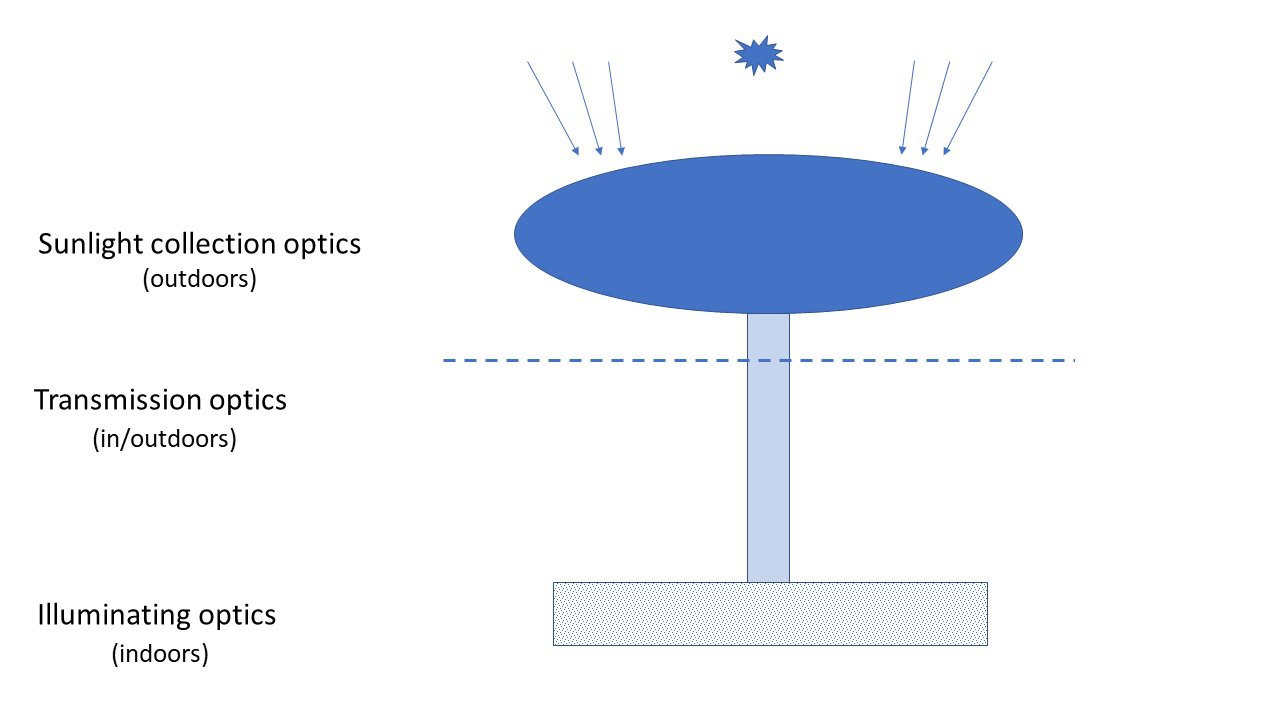 Figure 1
 Figure 2
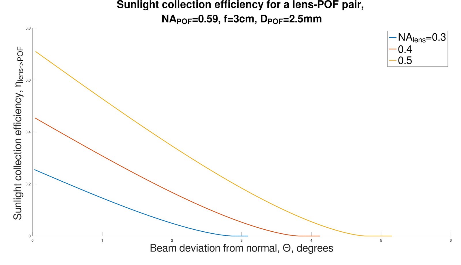 Figure 3
 Figure 4
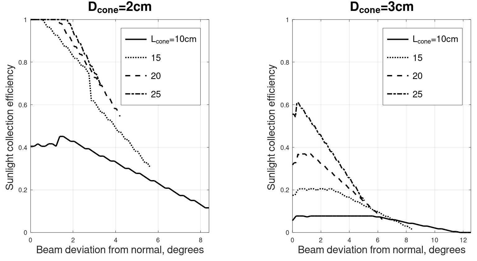 Figure 5
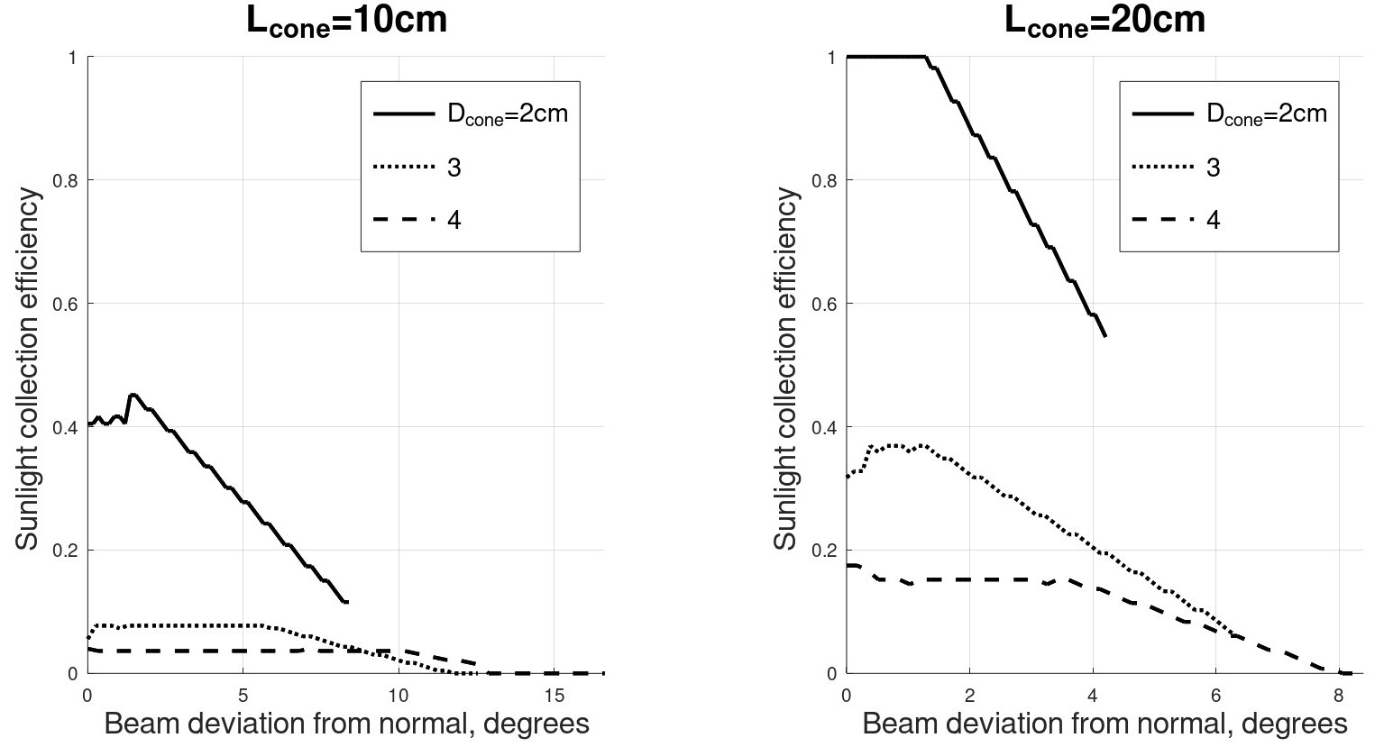 Figure 6
 Figure 7
 Figure 8
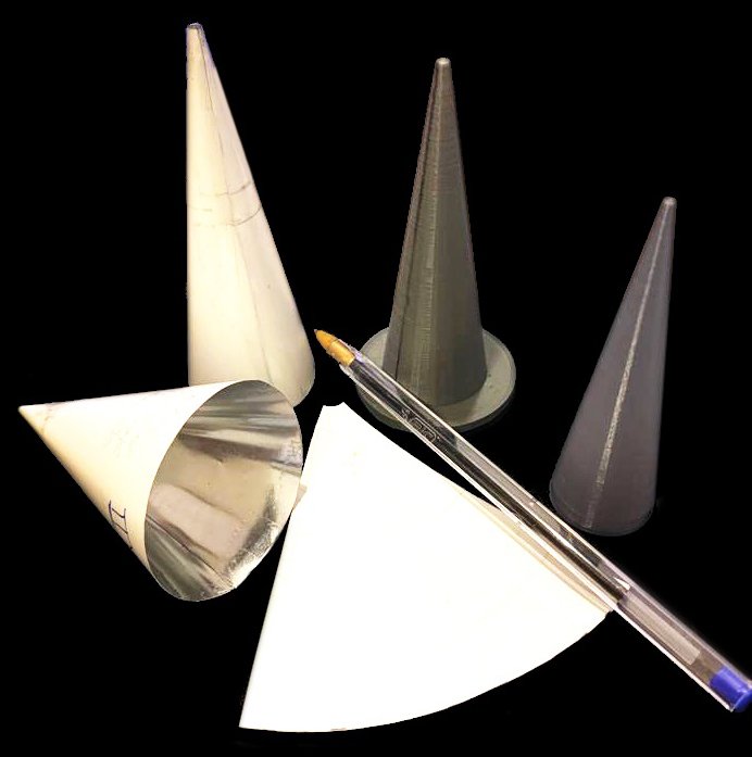 Figure 9
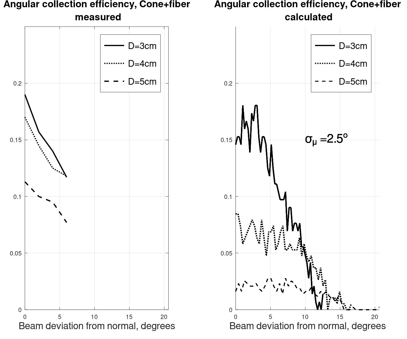 Figure 10
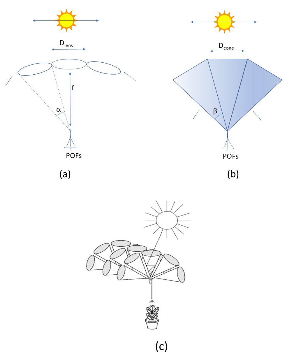 Figure 11
 Figure 12
 Figure 13
 Table 1


