Volume 4 Issue 2 pp. 26-36 • doi: 10.15627/jd.2017.5
Design and Optical Evaluation of a Novel Asymmetric Lens-Walled Compound Parabolic Concentrator (ALCPC) Integration with Building South Wall
Qingdong Xuan,a Guiqiang Li,a* Gang Pei,a,* Yuehong Su,b Jie Jia
Author affiliations
a Department of Thermal Science and Energy Engineering, University of Science and Technology of China, 96 Jinzhai Road, Hefei City 230026, China
b Institute of Sustainable Energy Technology, University of Nottingham, University Park, Nottingham NG7 2RD, UK
* Corresponding author. Tel: +86 551 63603512
qdxuan@mail.ustc.edu.cn (Q. Xuan)
ligq@mail.ustc.edu.cn (G. Li)
peigang@ustc.edu.cn (G. Pei)
yuehong.su@nottingham.ac.uk (Y. Su)
jijie@ustc.edu.cn (J. Ji)
History: Received 14 July 2017 | Revised 31 August 2017 | Accepted 3 September 2017 | Published online 4 September 2017
Copyright: © 2017 The Author(s). Published by solarlits.com. This is an open access article under the CC BY license (http://creativecommons.org/licenses/by/4.0/).
Citation: Qingdong Xuan, Guiqiang Li, Gang Pei, Yuehong Su, Jie Ji, Design and optical evaluation of a novel asymmetric lens-walled compound parabolic concentrator (ALCPC) integration with building south wall, Journal of Daylighting 4 (2017) 26-36. http://dx.doi.org/10.15627/jd.2017.5
Figures and tables
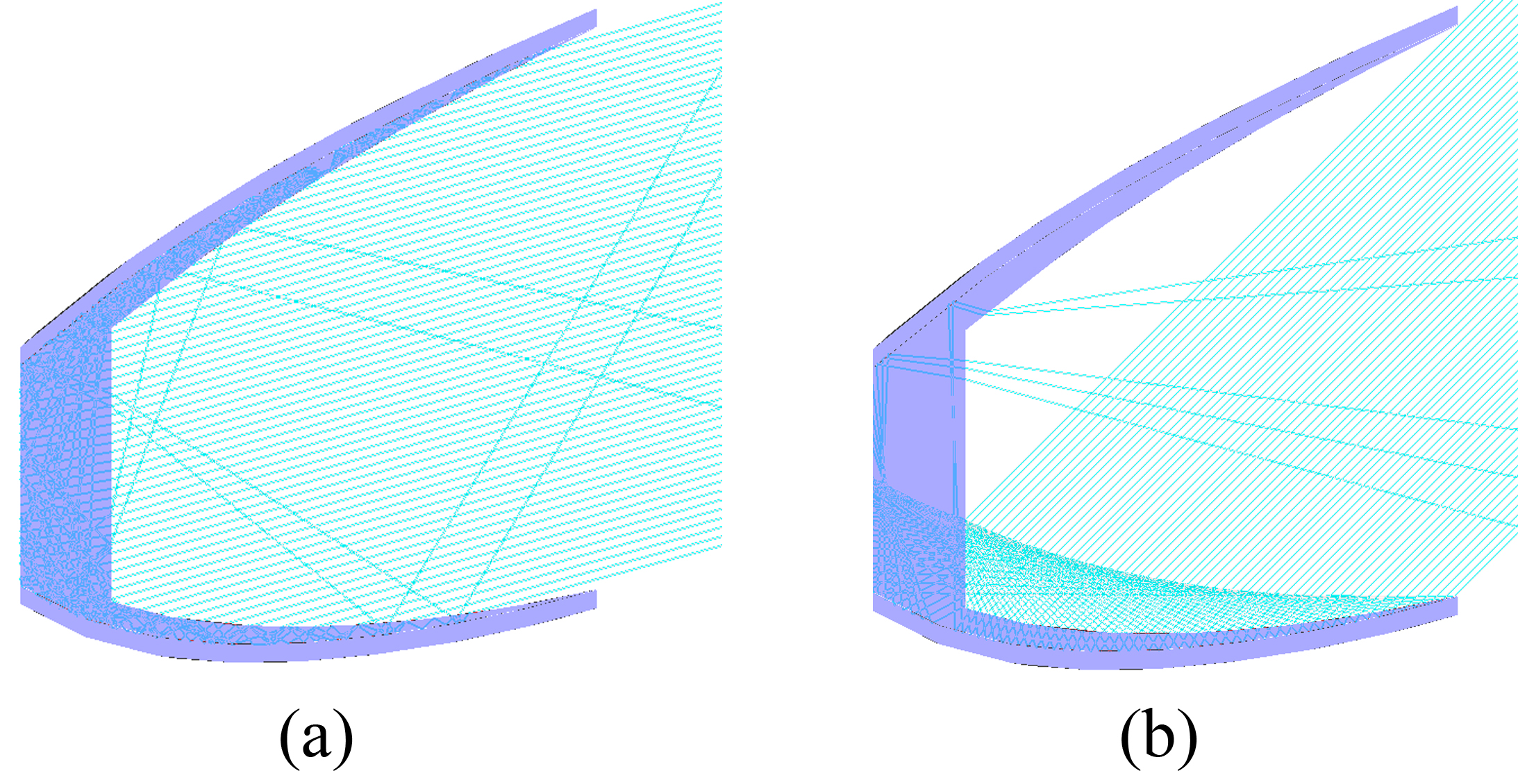 Figure 4
Abstract
Solar concentrating system is an effective way of combing solar energy with the building to satisfy the needs besides of electricity and hot water, also includes building heating, refrigeration, dehumidification, which require higher quality heat source. This paper put forward a novel static asymmetric lens-walled compound parabolic concentrator (ALCPC), which is composed of the mirror CPC and lens-walled structure, and can make full use of the total internal reflection and specular reflection. The optical performance of the ALCPC under the real application condition was established by software Lighttools®. Furthermore, the optimization structure by rotating the absorber away from the wall at some specific angles was also adopted for a wider scope applications. The results showed that the ALCPC has a large acceptance angle of 59° with highest optical efficiency of around 90% for most of the incident angles and has a relatively uniform flux distribution. In addition, annual performance analysis of the ALCPC was also done for Beijing (39°54’N, 116°23’E). The ALCPC as a static concentrator would be a good solution for the building south wall integration.
Keywords
Optical efficiency, Building south wall integration, Incidence angle, Flux distribution
Nomenclature
Lb |
luminance background (cd/m-2) |
Ls |
luminance of the glare sources (cd/m-2) |
B |
base height (mm) |
Cg |
geometrical concentration ratio |
d |
the length of the absorber (mm) |
h |
solar altitude angle (°) |
IPQ |
solar radiation on the south wall (Wm-2) |
IRS |
solar radiation on the ground (Wm-2) |
| Greek symbols | |
α |
latitude of position A (°) |
β |
latitude of position B (°) |
δ |
rotation angle of the lens-walled structure (°) |
ψ |
the longitude difference between position A and position B (°) |
φ |
the angle between unit vector \(\vec{OB}\) of sun ray and unit vector \(\vec{OA}\) (or \(\vec{AT}\))(°) |
λ |
rotation angle of the optimization structure of the ALCPC (°) |
θ |
incident angle of the original ALCPC (°) |
θ′ |
incident angle of the optimizing ALCPC (°) |
θNS |
N–S projected solar altitude angle (°) |
γs |
solar azimuth angle (°) |
1. Introduction
With the rapid development of the society, environment problems have become more and more serious. Solar energy as a kind of inexhaustible and clean energy has aroused an increasingly widespread attention. Nowadays, with the increase of the building energy consumption, solar energy may be one of the effective ways to alleviate the pressure on the traditional energy source for the building energy demand. The requirement includes not only the electricity and the hot water, but also the building heating, the refrigeration, and dehumidification, which require higher quality heat source, especially during winters [1-4]. However, due to the low intensity solar radiation, it becomes difficult to meet the above mentioned demands, therefore, building integrated concentrating Photovoltaic/thermal (BICPV/T) are found to be effective against any such constraints. [5-9].
However, there are reasonably appreciable features associated with building integrated solar concentrators, such as integration with building façade and roof without any sorts of tracking system or seasonal adjustment. They are found to have large acceptance angle and high optical efficiency with uniform flux distribution to ensure better electrical and thermal performance [10]. There are many researchers paid more attention on the static solar concentrators. T.K Mallick et al [11-13] designed a novel asymmetric CPC which consisted of two different parabolas, and the simulation and experiment results showed that is a feasible way to integrate it with building façade at Northern Ireland (54°36’N, 5°37’W) and the asymmetric geometry might be a better way to be used with building facade[11]. John R. Hull et al [14] proposed that using dielectric material to form dielectric CPC is an effective way to increase the half acceptance angle and optical efficiency by the means of refraction and total reflection. M. Sabry et al. [15] proposed a low-concentration facade integrated photovoltaic systems (LFP) by the truncation of the tiled CPC that is made from transparent acrylic CPC segments, which plays an effective role in reducing cooling loads inside buildings. Carlo Renno and Fabio Petito [16] presented a model for choosing the proper modular configuration of a point-focus concentrating Photovoltaic/thermal (CPV/T) system according to the domestic user energy demands, and the results showed that CPV/T systems allowed a significant reduction of CO2 emissions due to the primary energy savings. Milorad Bojic et al. [16] presented the investigations for three types of non-imaging, asymmetric, stationary seashell solar concentrator that use solar energy to generate heat by using CATIA software. Chr. Lamnatou et al. [6] conducted Life-cycle analysis of a concentrating Photovoltaic (CPV) for building-integrated applications for different cities. M.F.I. Al Imam et al. [18] analyzed the performance of PVT solar collector with compound parabolic concentrator and phase change materials for buildings.
For the solar concentrating system for the integration with buildings, the static solar concentrator is one of the core components. In the design of the static solar concentrator, the optical simulation based on the software is a key stage, which can provide an effective guarantee for the structure optimization. Nazmi Sellami et al. [19] used OptisWork software to design a Square Elliptical Hyperboloid (SEH) static concentrator which can be integrated in glazing windows or facades for photovoltaic application. Imhamed M. et al. [20] used the ray trace technique via OpticsWorks software to design a static 3D solar concentrator, called the Square Elliptical Hyperboloid. Firdaus Muhammad-Sukki et al. [1] designed a mirror symmetrical dielectric totally internally reflecting concentrator for building integrated photovoltaic systems through the ray tracing analysis in ZEMAX. Daniel Chemisana et al. [21] used a commercial computer program OptiCAD to simulate the optical system to determine the optimizing characteristics of the concentrators based in stationary linear Fresnel lenses and secondary CPC. Zheng et al. [22] and Tao et al. [23] used the software Lightools to make the ray- tracing analysis for the new solar concentrators. Su et al. [24] proposed the lens-walled structure for CPC based on the optical software Photopia. Li et al adopted the software Lightools to analyze the flux distribution of the lens-walled CPC [25] and design and optimize a lens-walled CPC with air gap [26]. Then Li et al. [27, 28] made the experiment to verify the optical simulation results from the software Lightools and confirmed the rationality of the optical design based on the software Lightools.
Recent researches for the static dielectric concentrator paid more attention on the symmetric concentrators for the application on the building roofs; however symmetric concentrators have their restrictions for integration with building façade. For some specific areas, it may be suitable for application while in other areas it may have many restrictions because of the different latitudes. For example, the symmetric lens-walled CPC is just suitable for the building roofs, and the asymmetric static dielectric concentrator for application on the building façade has been rarely studied in previous research. Therefore, for the building south-wall, the further design is still needed and necessary.
In order to overcome these problems, based on the previous design experience, in this paper, the novel prototype of an asymmetric lens-walled CPC (ALCPC) was proposed. The optical efficiency at different incidence angles and the influence of structure parameters on the optical efficiency were analyzed. In order to extend the range to lower latitude areas, the optimized structure was designed by rotating the ALCPC away from the wall, and the flux distribution was also analyzed. Annual performance analysis was also performed at Beijing (39°54’N, 116°23’E) to provide a potential analysis , and the ALCPC can keep almost 8-hour-solar-collection time every day, which indicated the ALCPC has a good performance as a static solar concentrator with the building south wall integration.
1. Preliminary design of the ALCPC
2.1. The structure of the ALCPC
The asymmetric lens-walled structure of the ALCPC is illustrated in Fig. 1. The profile can be described as following: the outer contour of the lens consists of two asymmetric compound parabola curves MP and NQ, and the half acceptance angles of them are 42°and 0°, respectively. Then the curves MP and NQ are truncated at P’ and Q’. The lens-walled structure is formed by rotating the curves MP’ and NQ’ around their top end points P’ and Q’ respectively toward the inside by a certain degree. The distance between MN and M’N’ is the base height. The geometrical concentration ratio of the ALCPC is 2.57X, according to Eq. (1). Detailed parameters are listed in Table 1.
where aperture width and base width are the length of P’Q’ and MN respectively according to Fig. 1, where base width is also marked as d.
Figure 1
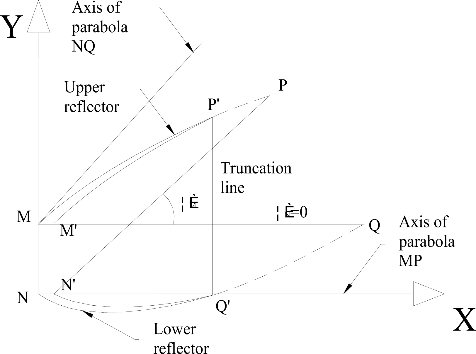
Fig. 1. Showing the lens-walled structure.
Table 1
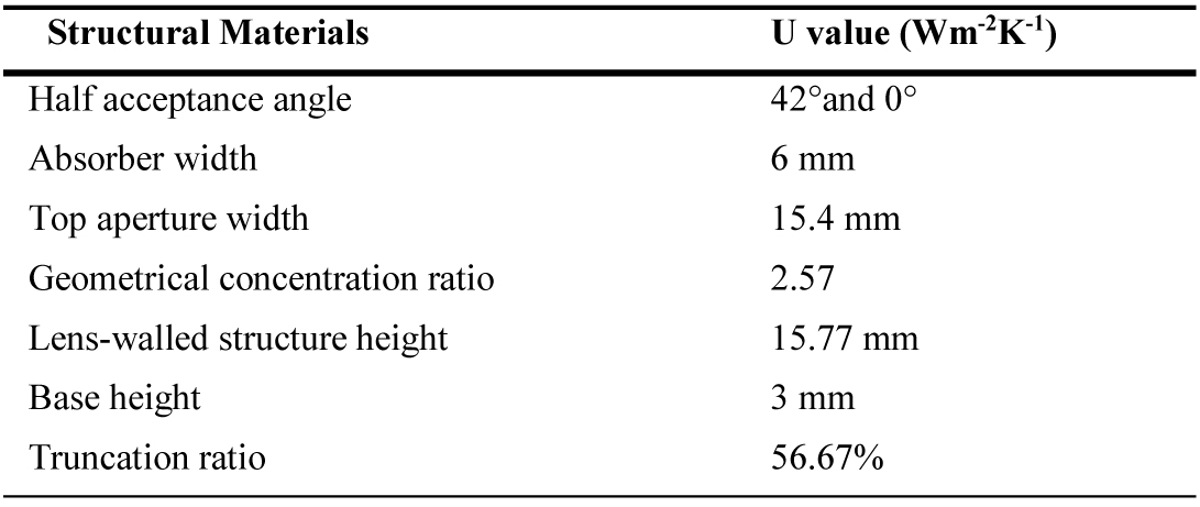
Table 1. Parameters of the lens-walled structure.
However, a part of the incident rays passing through the top aperture of the structure can not reach the absorber by the refraction and the total internal reflection, thus in order to collect these rays, a asymmetric mirror CPC is also integrated with the asymmetric lens-walled structure as an ALCPC, shown in Fig. 2.
Figure 2
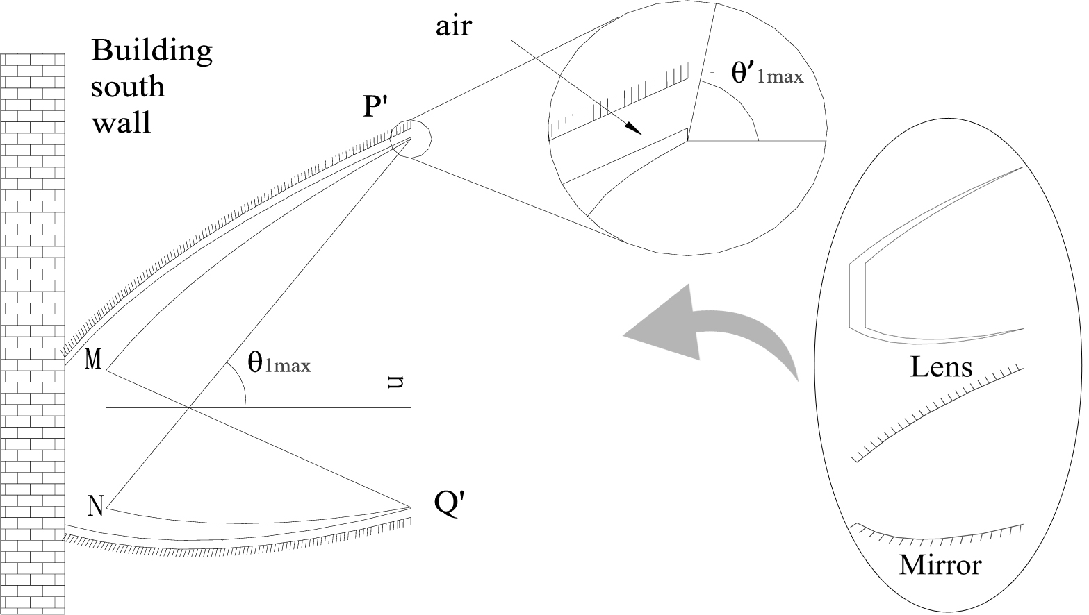
Fig. 2. Illustrating cross-section of the ALCPC.
2.2. Ray-tracing
Generally, the angle between the incident ray and the normal of the base is defined as the incident angle. For the asymmetric CPC integrated with the building south wall, the maximum acceptance angle is θ1max. For ALCPC, due to the refraction and total internal reflection, the maximum acceptance angle is θ1max' and it is clearly that,
The rays paths through the ALCPC may be more complex than the mirror CPC and it can be classified as four types (Fig. 3):
Figure 3

Fig. 3. (a-d) showing the diagram of the four kinds of ray paths.
- Rays reach the absorber directly without any specular refractions and reflections;
- Rays escape from the top aperture;
- Rays reach the absorber through the total internal reflection and the refraction;
- Rays reach the absorber through the specular reflection and the refraction.
In order to verify the optical performance of the ALCPC at different incidence angles, the commercial software Lighttools is used to simulate the incident rays passing through the ALCPC and then to get optical efficiency. Lighttools is a fast and accurate ray-tracing photometric analysis program which provides the optical system modeling and performance evaluation for non-imaging optical design. According to [10], the prediction of the optical efficiency of the symmetric lens-walled CPC can be within 5% of the experiment values.
Simulation parameters are listed in Table 2. The material of the ALCPC is set as PMMA and specular reflectivity is set to be 90%. The number of total incident rays is 10000 and the intensity of the solar radiation is 1000 Wm-2. All the incident rays are assumed to be parallel and the schematic diagram of ray trace simulation at the incidence angles of 15° and 45° are shown in Fig. 4. It’s obvious that the incidence angle of 45° is larger than the maximum acceptance angle of the mirror CPC with the same geometrical concentration ratio, but the lens-walled structure may turn the sunrays coming at a larger incidence angle into a direction within the acceptance angle of the ALCPC, so the ALCPC can absorb many sunrays at the incidence angle of 45°.
Table 2
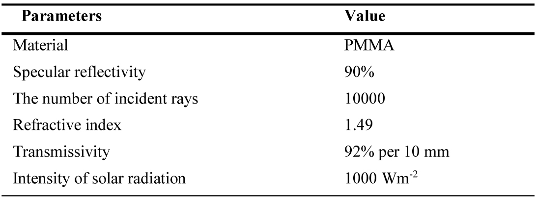
Table 2. Simulation parameters
Figure 4
Fig. 4. Schematic diagram of ray trace simulation at incidence angle of (a) 15° and (b) 45°.
2.3. Structure parameters analysis
2.3.1. Base height
Referring to the symmetric lens-walled CPC, the optimum rotation angle was confirmed to be 3° [24], so it will be chosen as the rotation angle of the ALCPC to analyze the effects of the base height. In general, the base height should be smaller in order to decrease the material and weight; however, since many rays will undergo the refraction and the total internal reflection, the base height may influence the ray path close to the absorber. Therefore, it is of great importance to determine the base height for the ALCPC reasonably. In order to compare and analyze the influence of the base height, the optical efficiency at different incidence angles with the base height of 1 mm, 1.5 mm, 2 mm, 2.5 mm, 3 mm, 3.5 mm, 4 mm, 4.5 mm, and 5 mm are presented in Fig. 5.
Figure 5
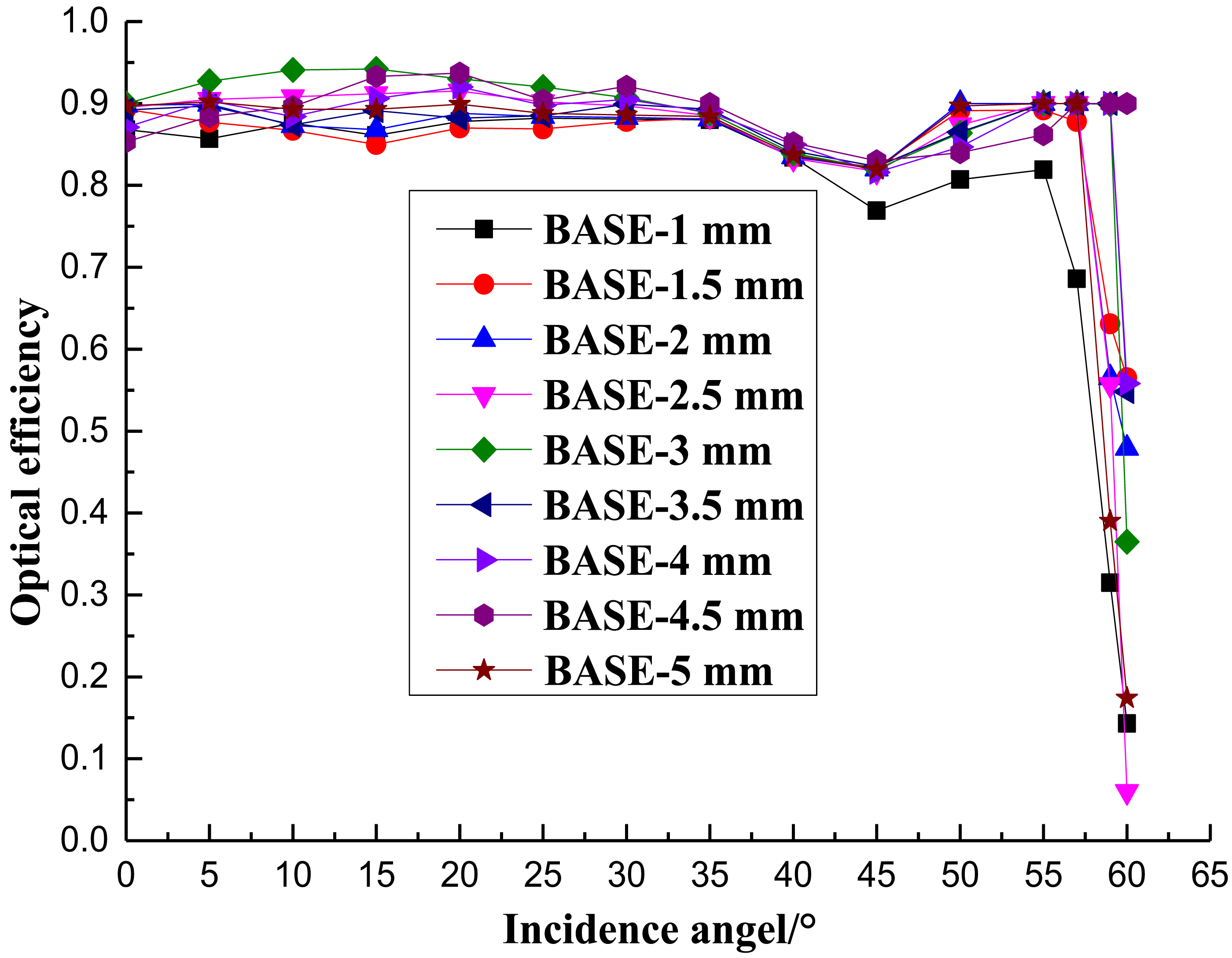
Fig. 5. Optical efficiency of the ALCPC with different base heights.
It can be seen from Fig. 5 that the difference values between the highest optical efficiency and the lowest optical efficiency can be up to 10% at the same incidence angle. With the increase of the base height from 1 mm to 3 mm the optical efficiency increases, and when the base height is greater than 3 mm, the optical efficiency decreases, so it can be concluded that the base height of 3 mm is more suitable for the ALCPC with consideration of the optical performance, the weight, the cost and the portability.
2.3.2. Rotation angle
Based on the base height of 3 mm, the optical efficiency of a 2.57X ALCPC with different rotation angles between 3° and 6° are given, as shown in Fig. 6. With the increase of the rotation angle, the optical efficiency decrease slightly. However, because of the fabrication difficulties, high rotation angles such as 5° and 6° are easier to make compared with others. Therefore, the asymmetric lens-walled CPC with the rotation angle of 5° has more advantages for the actual application.
Figure 6
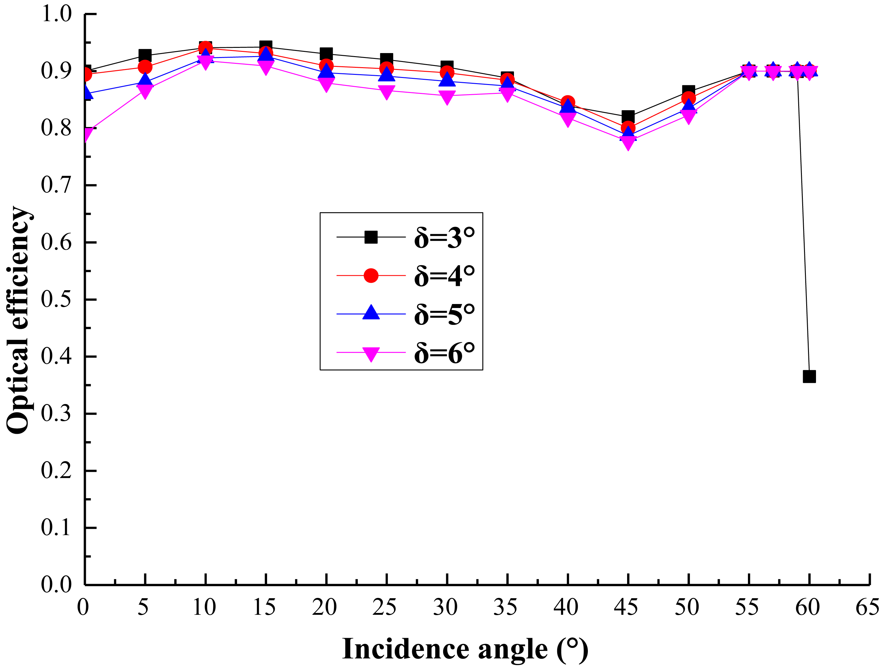
Fig. 6. Optical efficiency of the ALCPC with different rotation angles.
Based on the parameters analysis above, the energy collected by the absorber and the rays reached the absorber of the ALCPC with b=3 mm and δ=5° at different incident angles are shown in Fig. 7. It reveals that the maximum acceptance angle of the ALCPC is 59° with the highest optical efficiency around 90% except for some incidence angles such as 45° because of the escape of some incident rays. The curve of the rays reaching the absorber is relatively higher than that of the energy collected by the absorber that is due to the optical losses in the transmission process.
Figure 7

Fig. 7. The energy collected by the absorber and the rays reach the absorber of the ALCPC with b=3 mm and δ=5°.
3. Building integration analysis
The ALCPC is designed for the building south wall integration, and in this article, the performance of the ALCPC for the east-west orientation is discussed. For the E–W orientation, the solar radiation vector may be divided into one component in the east–west direction and other component on the vertical plane oriented north–south, as shown in Fig. 8. The direct irradiance on a surface facing south is determined by the component on the vertical plane only, since the component in the east–west direction is parallel to the receiving surface and will not contribute to the solar energy absorption through the surface [29].
Figure 8
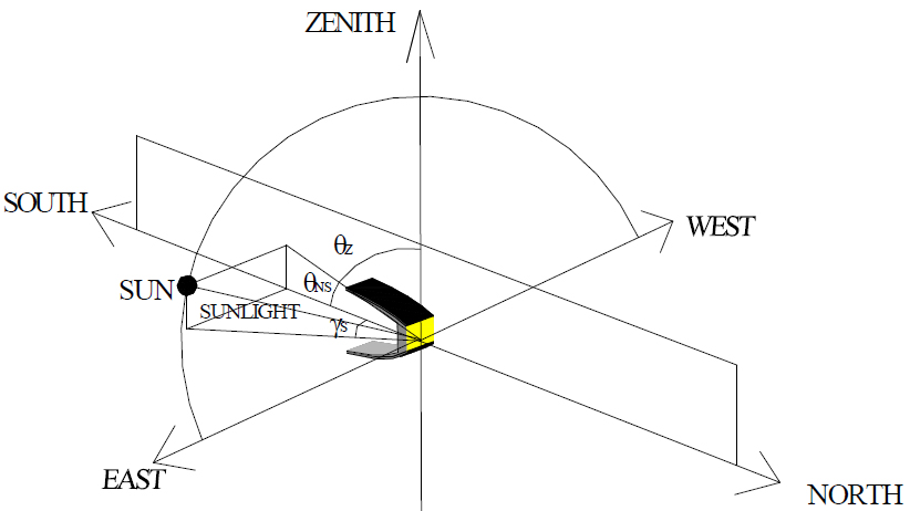
Fig. 8. Solar position diagram for the E-W orientation of a building south wall integration ALCPC.
The angle between the horizon and the projection of the solar radiation vector on the north–south vertical plane θNS may be called as the N–S projected solar altitude angle. The difference between the N–S projected solar altitude angle and (90 deg-the tilt angle) is the projected incidence angle to the aperture of a CPC for E–W orientation. The mathematical expression is [10]:
where h - solar altitude angle equal to (90-solar zenith angle θz); γs - solar azimuth angle; θNS - N–S projected solar altitude. It is clearly that the projected solar altitude angle equals to the projected solar incidence angle for the ALCPC.
At the different latitudes, different time in a day or in a month, the sun's position in the sky varies a lot. It is necessary to obtain h and γs before we can determine θNS at the specific latitude and time. In this article, the vector method is used to calculate h and γs and then to get θNS.
As shown in Fig. 9(a), position A is where the ALCPC is set up while the sun rays perpendicularly pass through the position B. The meridians through position A and B intersects with the equator at D and C, respectively. The angle between OD and OC ψ is the longitude difference between position A and position B that is also called sun hour angle. The center of the earth is set as the origin to form the space rectangular coordinate system.
Figure 9

Fig. 9. (a-c) Diagram for the calculation of θNS.
In the uraology system, a celestial sphere is used to measure the position of the celestial body. The point A is set as the origin and the horizontal circle WSE of position A is set as one of the great circles to make the celestial sphere as shown in Fig. 9(b) where T and T’ are the zenith and the nadir of it, respectively. S is in the south direction of position A, and F is the position of the sun at the celestial sphere of position A. Thus, \(\vec{AT}\) is vertical to the horizontal circle of position A which is also the normal vector of position A. AF is the sun ray which passes through position A, and F’ is the orthographic projection of F on the ground A. From above description, it can be see that the angle between AF and AG is the solar altitude angle h, and the angle between AS and AG is the solar azimuth angle γs.
In Fig. 9(c), circle O is the great circle of the earth that passes through both position A and B. H is the projection of T on the ground A, \(\vec{HT}\) ∥ \(\vec{BO}\) Therefore, ∠AOB=∠ATH=φ, ∠AHT=h=90°-φ which is the solar altitude angle of position A.
In Fig. 9(a), unit vector \(\vec{AS}\) is the tangent of the meridian through A and points to the south direction, and unit vector \(\vec{AE}\) is the tangent of the weft through A and points to the east direction. At position A, the ground plane of position A is determined by unit vector \(\vec{AS}\) and \(\vec{AE}\)∙\(\vec{AF}\) is the unit vector of the sun ray, and \(\vec{AF}\) is orthographic projection of \(\vec{AF}\) on the ground A, Thus|AF'|= cos h, γs=∠ASF'. Unit vector \(\vec{OA}\) is collinear with \(\vec{AT}\) and φ is the angle between unit vector \(\vec{OB}\) of the sun ray and unit vector \(\vec{OA}\) (or \(\vec{AT}\).
As it is shown in Fig. 9(a), in the coordinate system O-xyz, A (cosα, 0, sinα), B (cosβcosψ, cosβsinψ, sinβ). \(\vec{OA}\) (cosα, 0, sinα), \(\vec{OB}\) (cosβcosψ, cosβsinψ, sinβ). \(\vec{OD}\) (1, 0, 0), (ON) ⃗ =( 0,0,1 ). \(\vec{AE}\)⊥\(\vec{OD}\), \(\vec{AE}\)⊥\(\vec{ON}\), \(\vec{AS}\)⊥\(\vec{OA}\) thus:
So it can be gotten that \(\vec{AE}\) (0, 1, 0), \(\vec{AS}\) (sinα, 0, -cosα).sinh= sin(90°-φ) = cosφ= cos〈\(\vec{OA}\), \(\vec{OB}\)〉, thus:
As it is shown in Fig. 9(b), AS, AE and AT’ are set as X’ axis, Y’ axis and Z’ axis, respectively, and point A is set as the origin to form the coordinate system A-x’ y’ z’. Given \(\vec{AF'}\)=(x’, y’, 0), \(\vec{OA}\)=\(\vec{OB}\)=(cosβcosψ, cosβsinψ, sinβ), it can be seen clearly that x’=cos∠SAF =cos〈\(\vec{AS}\), \(\vec{AF}\)〉:
Thus, x'= sinαcosβcosψ-cosαsinβ.
From above calculation, the relationship between h, γs and α, β, ψ are determined. So the incident angle of the ALCPC can be expressed as:
In order to choose the proper ALCPC for different latitudes to collect more solar energy thus to make full use of it in one year, incident angle of the ALCPC when integrating with building south wall at different time of the year should be determined using Eq. (10). Declination angle β is a function of day number, regardless of the location, and is given by the equation [10]:
where n is the day number, counting from New Year’s day, that day is 1. For example, if the date is 23th March, n=82, β=2.57°.
Figures 10 and 11 show the equivalent solar incidence angle θNS of different latitudes, for example, Haikou (20°N, 110°10’E), Hefei (31°52’N, 117°17’E) and Haerbin (46°40’N, 125°42’), Nottingham (52°56’N, 1°10’W), and Are (63°N, 13°04’E) represent the low, medium and high latitude areas respectively, when the sun rays perpendicularly pass through the Tropic of Cancer(solstice) and pass through the equator(equinox).
Figure 10
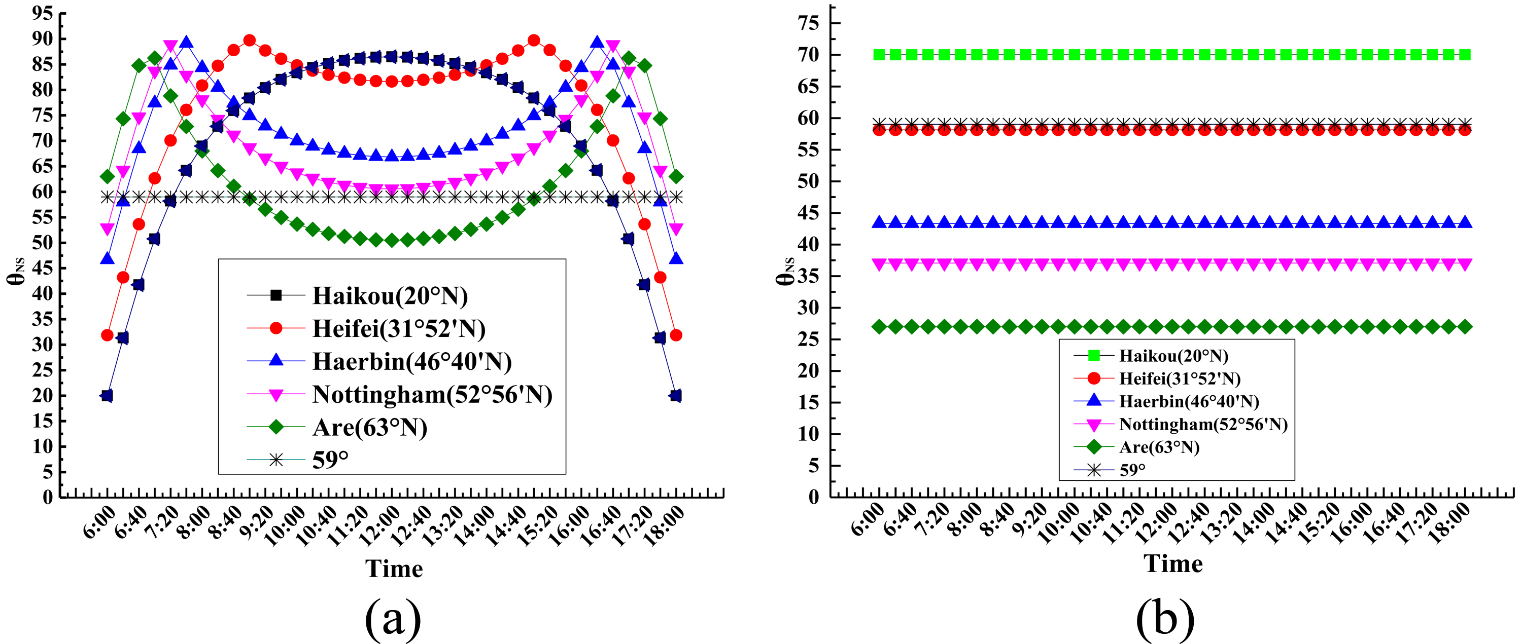
Fig. 10. Incident angle when the sun rays perpendicularly pass through the (a) Tropic of Cancer (solstice) and (b) equator (equinox).
Figure 11
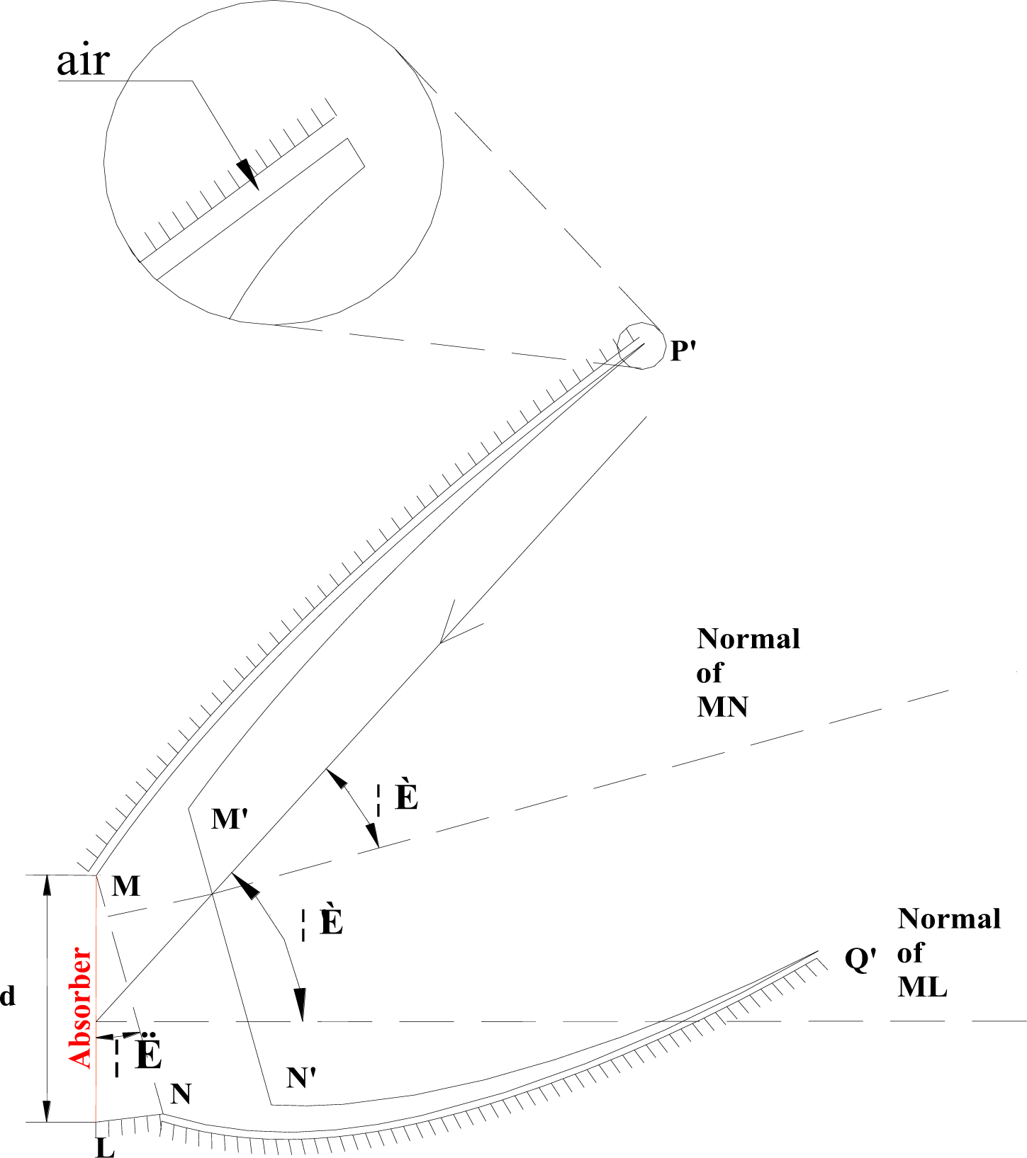
Fig. 11. Optimization structure of the ALCPC.
Figure 10 reveals that the solar equivalent incidence angle θNS increases with the increase of the declination angle β and when the sun rays perpendicularly pass through the Tropic of Cancer it reaches the peak value. In the Northern Hemisphere, the solar equivalent incidence angle, θNS, is very large in the summer time and the lower latitude is corresponding to the larger solar equivalent incidence angle, θNS. It can be seen clearly from Fig. 10(a), when the sun rays perpendicularly pass through the Tropic of Cancer (solstice), the solar equivalent incidence angle of the latitude lower Hefei (31°52’) can be close to 90° at the solar concentrator can not absorb the sun rays. Therefore, it may not be a suitable choice to integrate the ALCPC with south wall in low latitude areas if the aim is to accomplish the whole year solar collection.
4. Further optimization
4.1. Optimization of the structure of the ALCPC to increase incidence angle
From the discussion above, it can be concluded that the ALCPC is suitable for integration with the building south wall in high latitude areas due to it is high optical efficiency and large acceptance angle. However, in lower latitude areas, the incidence angles can be very large during the summer time, so in these areas it’s not suitable to use it due to the restriction of acceptance angle. In order to further expand the use of the ALCPC at wider range of areas, the further optimization structure of the ALCPC is adopted, and it is shown in Fig. 11.
As shown in Fig. 11, the optimization structure is formed by rotating the original ALCPC around the up end point M away from the wall ML by a certain angle λ. Then the profilogram is MLNQ’N’M’P’M. Attaching the absorber of the ALCPC to the building south wall still has many advantages such as easy arrangement, sufficient utilization, etc. Thus, the acceptance angle of the new ALCPC will be , which means that the acceptance range from 0-59° extends to λ - λ + 59°. For example, if the rotation angle is 15°, the acceptance range will be 15-74°.
In addition, after the rotation, it may be useful to minish the length of ML to increase the geometric concentration ratio without change of the structure of the ALCPC. Figure 12 shows the change of the geometric concentration ratio with the decrease of the length of ML, and the geometric concentration ratio can increase from 2.57X to 3.1X with the length of the absorber decreases from 6 mm to 5 mm. It is obvious that it is an effective way to increase geometric concentration ratio without any change of the structure of the ALCPC.
Figure 12
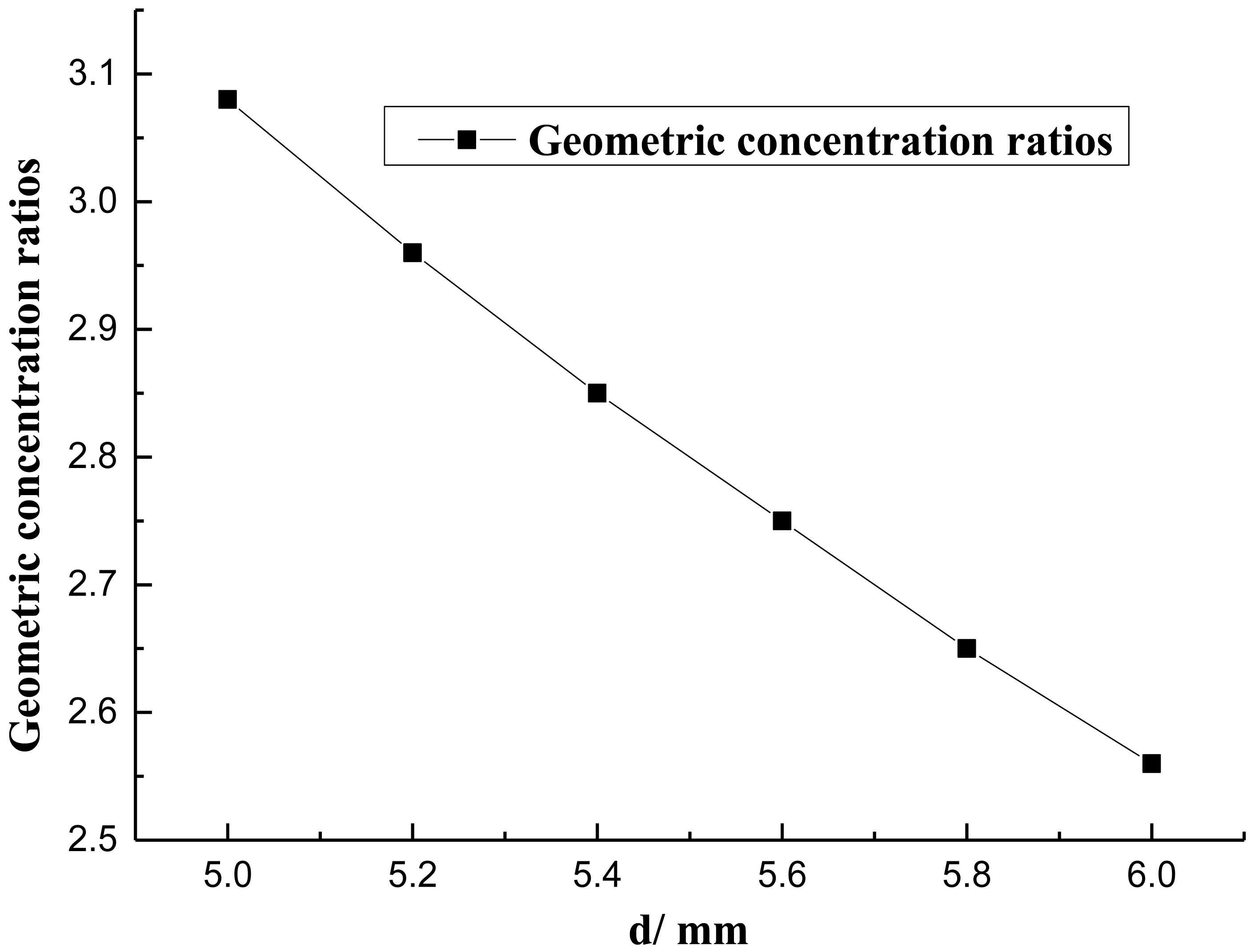
Fig. 12. Geometric concentration ratio of the ALCPC with different d.
4.2. The effects of d (the length of ML: mm) and on the optical efficiency of the ALCPC
Although the rotation of the original ALCPC is an effective way to enlarge the acceptance range, the optical performance is still the one of the most important factors. Therefore, the optical simulation of the ALCPC with different d and λ under different incidence angles is necessary and important, and the corresponding optical efficiency is depicted in Fig. 13. From the results, optimization structures with rotation angle λ=5°, 10°, 15°and d=6 mm have higher optical efficiency than the original ALCPC while when λ=20° the optical efficiency is a little lower than the original ALCPC. The optical efficiency decreases with the decrease of d and it can be lower than 70% when d=5 mm at some incidence angles, so even if the way of decreasing d can increase the geometric concentration ratio, d=5 mm still should not be chosen. But for some rotation angles, it even increases the optical efficiency, so it is a feasible and effective way to enlarge the range of acceptance angles.
Figure 13
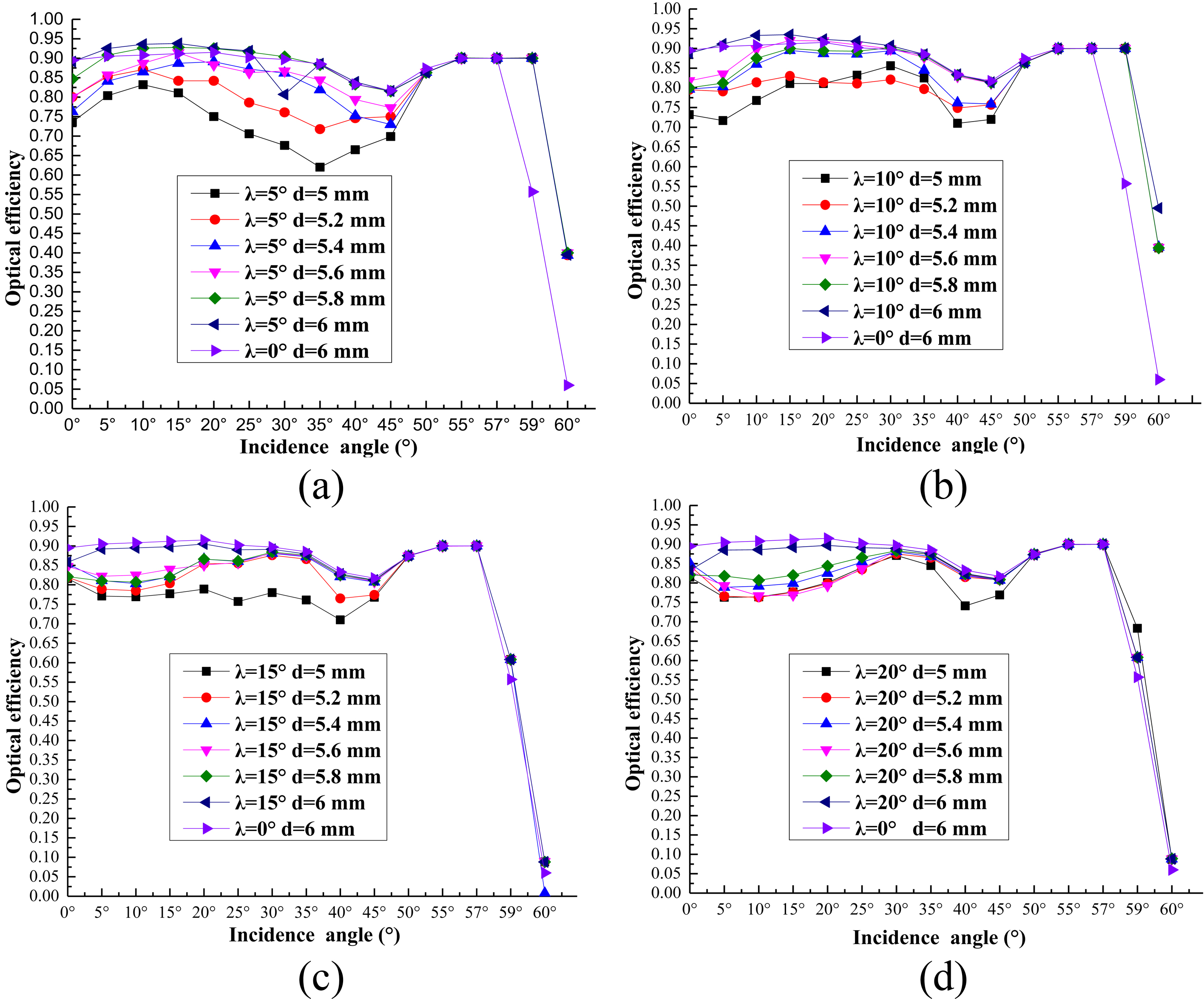
Fig. 13. Optical efficiency of the ALCPC for (a) λ = 5°, (b) λ = 10°, (c) λ = 15°, and (d) λ = 20°.
4.3. Flux distribution of the ALCPC
In order to analysis the flux distribution of the ALCPC, the simulation on flux distribution was carried out for the ALCPC with different d and λ. The simulation results show that parameters d and λ have little influence on flux distribution and it only varies with the incident angles. The flux distribution of the ALCPC with d=6 mm and λ=5° at the incidence angles of 10°, 20°, 45° and 55° are chosen to be revealed by average local concentration ratios (Fig. 14).
Figure 14

Fig. 14. Averaged local concentration ratios of the ALCPC with d=6 mm and =5° at the incidence angle of 10°, 20°, 45° and 55°. The distance is counted from L (Fig. 12).
From the results, it can be seen that at the lower incidence angles such as 10°, 20°, the flux distribution on the absorber of the concentrator is very uniform with a very small change tendency while due to the special asymmetric structure of the ALCPC, when incidence angle is very large such as 55°, it’s unavoidable that the rays can only reach one side of the absorber which results in some positions of the absorber can’t collect any rays. Compared to the symmetric lens-walled CPC, whose flux distribution simulation research work performed by li et al. [25] which revealed that the lens-walled CPC has mitigated the non-uniformity of the CPC flux distribution and the flux distribution of the ALCPC has the similar advantage at many incidence angles. Therefore, it can be predicted that the ALCPC may have a better flux distribution than the mirror CPC when integrating with building south wall based on the optical simulation.
5. Annual performance analysis
From the structure optimization analysis mentioned above, it is a better way to adopt this new kind of ALCPC in lower latitude areas. In order to show the actual performance of the ALCPC, an annual analysis for collecting solar radiation is significant and necessary. The simulation was conducted by considering both of direct and diffuse solar radiation on the surface of the ALCPC, and the results from Lighttools (simulation software [30]) determine the optical efficiency for diffuse component of solar radiation is about 50%. Beijing (39°54’N, 116°23’E) is selected to analyze the annual performance, and solar projected incidence angles in Beijing for different dates are shown in Fig. 15. It reveals that the incidence angles of the direct solar rotation in the whole year are between 20° and 80°, so that λ is better to be 20° to keep 8-hour-solar-collection time every day. Meteorological data was from EnergyPlus.
Figure 15
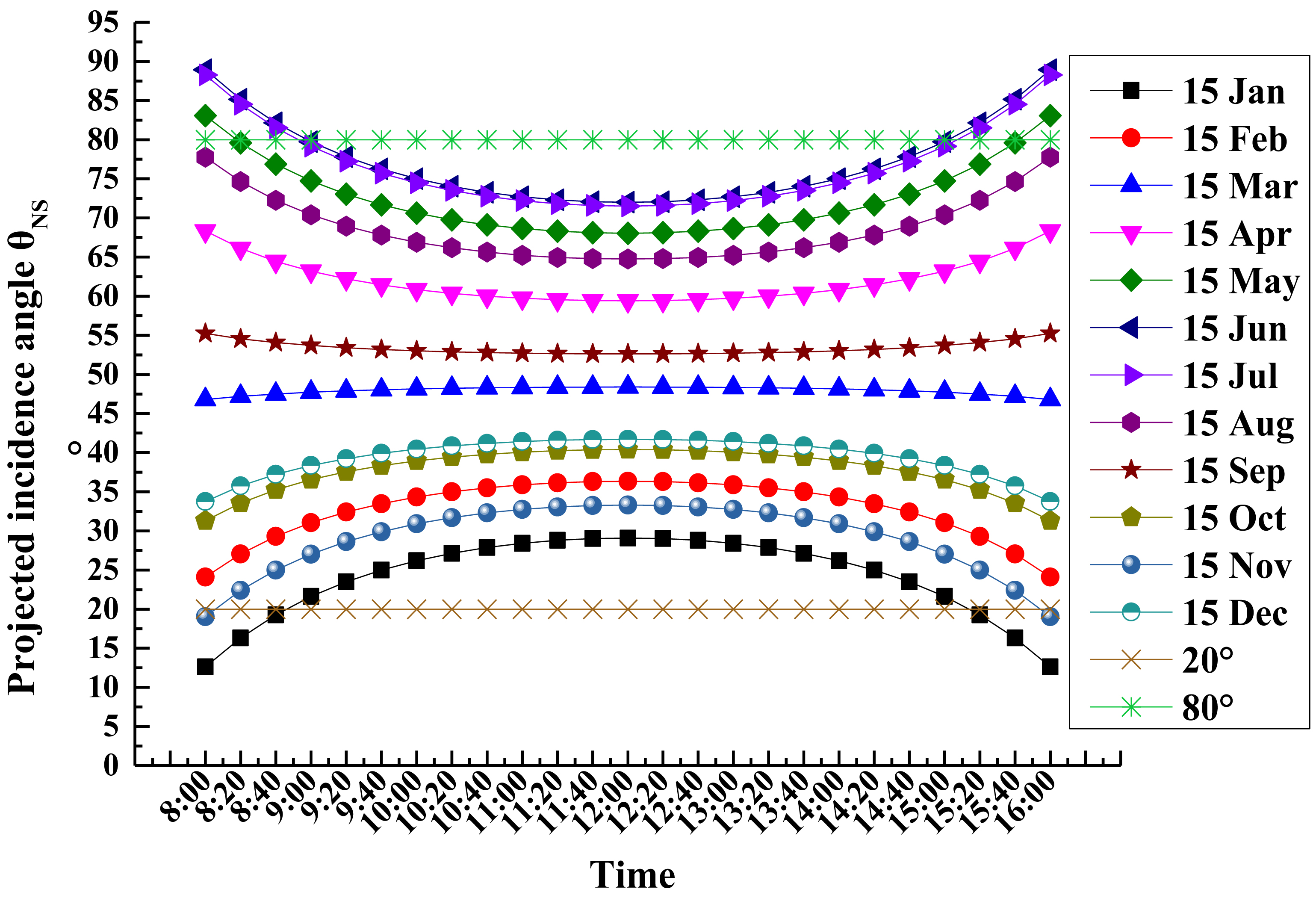
Fig. 15. Solar projected incidence angle θNS in Beijing of one year.
Accumulative collected solar radiation per m2 for Beijing is shown in Fig. 16. From the results, from August to December and from December to April, the accumulative collected solar radiation is much higher than in the months from May to July. In June, it reaches peak valley and in January it reaches peak. It arouses the question that why in the summer season when the solar radiation is strongest collects minimum solar energy in a year (Fig. 16). Solar radiation intensity on the ground is always used to make an evaluation but the solar radiation intensity on the building south wall is of much difference with it on the ground. To simplify the analysis, the sun ray vector on the N-S vertical plane is considered only. From Fig. 17, the solar radiation passes through the area PQ of the wall while the same solar radiation passes through the area RS of the ground, so solar radiation intensity will be different due to the different areas. It can be expressed by:
where IPQ is the solar radiation on the south wall, IRS is the solar radiation on the ground, and h is the solar altitude angle. Thus, with the increase of h the solar irradiation on the wall decreases. As for Beijing, when h is large in the summer, the solar radiation on the wall is lower than that on the ground.
Figure 16
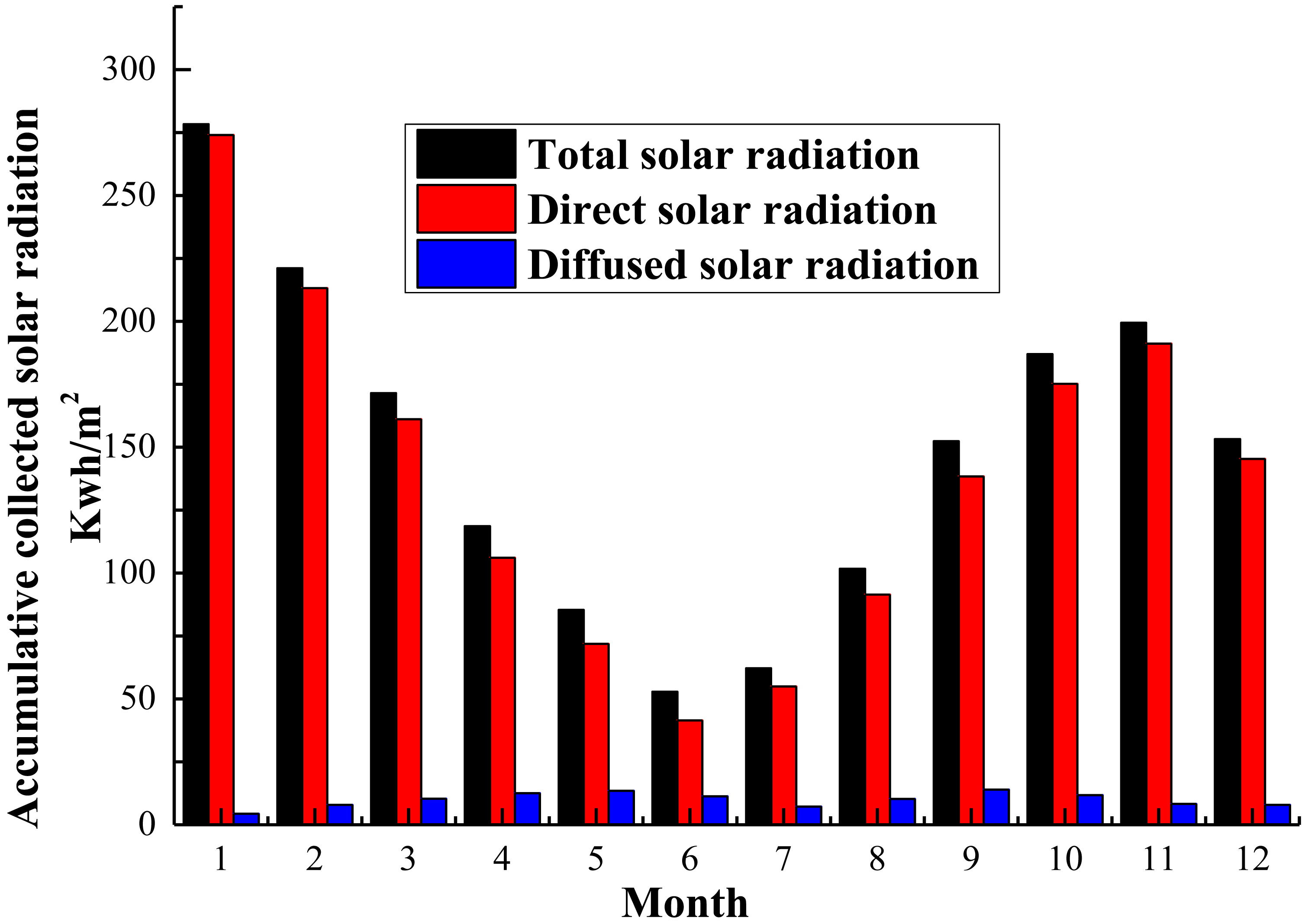
Fig. 15. Solar projected incidence angle θNS in Beijing of one year.
Figure 17

Fig. 17. Schematic diagram of the solar radiation on the wall and on the ground.
Although during the summer months the ALCPC collects fewer energy than during the winter months, it does not need to provide the thermal energy for the building heating. However, in the winter the heat collected by the ALCPC needs to satisfy both the requirement of heating the room to make a comfortable environment and the requirement of the domestic hot water for daily use. But in the summer, it just needs satisfy the requirement of the domestic hot water. In addition, it also can prevent the heat getting into the room and reduce the load of air conditioner in the summer.
6. Conclusions
A novel asymmetric lens-walled CPC designed for building south wall integration was proposed and analyzed. The ALCPC combined the mirror CPC and lens-walled structure, thus the sun rays can be collected by both the specular reflection and the total internal reflection which will increase the optical performance of the concentrator. The prototype of the ALCPC model is established in SolidWorks and then transferred into Lightools to set up the optical model for ray tracing simulation. Vector method is used to calculate the incidence angles of the sun rays in one year to provide a preliminary analysis of the feasibility of integrating the ALCPC on the building south wall. It is clearly that the incidence angles for different areas may vary a lot, in order to use the ALCPC at a wider scope of areas, the structure optimization is adopted. The key conclusions from the ray tracing simulation results are as follows:
- The results show that the ALCPC and its optimization structure have a large acceptance angle close to 60° with highest optical efficiency around 90%, which would provide a better choice for building south wall integration as a static concentrator.
- From the parameters analysis, decreasing the length of the absorber can increase the geometric concentration without any change of the ALCPC that it will further enhance the performance of the BICPV or BICPV/T.
- The flux distribution analysis is also conducted, and the results reveal that at lower incidence angles, the flux distribution is very uniform with a very small change tendency, and only at higher incidence angles, the flux distribution appear the non-uniformity, which is unavoidable for the asymmetric concentrator.
- Annual performance analysis is also performed for Beijing (39°54’N116°23’E), and the ALCPC can keep almost 8-hour-solar-collection time every day, which confirms the feasibility of the practical application.
In addition, from the analysis of the optical efficiency, flux distribution and annual performance for the ALCPC and its optimization structure, the paper provides the feasible and effective steps to choose the proper design of the ALCPC for specific areas which are: 1. Calculating the incidence angles of the direct solar radiation in the whole year according to Eq. (10); 2. Determining the rotation angle to match the range of the solar incidence angle in step 1 to keep more solar radiation collecting time.
Through the simulation work, the ALCPC as a static concentrator is confirmed to be a good solution for the building south wall integration. The further work about the BICPV or BICPV/T system design, optimization and practical engineering is worthwhile.
Acknowledgements
The study was sponsored by the National Science Foundation of China (Grant Nos. 51408578, 51476159, 51611130195), Anhui Provincial Natural Science Foundation (1508085QE96). The authors would like to thank Prof. Zheng Hongfei (School of Mechanical Engineering, Beijing Institute of Technology, China) for his assistance in the software simulation.
Contributions
G. Q. Li and G. Pei conceived the study. Q. D. Xuan performed the simulation work with the guidance by Y. Su and wrote the paper. J. Ji helpeG. Q. Li and G. Pei conceived the study. Q. D. Xuan wrote the paper and performed the simulation work with the guidance by G. Q. Li, Y. H. Su and J. Ji. All authors discussed the results and commented on the manuscript.
References
- F. Muhammad-Sukki, S. H. Abu-Bakar, R. Ramirez-Iniguez, S. G. McMeekin, B. G. Stewart, N. Sarmah, T. K. Mallick, A. B. Munir, S. H. M. Yasin, and R. A. Rahim, Mirror symmetrical dielectric totally internally reflecting concentrator for building integrated photovoltaic systems, Applied Energy 113 (2014) 32-40. https://doi.org/10.1016/j.apenergy.2013.07.010
- C. Feng, H. Zheng, R. Wang, X. Yu, and Y. Su, A novel solar multifunctional PV/T/D system for green building roofs, Energy Conversion and Management 93 (2015) 63-71. https://doi.org/10.1016/j.enconman.2015.01.001
- S. Bahria, M. Amirat, A. Hamidat, M. El Ganaoui, and M. E. A. Slimani, Parametric study of solar heating and cooling systems in different climates of Algeria – A comparison between conventional and high-energy-performance buildings, Energy 113 (2016) 521-535. https://doi.org/10.1016/j.energy.2016.07.022
- V. Drosou, P. Kosmopoulos, and A. Papadopoulos, Solar cooling system using concentrating collectors for office buildings: A case study for Greece, Renewable Energy 97 (2016) 697-708. https://doi.org/10.1016/j.renene.2016.06.027
- K. Connelly, Y. Wu, J. Chen, and Y. Lei, Design and development of a reflective membrane for a novel Building Integrated Concentrating Photovoltaic (BICPV) ‘Smart Window’ system, Applied Energy 182 (2016) 331-339. https://doi.org/10.1016/j.apenergy.2016.07.125
- C. Lamnatou, H. Baig, D. Chemisana, and T.K. Mallick, Life cycle energy analysis and embodied carbon of a linear dielectric-based concentrating photovoltaic appropriate for building-integrated applications, Energy and Buildings 107 (2015) 366-375. https://doi.org/10.1016/j.enbuild.2015.08.030
- T. Yang and A. K. Athienitis, A review of research and developments of building-integrated photovoltaic/thermal (BIPV/T) systems, Renewable and Sustainable Energy Reviews 66 (2016) 886-912. https://doi.org/10.1016/j.rser.2016.07.011
- S. Sharma, A. Tahir, K.S. Reddy, and T. K. Mallick, Performance enhancement of a Building-Integrated Concentrating Photovoltaic system using phase change material, Solar Energy Materials and Solar Cells 149 (2016) 29-39. https://doi.org/10.1016/j.solmat.2015.12.035
- Q. Xu, Y. Ji, B. Riggs, A. Ollanik, N. Farrar-Foley, J. H. Ermer, V. Romanin, P. Lynn, D. Codd, and M. D. Escarra, A transmissive, spectrum-splitting concentrating photovoltaic module for hybrid photovoltaic-solar thermal energy conversion, Solar Energy 137 (2016) 585–593. https://doi.org/10.1016%2Fj.solener.2016.08.057
- G. Li, G. Pei, M. Yang, J. Ji, and Y. Su, “Optical evaluation of a novel static incorporated compound parabolic concentrator with photovoltaic/thermal system and preliminary experiment,” Energy Conversion and Management 85 (2004) 204–211. https://doi.org/10.1016%2Fj.enconman.2014.05.082
- T. K. Mallick, P. C. Eames, T. J. Hyde, and B. Norton, The design and experimental characterisation of an asymmetric compound parabolic photovoltaic concentrator for building façade integration in the UK, Solar Energy 77 (2004) 319–327. https://doi.org/10.1016%2Fj.solener.2004.05.015
- T. K. Mallick, P. C. Eames, and B. Norton, Non-concentrating and asymmetric compound parabolic concentrating building façade integrated photovoltaics: An experimental comparison, Solar Energy 80 (2006) 834–849. https://doi.org/10.1016%2Fj.solener.2005.05.011
- T. MALLICK and P. EAMES, Design and fabrication of low concentrating second generation PRIDE concentrator, Solar Energy Materials and Solar Cells 91 (2007) 597–608. https://doi.org/10.1016%2Fj.solmat.2006.11.016
- J. R. Hull, Dielectric compound parabolic concentrating solar collector with a frustrated total internal reflection absorber, Applied Optics 28 (1989) 157. https://doi.org/10.1364%2Fao.28.000157
- M. Sabry, Y. A. Abdel-Hadi, and A. Ghitas, PV-integrated CPC for transparent façades, Energy and Buildings, vol. 66, pp. 480–484, Nov. 2013. https://doi.org/10.1016%2Fj.enbuild.2013.07.059
- C. Renno and F. Petito, Choice model for a modular configuration of a point-focus CPV/T system, Energy and Buildings 92 (2015) 55–66. https://doi.org/10.1016%2Fj.enbuild.2015.01.023
- M. Bojić, N. Marjanović, I. Miletić, and L. Bojić, Comparison of optical performances of sea-shell trough solar concentrators, Energy and Buildings 98 (2015) 144–150. https://doi.org/10.1016%2Fj.enbuild.2014.08.037
- M. F. I. Al Imam, R. A. Beg, M. S. Rahman, and M. Z. H. Khan, Performance of PVT solar collector with compound parabolic concentrator and phase change materials, Energy and Buildings 113 (2016) 139–144. https://doi.org/10.1016%2Fj.enbuild.2015.12.038
- N. Sellami, T. K. Mallick, and D. A. McNeil, Optical characterisation of 3-D static solar concentrator, Energy Conversion and Management 64 (2012) 579–586. https://doi.org/10.1016%2Fj.enconman.2012.05.028
- M. Saleh Ali, T. S. O’Donovan, K. S. Reddy, and T. K. Mallick, An optical analysis of a static 3-D solar concentrator, Solar Energy 88 (2013) 57–70. https://doi.org/10.1016%2Fj.solener.2012.11.004
- D. Chemisana, M. Ibáñez, and J. Barrau, Comparison of Fresnel concentrators for building integrated photovoltaics, Energy Conversion and Management, Volume 50, Issue 4, 2009, Pages 1079-1084. https://doi.org/10.1016/j.enconman.2008.12.0022
- H. Zheng, T. Tao, J. Dai, and H. Kang, Light tracing analysis of a new kind of trough solar concentrator, Energy Conversion and Management 52 (2011) 2373-2377. https://doi.org/10.1016/j.enconman.2010.12.042
- T. Tao, Z. Hongfei, H. Kaiyan, and A. Mayere, A new trough solar concentrator and its performance analysis, Solar Energy 85 (2011) 198-207. https://doi.org/10.1016/j.solener.2010.08.017
- Y. Su, G. Pei, S. B. Riffat, and H. Huang, A novel lens-walled compound parabolic concentrator for photovoltaic applications. Journal of Solar Energy Engineering, 134 (2012) 021010. https://doi.org/10.1115/1.4005757
- G. Li, G. Pei, Y. Su, J. Ji, and R. B. Saffa, Experiment and simulation study on the flux distribution of lens-walled compound parabolic concentrator compared with mirror compound parabolic concentrator, Energy 58 (2013) 398-403. https://doi.org/10.1016/j.energy.2013.06.027
- G. Li, G. Pei, J. Ji, Y. Su, H. Zhou and J. Cai, Structure optimization and annual performance analysis of the lens-walled compound parabolic concentrator, International Journal of Green Energy 13 (2016) 944-950. http://dx.doi.org/10.1080/15435075.2015.1109514
- G. Li, G. Pei, Y. Su, Y. Wang, and J. Ji, Design and investigation of a novel lens-walled compound parabolic concentrator with air gap, Applied Energy 125 (2014) 21-27. https://doi.org/10.1016/j.apenergy.2014.03.042
- G. Li, G. Pei, J. Ji, and Y. Su, Outdoor overall performance of a novel air-gap-lens-walled compound parabolic concentrator (ALCPC) incorporated with photovoltaic/thermal system, Applied Energy 144 (2015) 214-223. https://doi.org/10.1016/j.apenergy.2015.01.112
- M. Brogren, Optical efficiency of low-concentrating solar energy systems with parabolic reflectors, Uppsala: Acta Universitatis Upsaliensis, 2004.
- I. Ullah, Development of Fresnel-based Concentrated Photovoltaic (CPV) System with Uniform Irradiance, Journal of Daylighting 1 (2014) 2-7. http://dx.doi.org/10.15627/jd.2014.1
Copyright © 2017 The Author(s). Published by solarlits.com.

2787
Total views
Citations
SHARE ON


