Volume 6 Issue 2 > pp. 202-209 • doi: 10.15627/jd.2019.18
Heliostats Daylighting System for Multi-floor Buildings
Irfan Ullah*
Author affiliations
Electrical Engineering Department, School of Engineering, University of Management and Technology, C-II, Johar Town, Lahore 54770, Pakistan
* Corresponding author.
irfanullah@umt.edu.pk, irfan@solarlits.com (I. Ullah)
History: Received 14 October 2019 | Revised 24 December 2019 | Accepted 26 December 2019 | Published online 26 December 2019
Copyright: © 2019 The Author(s). Published by solarlits.com. This is an open access article under the CC BY license (http://creativecommons.org/licenses/by/4.0/).
Citation: Irfan Ullah, Heliostats Daylighting System for Multi-floor Buildings, Journal of Daylighting 6 (2019) 202-209. http://dx.doi.org/10.15627/jd.2019.18
Figures and tables
Abstract
Daylighting has been considered as a major part of sustainable buildings for saving electric lighting and providing benefits such as, health, visual comfort, and productivity of the occupants. A daylighting system enables the sunlight to capture and deliver it in the interior spaces that cannot be illuminated through windows. Previously, small-scale daylighting systems have been presented using active and passive techniques. This paper presents a daylighting scheme to illuminate the interior of a multi-floor building. Traditional light pipe-based systems are lacked to achieve a high concentration of sunlight for illuminating the interior of a multi-floor building. Here, a highly concentrated light pipe-based daylighting system is presented using heliostats. The daylighting system includes heliostats, light pipe, and light guide to collect, transmit, and distribute the light in the interior of the multi-floor building, respectively. The light guide is made of a reflective film and a prismatic optical film for distributing the light in the interior. Heliostats track the sun and reflect the light towards a circular flat mirror, which inserts the light into the light pipe. To transmit a portion of the light into the light guide for illuminating the interior of each floor, a redirecting mirror is placed at the inlet of the light guide inside the light pipe. Simulation results have shown that an efficiency of 40% is achieved providing almost uniform illumination in the interior.
Keywords
Daylighting, Light pipe, Prismatic light guide, Heliostats
1. Introduction
One of the objectives of green buildings is to utilize sunlight at daytime for indoor illumination, which would help to reduce greenhouse gas emission. Electric lighting energy consumption can be displaced by daylight for providing high quality illumination and saving energy. Electric lighting energy usage in commercial and industrial buildings approaches to 40–50% and 10–20%, respectively [1]. Daylight can be provided through windows, but light level decreases rapidly as the distance from the window increases. As a result, some interior areas may not fulfil the illuminance level and remain dark. Daylight building can reduce energy usage by 50–80% if efficient methods are utilised [2]. Electric lighting consumption using daylight and lighting dimming and control system can be reduced by 50–70% [3]. A research has shown that a room with window entails 70% supplementary electric lighting, irrespective of the outdoor lighting conditions [4]. Here, daylighting system fulfils this requirement by providing sunlight in the interior at daylight hours.
Daylighting has two main categories: passive and active. In passive daylighting, additional electricity is not required (e.g., light through windows and stationary reflectors). Active daylighting systems are more efficient than passive systems; however, they require additional power for controlling operations (e.g., sun tracking). To collect sunlight, imaging and nonimaging concentrators are used at the capturing stage. To capture sunlight, various concentrating optical elements have been used, such as parabolic mirror, Fresnel lens, parabolic trough, and nonimaging concentrators [5]. Efficiency of such systems depend on the concentration level and optical reflectance and transmittance of reflector and lens, respectively. Typically, the collector is installed on the roof of a building. To transport sunlight from outdoor to indoor, mainly two methods are used, such as light pipe and optical fiber (Fig. 1) [6-8]. Sunlight is captured and inserted into the light pipe and then transported to the interior by reflections inside the light pipe. Both light pipe and optical fiber have been widely used for solar energy applications. Light is transmitted through optical fiber by total internal reflection, which makes the fiber highly efficient.
Figure 1
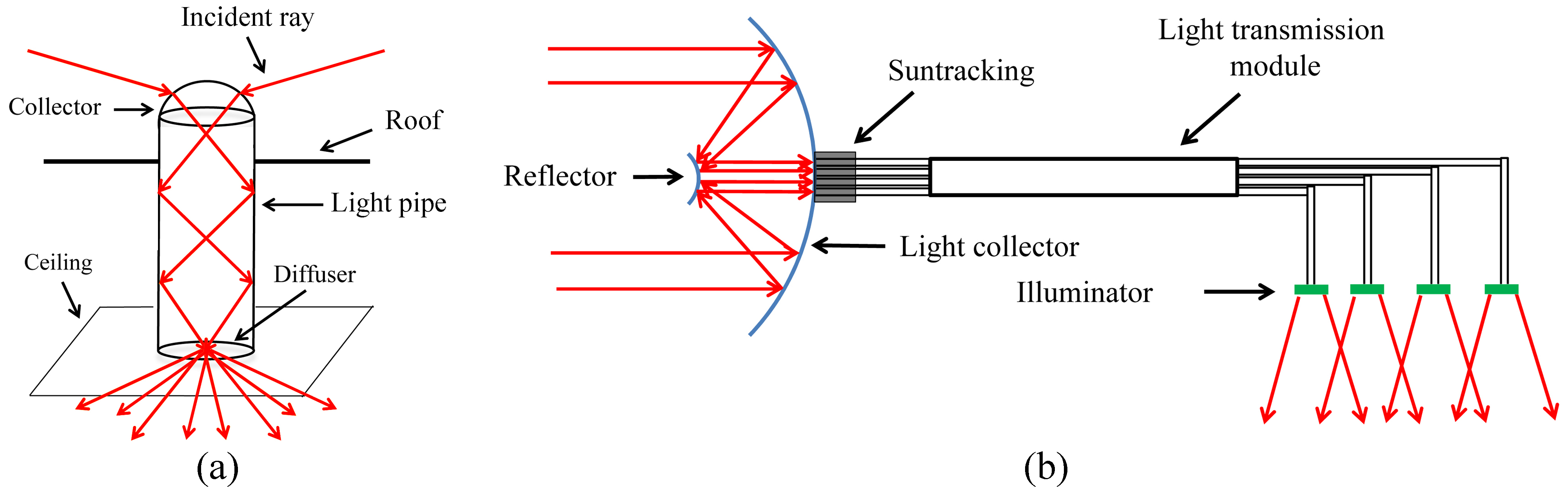
Fig. 1. (a) Schematic representation of a light pipe daylighting system and (b) 2D schematic drawing of a optical fiber daylighting system consisting of collector, transmission, and illuminator modules.
Daylighting system should be simple and cost-effective to follow the need of the market. The simplest method to deliver daylight to each floor of the multi-floor building has been demonstrated using lightwell where light is transported in the free space without any light transportation media [9]. It was found that the top three floors received sufficient daylight showing daylight factors (DFs) greater than 2% while DFs for lower three floors were lower than the recommended value of 2%. Fiber-based daylighting systems used plastic optical fiber and glass optical fiber to transmit daylight at deep inside the building [10-12]. To increase light illuminance, a concentrator, such as parabolic reflector or Fresnel lens, was used that transmited high intensity light into the fiber. A comparison analysis of different fiber based daylighting systems was presented in [13,14]. In [15], performance of two daylighting systems using optical fiber and light pipe were compared. A transparent dome cover was used at the inlet of light pipe where a greater number of lumens was available at a higher solar altitude. Further, using a tracking solar dish, more daylight was harvested than that of light pipe for solar altitudes of less than 50 degrees. It was concluded that illuminance uniformity ratio varies more in light pipe system than fiber system.
Electric lighting energy was reduced in farm animal production using daylight transmission through light pipe [16,17]. Light pipe designs gave better results with a tilt angle of 6 degree, which was achieved through simulation [18]. HOLIGILM tools was used to check performance of different light pipes in different climate zones [19]. Light well was used to transmit daylight to attached rooms where performance of different sizes of light well was investigated [20]. In [21], a heliostat was used to capture and redirect the light into the light pipe, which was made of prismatic film, through Fresnel lens and reflectors. A study was conducted to provide equal amount of light at each floor of a multilevel building using vertical light pipe [22]. Experimental analysis of a light pipe supporting side apertures to illuminate multi-levels of a building was conducted where an average illuminance of 80 lux and 532 lux was achieved [23]. It was concluded through experiments that light pipe enhanced daylight levels in the indoor providing significant variations due to incident sunlight angles. Further, different active and passive components have been used to enhance performance of daylighting systems [24,25]. Core sunlighting system has been commercialised providing daylight to illuminate core of a building using active and passive components at the inlet side and light guide for light transmission and distribution [26]. To meet the illuminance standards, light control is essential to provide the required light levels.
This research presents the optical raytracing simulation of the proposed daylighting design using LightTools® optical-simulation tools [27-30]. Mechanical and optical components are designed, analysed, and verified. Light losses due to mechanical and optical components are also considered calculating efficiency of the system. Objective of this study is to provide daylight at multi levels of a building. To achieve the objective, heliostats are used to capture the light and increased concentration level and then light pipe transported the light to each floor. Both heliostats and light pipe make the system cost-effective than that of parabolic reflector and optical fiber based systems [13]. Light is distributed at each floor through the prismatic light guide. The proposed system guarantees to deliver sunlight deep into the core of the multi-floor building. Further, this research improves efficiency of the light pipe-based daylighting system.
2. Light collector
Daylighting systems are integrated with buildings that result energy saving and provide high quality illumination. A daylighting system collects sunlight through mirrors and lenses and transmits the light inside the core of the building providing illumination and visual comfort. Various collectors have been presented in the literature, such as parabolic mirror, Fresnel lens, etc. All these active concentrator-based systems needed perfect optics and a precise sun-tracking to achieve high efficiency.
Light collector included heliostats having two-axis sun-tracking and a flat circular mirror. Heliostats were made of circular flat mirrors that reflected the incident light toward a central flat mirror placed at upstream of light pipe that reflected the light inside the light pipe. Due to reflections inside the light pipe, light was transmitted to multi-levels of the building. A redirecting mirror at the ceiling of each floor inserted the light into the light guide, which distributes the light uniformly. Block diagram of the proposed heliostats daylighting system presenting flow of simulation is shown in Fig. 2.
Figure 2
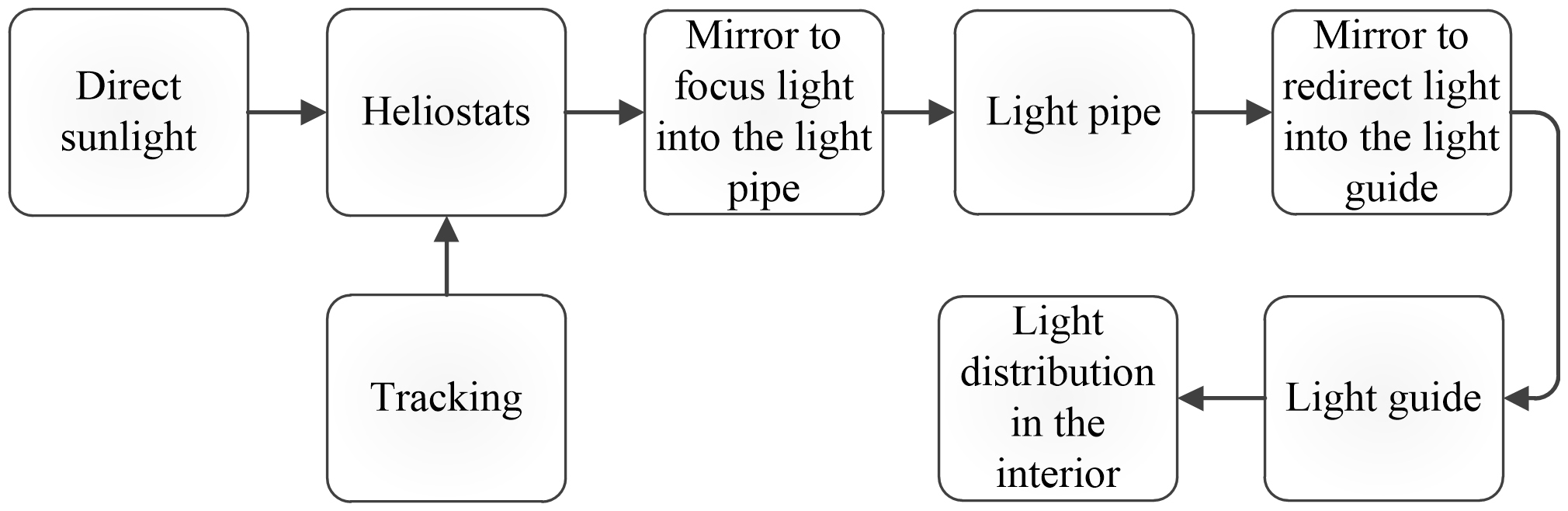
Fig. 2. Flow chart of the heliostat-based daylighting system.
Circular flat mirror was placed at the center, upstream of the light pipe, while heliostats were mounted in four different circles of radii r1, r2, r3, and r4, as shown in Fig. 3. While arranging heliostats, it was considered to minimize the shadow due to neighboring heliostats. The circular flat mirror was tilted 10.12° with respect to the ground axis for inserting maximum concentrated light into the light pipe. To illuminate an area of 5×50 m2, area of five floors, fourteen heliostats were used. The length of the light pipe was 19.9 m to illuminate five floors of the building. Diameters of the circular flat mirror and heliostat were 1 m and 0.7 m, respectively (Table 1). In Fig. 3, α and β are the line angles with respect to ground axis where heliostats were placed in different circles. Each heliostat had a sun tracking module to reflect the incident light towards the circular flat mirror at all daylight hours.
Figure 3
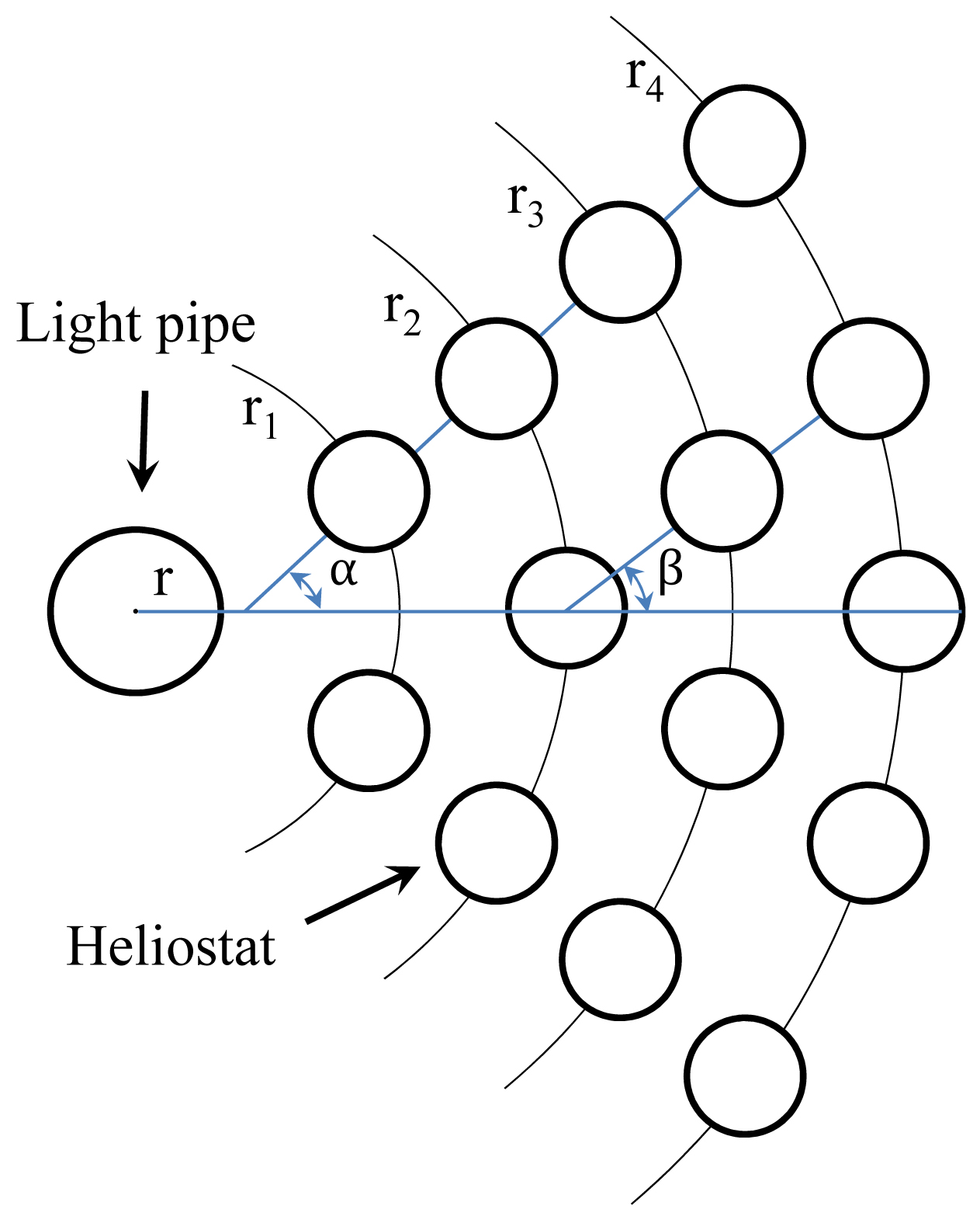
Fig. 3. Representing arrangement of heliostats and the light pipe in different arcs of radii r1,r2, r3, r4.
Table 1
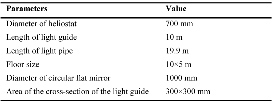
Table 1. Designing parameters of different modules.
The maximum concentrated light was inserted into the light pipe by
where Dl is the diameter of the light pipe and Df is the diameter of the flat circular mirror. The optical transmittance of the light pipe can be calculated by [31]
where R is the reflectivity of the light pipe, l is the length of the light pipe, θ is the angle of incidence of the illuminating radiation with respect to the axis of the light pipe, and deff is the effective diameter.
3. Light guide for indoor illumination
Uniform light distribution has been an important consideration in different light applications. In this study, a light guide was used to distribute the light in the interior. A prismatic optical lighting film and multilayer optical film were used to develop the light guide, as shown in Fig. 4 [32]. Optical lighting film had a thickness of 0.508 mm and transmittance and reflection of 99% [33]. Multilayer optical film had a reflection of 97% [34]. The purpose of using this light guide was to illuminate core region of the building with uniform illumination levels. Minimum floor-to-floor height of 3 m with a ceiling height of 2.4 m and 4-4.2 m has been used in different countries, such as USA and Asian countries [35,36]. In this study, a standard 4 m floor-to-floor height and a ceiling height of 2.74 m was used, as shown in Fig. 5.
Figure 4
![(a) Schematic detailing the geometry of the prismatic light film used in the light guide to transport and distribute the light [32-34] and (b) the redirecting mirror.](figures/6-202-4.jpg)
Fig. 4. (a) Schematic detailing the geometry of the prismatic light film used in the light guide to transport and distribute the light [32-34] and (b) the redirecting mirror.
Figure 5
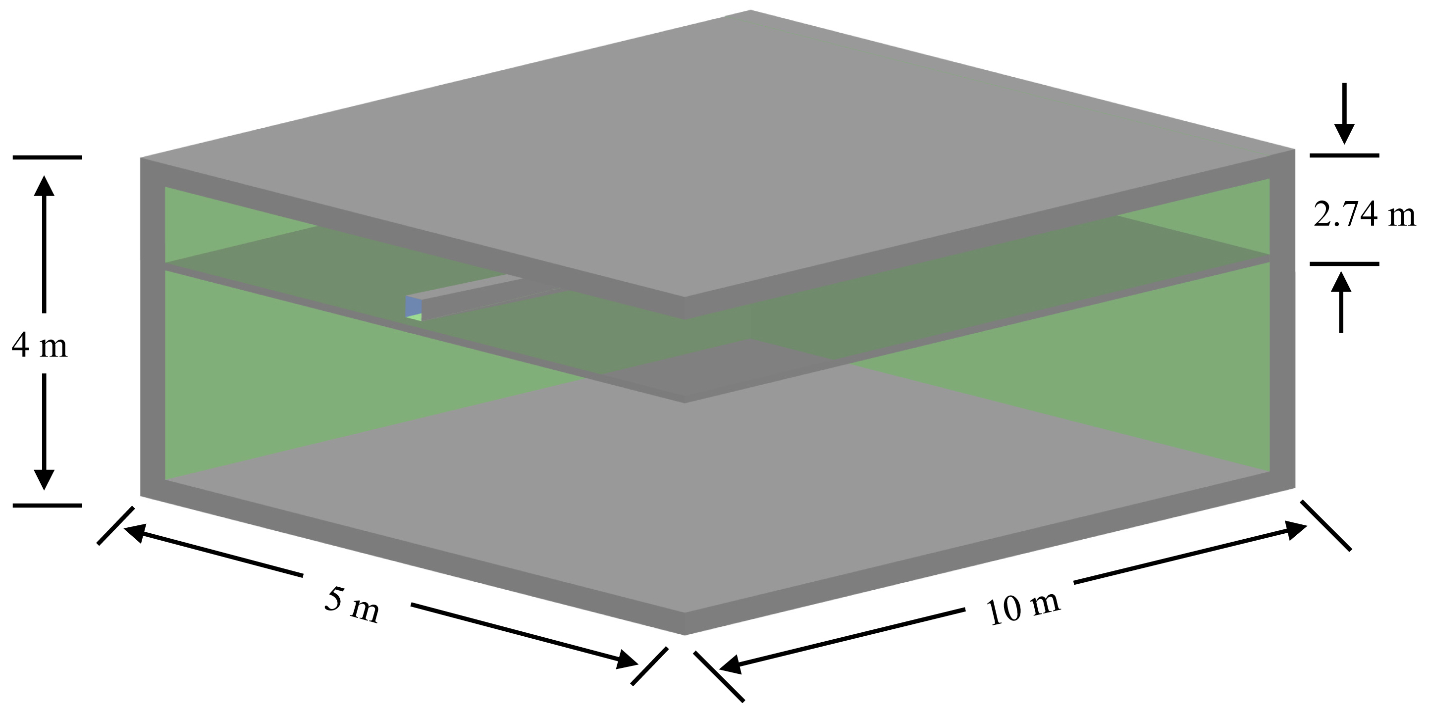
Fig. 5. Schematic showing floor dimensions.
4. Simulation
The system was designed for the site located at a latitude of 31.5° and a longitude of 74.3°, Lahore, Pakistan. The outdoor illuminance was measured at different daylight hours using Lux meter [38] (Fig. 6) on May 30, 2019. The measured illuminance values were rounded off for using them in simulation software and calculating lumens, as shown in Table 2. Outdoor illuminance at 9 am, 10 am, and 11 am were almost similar to illuminance at 3 pm, 2 pm, and 1 pm, respectively.
Figure 6
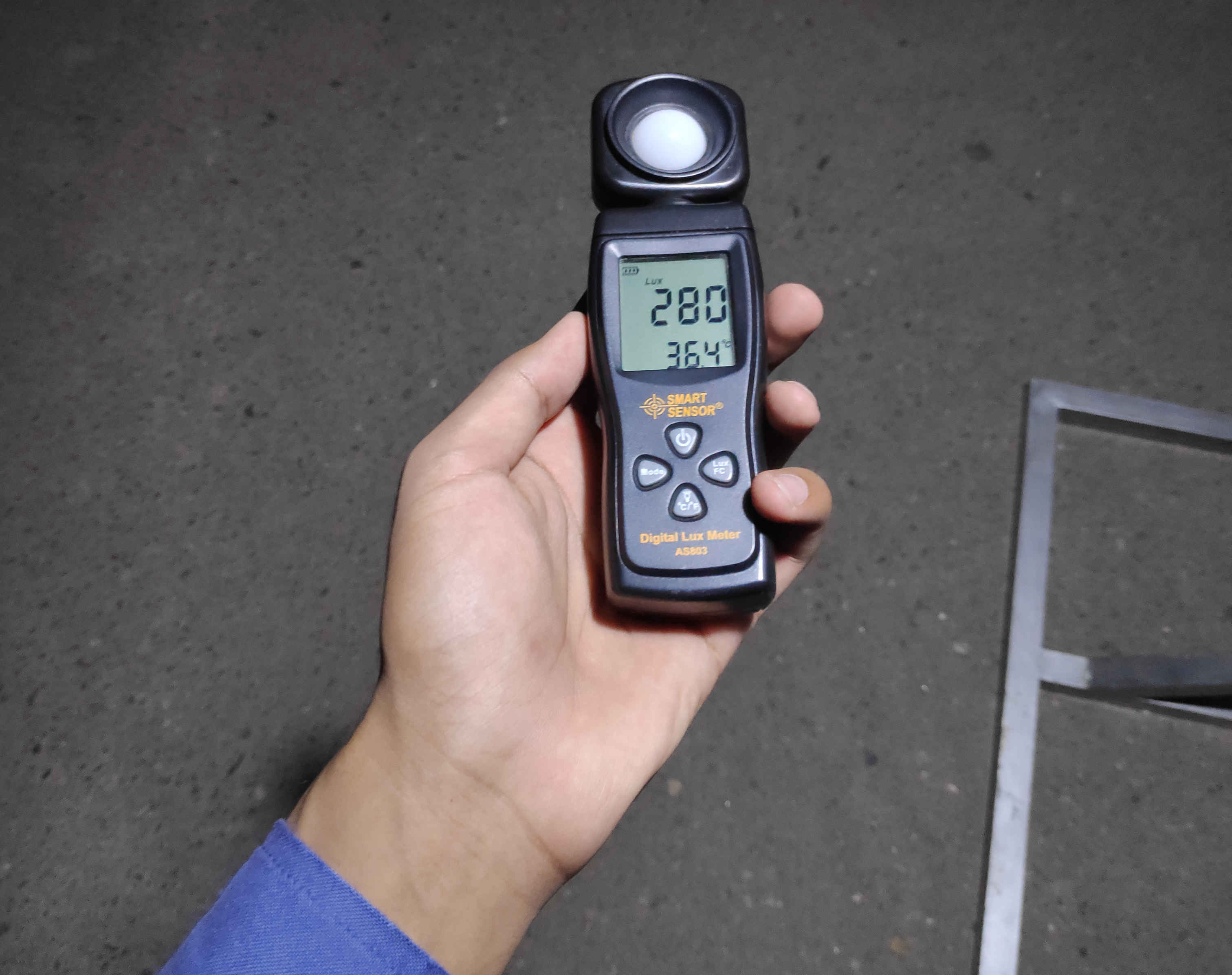
Fig. 6. Lux meter for measuring outdoor illuminance.
Table 2
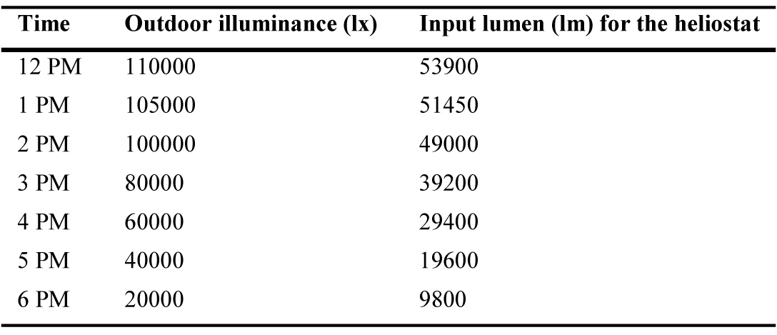
Table 2. Outdoor illuminance at different times of the day.
Simulation was performed in LightTools® optical-simulation software. For real implementation, heliostats achieved direct light using sun-tracking while a collimated light source was designed in the simulation to get collimated light. First, the outdoor illuminance was measured and lumens were calculated to simulate the optical system by [37]
where E is the measured illuminance, dF is the input luminous flux in lumens, and dS is the area of the concentrator. All the optical modules, such as heliostats, central mirror, light pipe, prismatic film, and optical light film were designed and verified using raytracing simulation. Transmittance and reflection of all optical modules were set in the simulation to get realistic results. All losses were considered in the simulation to analyse the performance of all optical modules. For the raytracing simulation, 0.2 million rays were set as the input parameter. The light transmission efficiency of the light pipe can be calculated as [18]
5. Results
A raytracing diagram representing how the light was collected and inserted into the light pipe is shown in Fig. 7(a). The main purpose was to insert maximum concentrated light into the light pipe. For this purpose, diameter of the heliostat was kept smaller than the diameter of the flat circular mirror, which received rays from heliostats. An example presenting lost rays because of sun-tracking error is shown in Fig. 7(b). Since an independent sun-tracking module is installed with each heliostat, if a sun-tracking error occurs, most of the rays are lost. Illuminance at the inlet of the light pipe illustrating uniform distribution is shown in Fig. 8. Because of uniform illuminance inside the light pipe, it was easier to redirect the light to each floor. High illuminance was achieved because the light was concentrated from fourteen heliostats. Illuminance level could be increased or decreased by increasing or decreasing the heliostats, respectively.
Figure 7
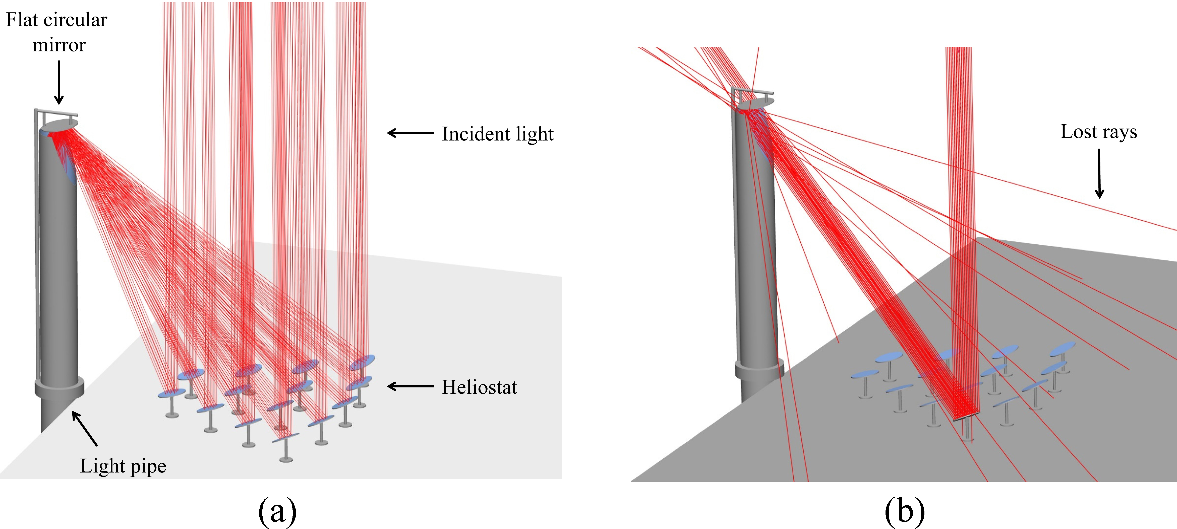
Fig. 7. (a) Raytracing diagram of the daylighting system showing fourteen heliostats, comprising sun tracking to get collimated light, focusing light towards circular flat mirror. The light is then reflected into the light pipe, which transmits light to multi floors of the building. (b) Showing lost rays because of suntracking error.
Figure 8
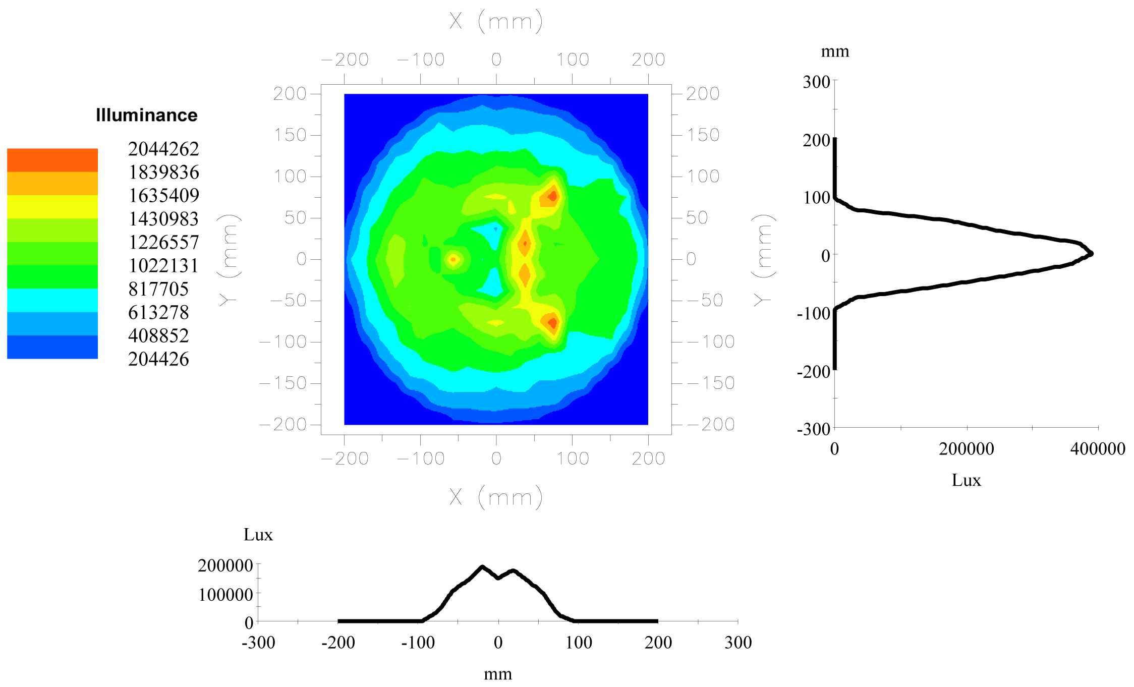
Fig. 8. Showing illuminance at the inlet of the light pipe.
Raytracing for single-story building is shown in Fig. 9. Here, all the light was transmitted to the single floor. High illuminance was achieved because of small length of light pipe and small distribution area compared to the multi-floor building. A bent light pipe was used to transmit all the light towards light guide for distribution. It should be noted that light redirecting mirror inside the light pipe was not used for single floor building. 3D view of multi-floor building comprising daylighting system is shown in Fig. 10(a). Raytracing for the multi-floor building is performed to check illuminance levels at different floors, as shown in Fig. 10(b).
Figure 9
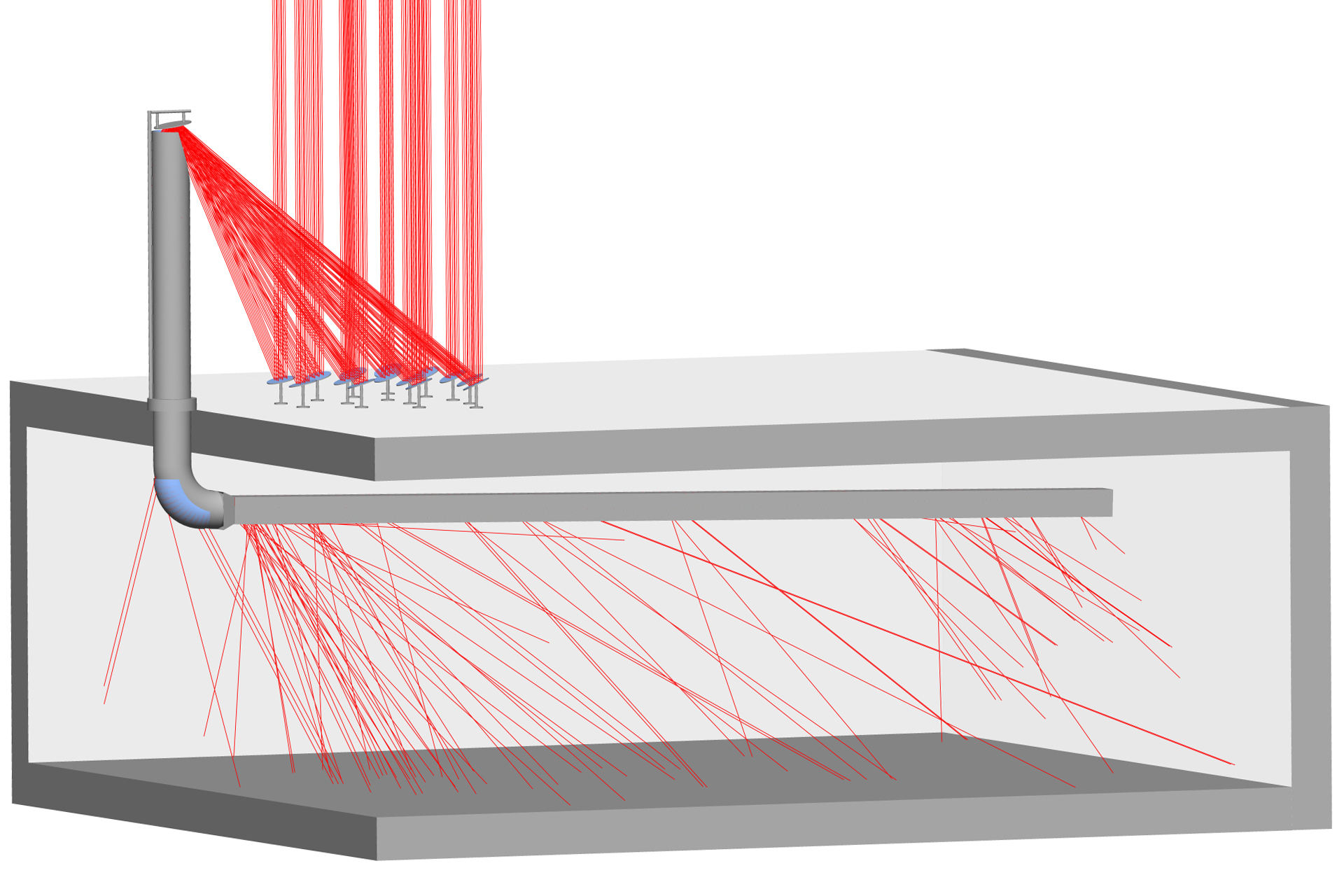
Fig. 9. Ray tracing of heliostats design for single story building showing rays distribution in the interior.
Figure 10
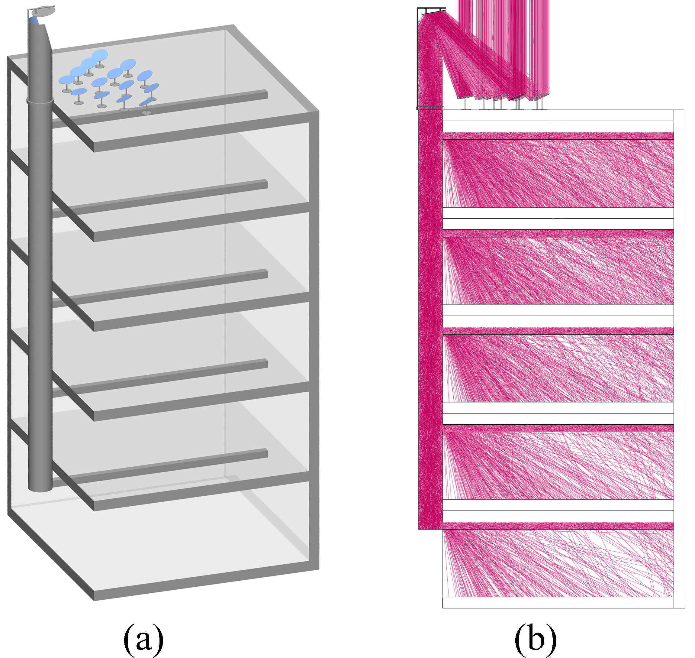
Fig. 10. (a) 3D view of the heliostats design for multi-floor building and (b) raytracing showing light distribution at different floors of the multi-floor building.
The Illuminance distribution at top floor was measured at different daylight hours, and an average illuminance of 930 lx was achieved at 12 pm, as shown in Fig. 11. It could be seen that nearly uniform illuminance level was achieved. Similarly, simulations were conducted to measure illuminance levels at different times of the day for all floors, as shown in Fig. 12. High average illuminance was achieved at top floor while lower floors achieved less illuminance.
Figure 11
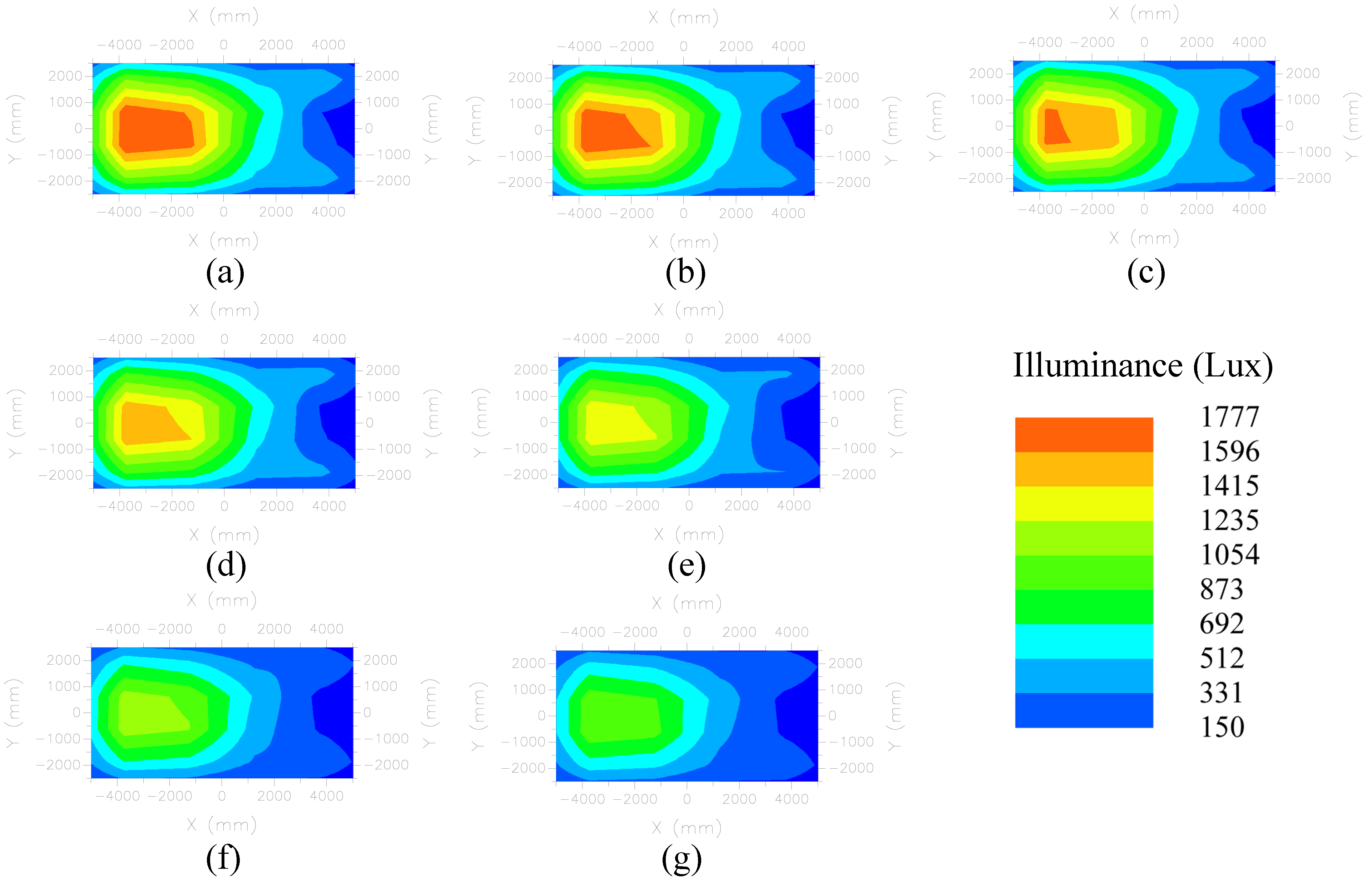
Fig. 11. Illuminance distribution on the top floor of the multi-floor building at (a) 12 pm, (b) 1 pm, (c) 2 pm, (d) 3 pm, (e) 4 pm, (f) 5 pm, and (g) 6pm.
Figure 12
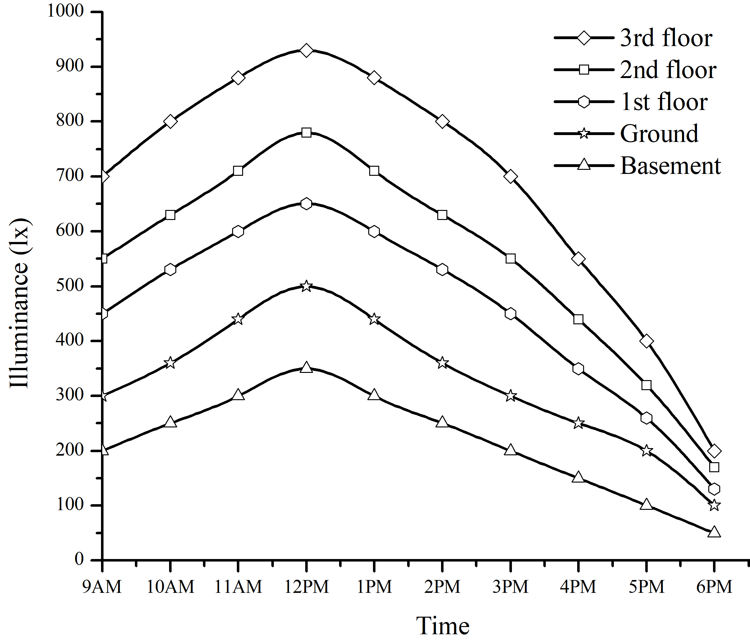
Fig. 12. Average illuminance on different floors of the multi-floor building.
6. Discussion
In the proposed design, number of heliostats were fixed; however, for getting higher illuminance levels on all floors, heliostats could be increased. The arrangement and size of both the circular flat mirror and the light pipe will be changed. A flat redirecting mirror was used to transmit the light into the light guide. For uniform light transmission to all floors, the design of redirecting mirror should be improved. The illuminance was decreased if number of floors are increased because of high losses of the light pipe and simple design of the redirecting mirror.
In the simulation, reflection of walls and floor are not considered. The light distribution included the light that hit the floor from the light source (light guide); however, the results will be improved by considering reflection parameters of walls and floor.
Since large number of heliostats were not used in the literature, simulations of the proposed design were conducted for presenting results of the initial phase. Further improvements will be performed and presented in the near future.
7. Conclusions
The primary focus of this research was to illuminate the interior of a multi-floor building during daylight hours. For this purpose, heliostats were used to capture and concentrate the sunlight for delivering it to five floors of the building. A light pipe was used for transmitting the light to all floors. Both the heliostats and the light pipe made the daylighting system cost-effective. A light guide was designed using reflective ad prismatic films for distributing the light in the interior of the building. Raytracing simulation was performed for calculating the efficiency and evaluating the system. In the simulation, a collimated light source illuminated heliostats that reflected the light towards the flat mirror where the light was concentrated and reflected inside the light pipe, which transmitted the light to all floors. A redirecting mirror at the inlet of the light guide inserted the light into the light guide. Illuminance distribution on the floor was shown and it was found that five floors of the building were illuminated with different illumination levels. An average illuminance of 930 lux was achieved on the top floor at 12 pm. The illuminance value was decreased as the distance of light pipe increased. It was found that an efficiency of 40% was achieved with almost uniform illumination in the interior. It was observed that the illuminance on the floor decreased as the length of the light guide increased, and higher illuminance was observed near the inlet side.
References
- M. Stiles, R. Mccluney, and L. Kinney, Solar Lighting-A New Industry, Light and Engineering 6 (1998) 1-13.
- U.S. Green Building Council. Green Building Rating Systems—Draft Recommendations for a U.S. Rating System. Bethesda, Md.: U.S. Green Building Council, 1995.
- P. E. Kristensen, Daylighting Technologies In Non-Domestic Buildings, Int. J. Solar Energy 15 (1994) 55-67. https://doi.org/10.1080/01425919408909822
- A. Rosemann, G. Cox, P. Friedel, M. Mossman, and L. Whitehead, Cost-effective controlled illumination using daylighting and electric lighting in a dual-function prism light guide, Lighting Research and Technology 40 (2008) 77-88. https://doi.org/10.1177/1477153507083905
- I. Ullah, Optical Modeling of Two-stage Concentrator Photovoltaic System Using Parabolic Trough, Journal of Photonics for Energy 9 (2019) 043102. https://doi.org/10.1117/1.jpe.9.043102
- J. T. Kim, G. Kim, Overview and new developments in optical daylighting systems for building a healthy indoor environment, Building and Environment 45 (2010) 256-269. https://doi.org/10.1016/j.buildenv.2009.08.024
- J. Song, Z. Jin, Y. Zhu, Z. Zhou, Y. Yang, Development of a fiber daylighting system based on the parallel mechanism and direct focus detection, Solar Energy 115 (2015) 484-493. https://doi.org/10.1016/j.solener.2015.03.022
- MG Nair, K Ramamurthy, and AR Ganesan, Classification of indoor daylight enhancement systems, Lighting Res. Technol. 46 (2014) 245–267. https://doi.org/10.1177/1477153513483299
- Y. Su, H. Han, S. B. Riffat, and N. Patel, Evaluation of a lightwell design for multi-storey buildings, Int. J. Energy Res. 34 (2010) 387-392. https://doi.org/10.1002/er.1651
- V.E. Gilmore, Sun Flower Over Tokyo, Popular Science, Bonnier Corporation, USA, 747 1988.
- D. Feuermann, J.M. Gordon, Solar fiber-optic mini-dishes: a new approach to the efficient collection of sunlight, Solar Energy 65 (1999) 159–170. https://doi.org/10.1016/s0038-092x(98)00129-7
- I. Ullah and S. Shin, Highly Concentrated Optical Fiber-Based Daylighting Systems for Multi-Floor Office Buildings, Energy and Buildings 72 (2014) 246-261. https://doi.org/10.1016/j.enbuild.2013.12.031
- I. Ullah and A. J.-W. Whang, Development of Optical Fiber-Based Daylighting System and Its Comparison, Energies 8 (2015) 7185–7201. https://doi.org/10.3390/en8077185
- I. Ullah, H. Lv, A. J.-W. Whang, and Y. Su, Analysis of a novel design of uniformly illumination for Fresnel lens-based optical fiber daylighting system, Energy and Buildings 154 (2017) 19–29. https://doi.org/10.1016/j.enbuild.2017.08.066
- S. J. Oh, W. Chun, S. B. Riffat, Y. I. Jeon, S. Dutton, and H. J. Han, Computational analysis on the enhancement of daylight penetration into dimly lit spaces: Light tube vs. fiber optic dish concentrator, Building and Environment 59 (2013) 261–274. https://doi.org/10.1016/j.buildenv.2012.08.025
- H. v. Wachenfelt, V. Vakouli, A. P. Diéguez’, N. Gentile, M.-C. Dubois, and K.-H. Jeppsson, Lighting Energy Saving with Light Pipe in Farm Animal Production, Journal of Daylighting 2 (2015) 21-31. http://dx.doi.org/10.15627/jd.2015.5
- A. P. Diéguez’, N. Gentile, H. v. Wachenfelt, and M.-C. Duboisba, Daylight Utilization with Light Pipe in Farm Animal Production: A Simulation Approach, Journal of Daylighting 3 (2016) 1-11. http://dx.doi.org/10.15627/jd.2016.1
- L. Sharma, S. F. Ali, and D. Rakshit, Performance evaluation of a top lighting light-pipe in buildings and estimating energy saving potential, Energy and Buildings 179 (2018) 57–72. https://doi.org/10.1016/j.enbuild.2018.09.022
- E. K. W. Tsang, M. Kocifaj, D. H. W. Li, F. Kundracik, and J. Mohelníková, Straight light pipes’ daylighting: A case study for different climatic zones, Solar Energy 170 (2018) 56–63. https://doi.org/10.1016/j.solener.2018.05.042
- A. A. Ahadi, M. R. Saghafi, and M. Tahbaz, The study of effective factors in daylight performance of light-wells with dynamic daylight metrics in residential buildings, Solar Energy 155 (2017) 679–697. https://doi.org/10.1016/j.solener.2017.07.005
- A. Rosemann , H. Kaase, Lightpipe applications for daylighting systems, Solar Energy 78 (2005) 772–780. https://doi.org/10.1016/j.solener.2004.09.002
- V. Garcia-Hansen, I. Edmonds, Methods for the illumination of multilevel buildings with vertical light pipes, Solar Energy 117 (2015) 74–88. https://doi.org/10.1016/j.solener.2015.04.017
- D. M. Kennedy and F. O’Rourke, Experimental analysis of a scaled, multi-aperture, light-pipe, daylighting system, Solar Energy 122 (2015) 181–190. https://doi.org/10.1016/j.solener.2015.08.013
- N. O. Onubogu, K.-K. Chong, C.-W. Wong, T.-K. Yew, B.-H. Lim, Optical characterization of two-stage non-imaging solar concentrator for active daylighting system, Solar Energy 185 (2019) 24-33. https://doi.org/10.1016/j.solener.2019.04.028
- M.S. Mayhoub, Fifty years of building core sunlighting systems – Eight lessons learned, Solar Energy 184 (2019) 440-453. https://doi.org/10.1016/j.solener.2019.03.097
- S. Khosravi, M. A. Mossman, L. A. Whitehead, Core Sunlighting System, a New Approach to Daylighting in Buildings, Energy Procedia 57 (2014) 1951-1960. https://doi.org/10.1016/j.egypro.2014.10.059
- C. Tsuei, W. Sun, C. Kue, Hybrid sunlight/LED illumination and renewable solar energy saving concepts for indoor lighting, Optics Express 18 (2010) A640–A653. https://doi.org/10.1364/oe.18.00a640
- C. E. Ochoa, M. B. C. Aries, J. L. M. Hensen, State of the art in lighting simulation for building science: a literature review, Journal of Building Performance Simulation 5 (2012) 209–233. https://doi.org/10.1080/19401493.2011.558211
- B-J. Chen, B.-Y. Gao, I. Ullah, K.-Y. Chen, C.-H. Chou, C.-M. Lin, C.-M. Chang, K.-C. Jhan, A. J. Whang, Freeform Microstructure Linear Light Emitter Design for Nature Light Illumination System, Applied Optics 54 (2015) E159-E164. https://doi.org/10.1364/ao.54.00e159
- B. Obradovic, B. S. Matusiak, Daylight Transport Systems for Buildings at High Latitudes, Journal of Daylighting 6 (2019) 60-79. http://dx.doi.org/10.15627/jd.2019.8
- P. D. Swift and G. B. Smith, Cylindrical mirror light pipes, Solar Energy Materials and Solar Cells 36 (1995)159-168. https://doi.org/10.1016/0927-0248(94)00172-3
- A. Rosemann, M. Mossman, and L. Whitehead, Development of a cost-effective solar illumination system to bring natural light into the building core, Solar Energy 82 (2008) 302-310. https://doi.org/10.1016/j.solener.2007.09.003
- Optical Lighting FilmTM, Product No. 2301, from 3M Company, St. Paul, MN, USA, 55144-1000, 1988.
- Visible Mirror 2000TM, Product No. VM 2000, from 3M Company, St. Paul, MN, USA, 55144-1000, 2000.
- J. Cho and K. R. Chung, Country Report: South Korea, CTBUH Journal 4 (2011) 42-47.
- A. E. Kohn and P. Katz, Office Buildings, John Wiley & Sons, New York, USA, 2002.
- V. N. Mahajan, Optical Imaging and Aberrations, Part 1: Ray Geometrical Optics, SPIE Press, Washington, USA, 1998.
- AS803 Lux meter, Smart Sensor®, China.
Copyright © 2019 The Author(s). Published by solarlits.com.

6437
Total views
Citations
SHARE ON


