Article Outline
Figures and tables
Volume 6 Issue 2 > pp. 52-59 • doi: 10.15627/jd.2019.7
Application of Micro-structured Sunlighting Systems in Different Climatic Zones
Helmut F.O. Mueller*
Author affiliations
Green Building R&D GmbH, Duesseldorf, Germany
* Corresponding author.
helmut.mueller@greenbuildig-rd.com (H. F.O. Mueller)
History: Received 19 July 2019 | Revised 27 August 2019 | Accepted 29 August 2019 | Published online 4 September 2019
Copyright: © 2019 The Author(s). Published by solarlits.com. This is an open access article under the CC BY license (http://creativecommons.org/licenses/by/4.0/).
Citation: Helmut F.O. Mueller, Application of Micro-structured Sunlighting Systems in Different Climatic Zones , Journal of Daylighting 6 (2019) 52-59 http://dx.doi.org/10.15627/jd.2019.7
Figures and tables
Abstract
Two-sided micro-structures on windowpanes have been developed for redirecting sunlight into the depth of rooms in order to improve daylighting. In a joint research project comprehensive sunlighting-systems for windows are developed, integrating micro-structures in triple-glass units. The fixed units redirect sunlight to the ceiling and the depth of the room, avoiding glare. The system works for all solar altitudes and therefore can be applied in locations of all latitudes and climate zones. The study compares the energy efficiency of the sunlighting system in different locations. The performance of the sunlighting system has been simulated by tools like DiaLux and tested by measurements. Based on these validated data, a simplified design tool for early design stages is developed. It uses sun-path diagrams to define the annual hours of direct sunlight on windows in the main orientations (N, E, S, and W). This theoretical figure is corrected by the realistic percentage of sunshine hours taking into account the annual time of covered sky of typical climatic regions. Resulting actual hours of insolation (and light redirection) for the main window orientations are defined for a variation of latitudes and climates. Examples of typical office rooms located in latitudes between 0° and 60° and climates with varying cloudiness are used to demonstrate the sunlighting potential. The annual hours of sufficient lighting under clear sky conditions range between 700 and 1900. Resulting savings in lighting energy allow for the return of an investment of 50 to 100 €/m² glazing within 2 years for certain assumptions. The additional costs for the light redirecting micro-structures in the glass are not likely to exceed this range.
Keywords
Climatic zone, Lighting energy, Microstructure, Sunlight redirection
1. Introduction
Consumption of electrical energy for room lighting can be reduced by daylighting systems redirecting direct sunlight to a reflective ceiling and the depth of the room [1-9]. Artificial light can be dimmed or switched off for large room areas during periods of insolation on windows, while solar heat gains and glare are avoided [10,11]. No direct glare can occur as the micro-structured components for sunlight redirection are fixed in the upper window area above eye level (Fig. 1). A solar protective coating on the glass unit reflects the infrared spectrum and transmits only the visible spectrum in a selective manner [12]. Because of the micro-structure, the light redirecting glass unit in the upper window area cannot be looked through in contrast to the lower window area. For the lower part of the window, any kind of conventional solar protection can be applied, like shading systems or solar protective glazing.
Figure 1
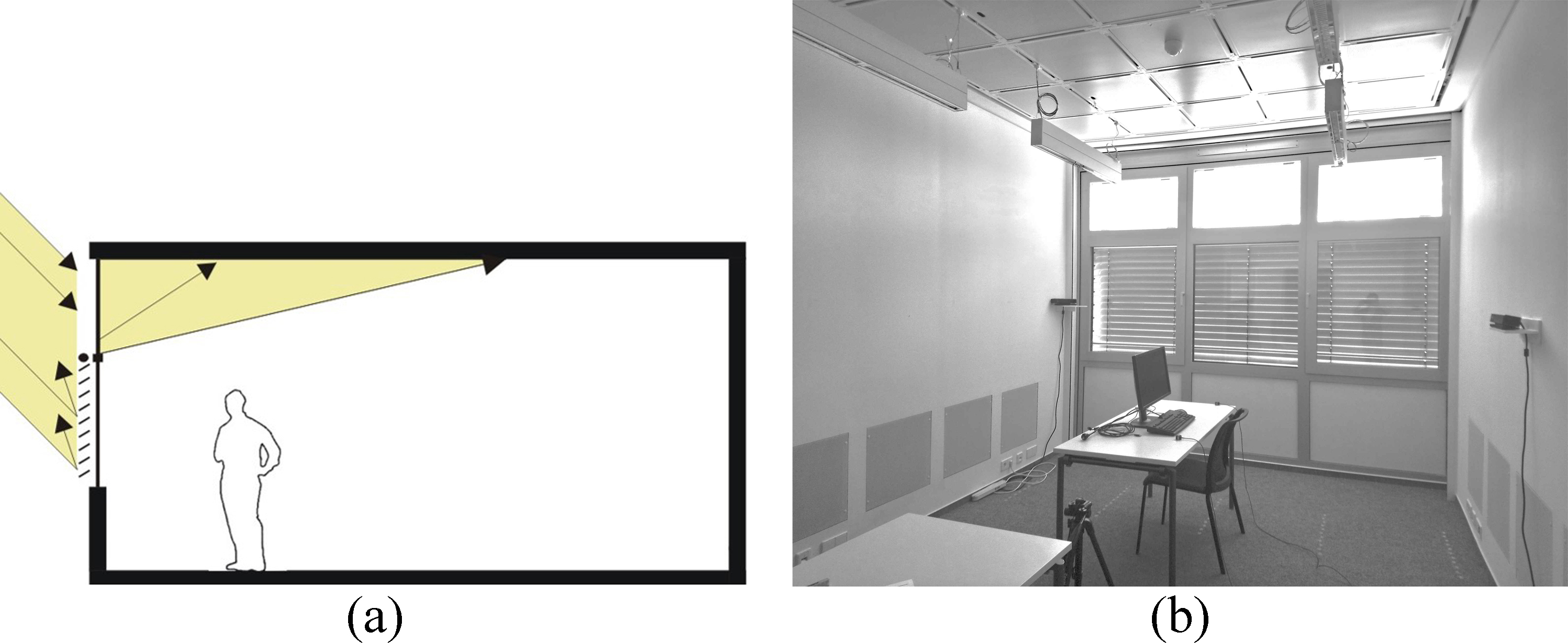
Fig. 1. (a) Principle of redirecting solar light from the upper window area to a reflecting ceiling and deep into the room. Solar protection in the lower window area, e.g. shading or glass coating. (b) Prototypes in test-room of Fraunhofer IBP, Stuttgart.
Prototypes of these micro-structured window components have been manufactured, measured, and monitored under natural conditions in test rooms of the Fraunhofer IBP in Stuttgart, Germany [12].
The vertical redirection of sunlight, which works without tracking for a large range of solar altitudes, is integrated as a pane with microstructures on both surfaces in the centre of a triple glass unit. It is protected against deposit of dust and physical impact in the gap between the outer panes (Fig. 2). In order to avoid hard contrasts of illuminance the vertically redirected sunlight is spread horizontally by a structure on the inner surface of the glass unit (surface 6).
Figure 2
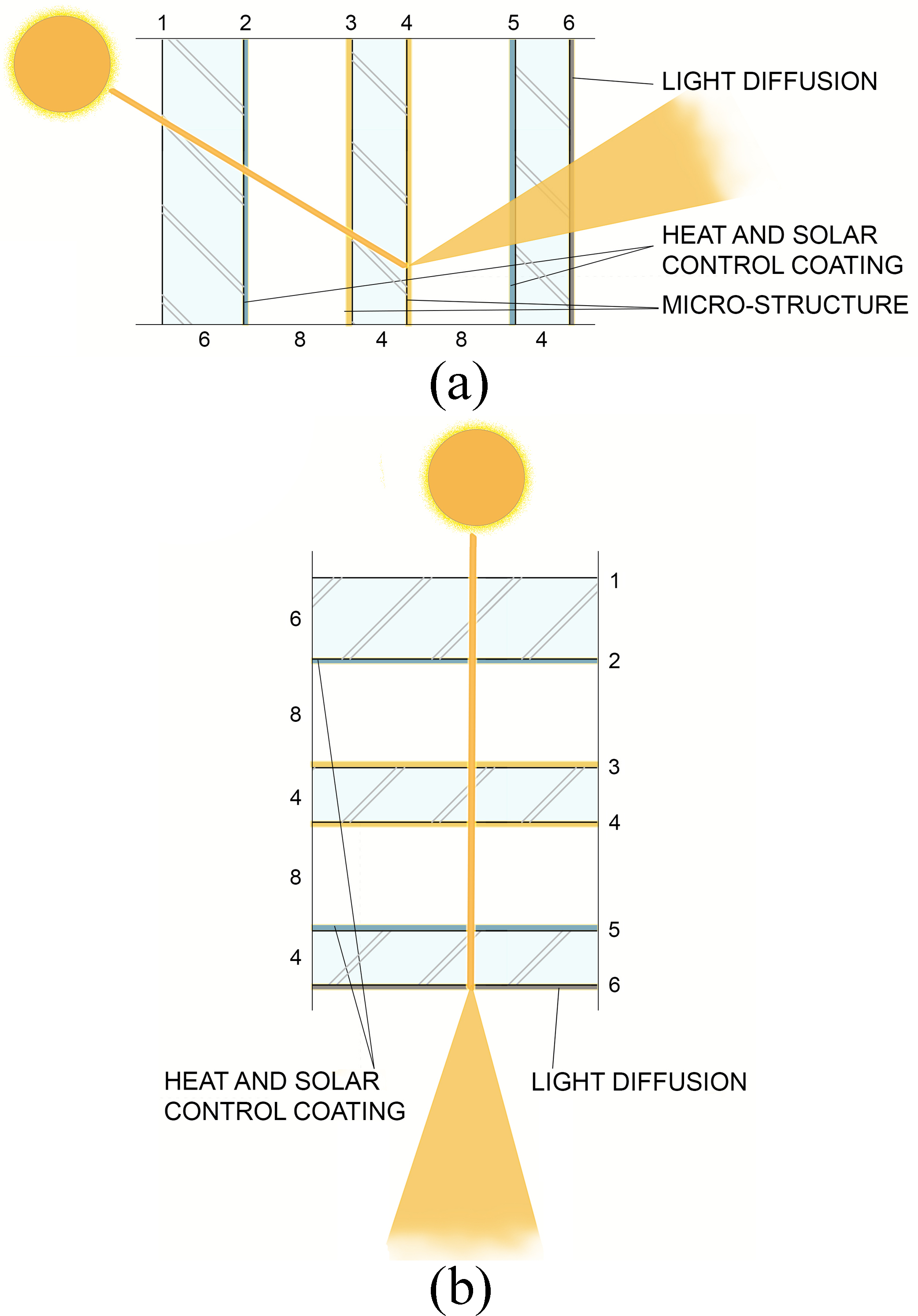
Fig. 2. (a) and (b) Integration of redirecting structures in triple glass unit. Vertical redirection by micro-structures on surface 3 and 4. Horizontal light spreading by a structure on surface 6.
The vertical redirection, consisting of a 3 mm thick acrylic or glass plate with a microstructure on each surface, is shown in Fig. 3. Facing the sun there are micro lenses focusing the sunlight inside the plate and spreading the light rays vertically over a wide angular range. On the opposite surface prisms, redirect the light to the ceiling by total inner reflection and refraction.
Figure 3
![(a) Vertical section with function principle of vertical sunlight redirecting pane with micro-structures on both surfaces [12]. (b) Horizontal section with horizontal spreading of light by sinusoidal structure of glass pane (surface 6).](figures/6-52-3.jpg)
Fig. 3. (a) Vertical section with function principle of vertical sunlight redirecting pane with micro-structures on both surfaces [12]. (b) Horizontal section with horizontal spreading of light by sinusoidal structure of glass pane (surface 6).
The horizontal spreading of light is caused by the room-facing sinusoidal structure (surface 6) of the glass pane (Fig. 3). It was developed and manufactured for this purpose by the glass partner of the research consortium [12,13].
Depending on the task (location, window orientation, and resulting solar altitude) as well as the manufacturing technology of micro-structures, different solutions have been developed for the vertical redirection. Hot-embossing and UV-embossing of PMMA has been applied by the partners of the research consortium [12] in order to achieve a variety of solutions. The objective was to develop micro-structures for a maximum range of solar altitudes, which can be applied in many different geographic latitudes and in different climates, from temperate to tropical. Figure 4 shows simulated results of the optimization process with high efficiencies for sunlight redirection for solar heights from 15° to 70°. As the light reflection at the glass surface is increasing with the angle of incidence, a tilted sunligting component will improve the efficiency for solar altitudes >70° (Fig. 5). If solar altitudes <15° can cause glare, e.g. in high-rise buildings, suitable measures for glare avoidance will be applied.
Figure 4
![Optimization of sunlight redirection. Relative transmission of sunlight to the ceiling and to the floor over angle of incidence, i.e. solar altitude [12].](figures/6-52-4.jpg)
Fig. 4. Optimization of sunlight redirection. Relative transmission of sunlight to the ceiling and to the floor over angle of incidence, i.e. solar altitude [12].
Figure 5
![Tilted sunlighting component improves light redirection for solar altitude > 70° [13].](figures/6-52-5.jpg)
Fig. 5. Tilted sunlighting component improves light redirection for solar altitude > 70° [13].
The magnitude of energy savings by sunlighting in different geographic latitudes is a crucial requirement for the early building design phases. According to the new European Energy Perfomance in Buildings Directive (EPBD 2018/844) [14], daylight must be considered. Moreover, the new international standard for daylighting, CEN EN 17037, Daylight of Buildings [15], defines recommendations of daylight provision as well as calculation methods of their assessment. Target illuminances of 300, 500, and 750 lx can be calculated by validated software for Daylight factors [16,17] or for illuminance levels using climate data for a given site and an adequate time step [18-20]. As the Daylight factor is based on covered sky conditions, the method using climate data is applied for daylighting by direct sunlight (clear sky conditions).
There are several simulation tools available for this task, like RADIANCE, TRNSYS, RELUX, and DiaLux, the last of which was used in this project to calculate the daylight provision for varying architectural designs, locations, and time steps. This dynamic simulation tool requires detailed input data, which are available in the later design stages of the building. For the early design stage, a simplified estimation can be made by the methodology of sun-path diagrams, offering a graphic information about the potential of sunlighting for the months and daytimes of the year. A comparison of different latitudes is possible and optimal window orientations can be recommended [21].
Concluding the introduction, the main purposes of the work were:
- Optical and manufacturing optimization of microstructures for sunlight redirecting systems
- Integration of microstructures in window glazing systems and examples of architecture
- Performance tests in laboratory and test rooms under natural conditions
- Calculation of daylighting performance and energy savings for examples of architecture and geographical location, including simplified tools for early design stages.
2. Methodology and results
2.1. Insolation of windows according to sun-path diagrams
The annual hours of direct sunlight on windows with specific orientations can be defined by sun-path diagrams. They map the sky dome over a circular chart (polar). The position and path of the sun is projected onto the diagram at different times of the year, shown by 12 date lines for a particular day of each month and by hour lines indicating the day time. Web based sun-path tools can be used [22].
Examples of sun-path diagrams for the latitudes of 50° N and 0° are given in Figs. 6 and 7. They show the sunlighting potential for different window orientations. Solar altitudes are considered from > 10°, because of shading effects of buildings in the neighborhood. Vertical and horizontal angles of light incidence >80° are neglected because of high reflection losses by the window glass.
Figure 6
![Sun-path diagrams [22] with potential of annual redirection of sunlight for geographical latitude of 50° N. (a) south-facing windows (2,827 h/a). (b) west- (east-) facing windows (1,645 h/a).](figures/6-52-6.jpg)
Fig. 6. Sun-path diagrams [22] with potential of annual redirection of sunlight for geographical latitude of 50° N. (a) south-facing windows (2,827 h/a). (b) west- (east-) facing windows (1,645 h/a).
Figure 7
![Sun-path diagrams [22] with potential of annual redirection of sunlight for geographical latitude of 0°. (a) south- (north-) facing windows (1,530 h/a). (b) west- (east-) facing windows (1,795 h/a).](figures/6-52-7.jpg)
Fig. 7. Sun-path diagrams [22] with potential of annual redirection of sunlight for geographical latitude of 0°. (a) south- (north-) facing windows (1,530 h/a). (b) west- (east-) facing windows (1,795 h/a).
In most geographical locations only three window orientations allow for sunlighting, but in equatorial locations four orientations can be utilized. A building at the equator with north-/ south-orientation of windows, e.g., has a total sunlighting potential of 2 x 1,530 h/a = 3,060 h/a compared to 2,827 h/a at 50° latitude. In addition, a building with east-/west-facing windows has a total sunlighting potential of 2 x 1,795 h/a = 3,590 h/a at the equator compared to 2 x 1,645 h/a = 3,290 h/a at 50° latitude.
2.2. Realistic insolation considering cloudiness of climatic regions
A survey of the sunlighting potential of four different latitudes, based on sun-path diagrams, is given in Table 1. It shows a realistic estimate of sunlighting hours beside the theoretical one, taking into account the cloudiness for exemplary climatic regions by sunny percentage of annual daylight hours. The measured data are not available in one general source and were selected from local climate sources, e.g. Current Results, Singapore [23]. The overview in Table 1 demonstrates, that sunlight redirection can be applied advantageously in geographical latitudes from 0° to 60° and under varying cloudiness. For equatorial regions, the sunlighting hours for north- and south-facing windows of a building can be cumulated in contrast to other locations.
Table 1
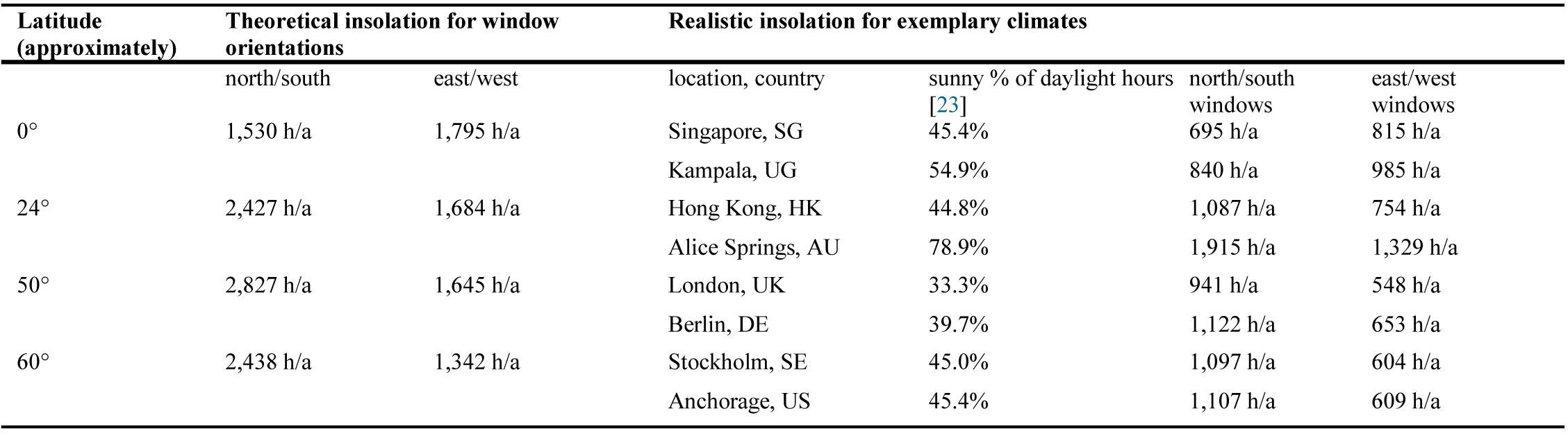
Table 1. Theoretical and realistic hours of sunlight redirection for latitudes, orientations, and exemplary locations.
2.3. Illuminance and energy saving in sunlit rooms
The illumination of rooms by redirected sunlight can be calculated for defined solar positions at a specific time of the year and day [20]. Simulation tools like DIALux or RELUX use bi-directionally measured data [18] of sunlight redirecting systems.
The development of advanced light directing structures in the TaLED project made it necessary to test the viability of all simulation results by measurements [12]. The following steps of validation have been carried out:
- Geometry and roughness of the microstructure samples, manufactured in hot and UV-embossing technology according to the design, were measured microscopically and rebuilt digitally.
- Light transmittance distribution was simulated for the realistically rebuilt samples and compared with the original design results. If necessary, proposals for optimization were given to the manufacturers (Fig. 8).
- Measurement of main luminous parameters for optimized samples: light transmittance (integrating sphere) and bidirectional transmittance distribution function (goniophotometer). BTDF data is transferred to LDT format.
- LDT data is imported to simulation programme DIALux. Room illumination by sunlight redirecting system for different geographic locations, window orientations, and points in time: Luminance and illuminance on room surfaces (Fig. 9) are modeled. In addition, the annual daylight autonomy or relative exposure to light can be modelled by using the software tool “CFS Express”.
- Luminous parameters in test rooms under natural daylight conditions are measured (comparison of room with sunlighting system and reference room with conventional window (Fig. 10)).
Figure 8
![(a) Measured micro-structure and simulated light transmission distribution. (b) and (c) Example for UV-embossing technology [12].](figures/6-52-8.jpg)
Fig. 8. (a) Measured micro-structure and simulated light transmission distribution. (b) and (c) Example for UV-embossing technology [12].
Figure 9
![Illustrating simulated illuminance distribution in office room with south-facing windows for different vertical and horizontal angles of sunlight incidence. Latitude and day of the year are (a-c) 0° Dec. 21st (d-f) 20° N Sept. 21st, and (g-i) 51° N Sept. 21st. Daytime and angles of sunlight incident (verticle and horizontal) on south facing window are (a) Vert. 28°, Horiz. 17° at 8:00, (b) Vert. 67°, Horiz. 0° at 12:00, (c) Vert. 28°, Horiz. -63° at 16:00, (d) Vert. 26°, Horiz. 80° at 8:00, (e) Vert. 71°, Horiz. 0° at 12:00, (f) Vert. 28°, Horiz. -80° at 16:00, (g) Vert. 16°, Horiz. 66° at 8:00, (h) Vert. 40°, Horiz. 0° at 12:00, and (i) Vert. 19°, Horiz. -66° at 16:00.
Room dimensions are l×w×h = 5 m×4.8 m×3 m and window height is 0.5 m. [12].](figures/6-52-9.jpg)
Fig. 9. Illustrating simulated illuminance distribution in office room with south-facing windows for different vertical and horizontal angles of sunlight incidence. Latitude and day of the year are (a-c) 0° Dec. 21st (d-f) 20° N Sept. 21st, and (g-i) 51° N Sept. 21st. Daytime and angles of sunlight incident (verticle and horizontal) on south facing window are (a) Vert. 28°, Horiz. 17° at 8:00, (b) Vert. 67°, Horiz. 0° at 12:00, (c) Vert. 28°, Horiz. -63° at 16:00, (d) Vert. 26°, Horiz. 80° at 8:00, (e) Vert. 71°, Horiz. 0° at 12:00, (f) Vert. 28°, Horiz. -80° at 16:00, (g) Vert. 16°, Horiz. 66° at 8:00, (h) Vert. 40°, Horiz. 0° at 12:00, and (i) Vert. 19°, Horiz. -66° at 16:00. Room dimensions are l×w×h = 5 m×4.8 m×3 m and window height is 0.5 m. [12].
Figure 10
![Comparison of measurements of daylight autonomy (relative exposure to light, EN 17037) in test rooms (window with sunlight redirecting system vs. conventional window) [12].](figures/6-52-10.jpg)
Fig. 10. Comparison of measurements of daylight autonomy (relative exposure to light, EN 17037) in test rooms (window with sunlight redirecting system vs. conventional window) [12].
The validation of performance by tests and detailed simulations included studies for different architectural applications. They have shown that sunlighting systems can illuminate classrooms, shopping centers, and workshops up to a depth of 10 m from the windows, depending on the height of room and windows. Other architectural applications are high and narrow rooms like atria sunlit by skylights [24]. The examples demonstrate that the illuminance by sunlighting is sufficient in nearly all situations with insolation on the windows, i.e. latitudes from 0° to 51°, seasons from winter to summer and daytimes from morning to afternoon. The mean horizontal illuminance mostly is higher than recommended by international standards: 300 lx to 500 lx for indoor workplaces according to EN 12464-1 [23]. This means that the artificial lighting system is switched off by the automatic control, and electricity is saved. In addition, the visual performance and the quality of lighting are improved.
Based on the detailed simulations by DiaLux, a tool that can be applied in the later design stages, a simple tool for the early design stages was developed to estimate the annual hours of sufficient sunlighting. The methodology uses insolation hours of window orientations from sunpath diagrams and statistical cloudiness of climate zones.
The energy savings for lighting can be derived from the sunlighting hours, assuming that conventional windows with activated solar control systems make artificial lighting necessary. Depending on the wattage of the lighting system, e.g. 10 W/m² for LED lighting, the energy savings can be calculated according to Table 2. The energy savings for lighting are economical (2 years return of investment is assumed realistic) and the improved lighting quality will increase work efficiency of occupants.
Table 2
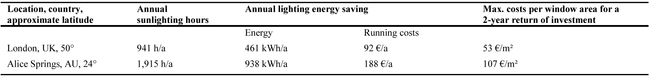
Table 2. Examples of energy savings and investments for sunlighting systems for office- or class-room, 7 m×7 m, 3 m high, south-facing, redirecting window area 3.5 m². Artificial lighting of 10W/m² was installed. Energy price of 0.20 €/kWh is estimated.
3. Conclusions
Micro-optical structures for sunlight redirection can be applied in a wide range of latitudes from the equator (0°) up to 60° N and S. Sun-path diagrams are a simple tool to estimate the annual time of utilization, especially in combination with cloudiness of climatic regions and resulting sunny percentage of daylight hours. Significant energy savings for artificial lighting can be achieved. The quality of room illumination is increased by the daylight spectrum and high illuminances well beyond standard minimum performance. The current research project [12] will provide optimized micro-structures to be manufactured in hot- or UV-embossing technology. Large-scale production and wide range of geographic applicability will reduce the unit costs and increase the economy of energy saving. Work efficiency of occupants is increased additionally by better lighting.
Acknowledgements
The joint research project TaLED, running 2016 to 2019, is funded by the German Federal Ministry for Economic Affairs and Energy and the partners.
References
- N. Ruck, Ø. Aschehoug, S. Aydinli, J. Christoffersen, G. Courret, I. Edmonds, R. Jakobiak, M. Kischkoweit-Lopin, M. Klinger, E. Lee, L. Michel, J.-L. Scartezzini, and S. Selkowitz, Daylight in Buildings, International Energy Agency, Washington, DC, USA, 2000.
- S. Klammt, H.F.O. Müller, A. Neyer, Microoptics for Efficient Redirection of Sunlight, Applied Optics 51 (2012) 2051-2056. https://doi.org/10.1364/ao.51.002051
- S. Klammt, A. Neyer, and H. F. O. Müller, Redirection of Sunlight by Microstructured Components - Simulation, Fabrication and Experimental Results, in: CISBAT 14-16 Sept. 2011, EPFL Lausanne, CH. https://doi.org/10.1016/j.solener.2012.02.034
- A. Thanachareonkit, E. S. Lee, and A. McNeil, “Empirical Assessment of a Prismatic Daylight-Redirecting Window Film in a Full-Scale Office Testbed, LEUKOS 10 (2013) 19–45. https://doi.org/10.1080/15502724.2014.837345
- R. Padiyath, Daylight Redirecting Window Films, 3M Company, pp. 217, 2013.
- T.Y. Huang, H. Hocheng, T.H. Chou, W.H. Yang, C.J. Ting, K.Y. Cheng, C.W. Hsieh, Design and fabrication of sunlight-redirecting and infrared-insulating microstructure, Energy and Buildings Vol. 90 (2015) 114-126. https://doi.org/10.1016/j.enbuild.2014.12.051
- H. Hocheng, T.Y. Huang, T.H. Chou, W.H. Yang, Microstructural Fabrication and Design of Sunlight Guide Panels of Inorganic-Organic Hybrid Material, Energy and Buildings, Vol. 43 (2011) 1011-1019. https://doi.org/10.1016/j.enbuild.2010.12.027
- T.H. Chou, W.H. Yang, T.Y. Huang, H. Hocheng, Roll-to-Roll Embossing of Sunlight Guide Film with Wide Outgoing Angle, International Journal of Automation Technology Vol. 5(2) (2011) 212-217. https://doi.org/10.20965/ijat.2011.p0212
- R. Padiyath, EW-201014, Daylight Redirecting Window Films, 3M Company, available: https://www.serdp-estcp.org/Program-Areas/Installation-Energy-and-Water/Energy/Conservation-and-Efficiency/EW-201014.
- J. Wienold, Dynamic Daylight Glare Evaluation, in: 11th International IBPSA Conference, 2009, pp. 944-951, Glasgow, Scotland.
- J. Wienold, Dynamic simulation of blind control strategies for visual comfort and energy balance analysis, in: Building Simulation, 2007, Beijing, China.
- Research Reports of Project TaLED (Energy- and cost efficient, façade integrated Day- and LED lighting based on mico-optical components), 2016–2019. Partners: RIF e.V., Karl Jungbecker GmbH, Temicon GmbH, Durlum GmbH, Saint-Gobain Securit GmbH, Green Building R&D GmbH, ai3, SSP AG. Funding: German Federal Ministry for Economic Affairs and Energy. Co-ordination: Fraunhofer Institute Building Physics, Stuttgart, Germany.
- M. Jakubowsky, A. Neyer, H. Müller, Microstructured Façade Elements for Energy Efficient Office Room Illumination by Sunlight combined with LED Light, in: South African Solar Energy Conference (SASEC2018), 2018, Durban, South Africa.
- Energy Performance in Buildings Directive, EPBD, EU 2018/844, available: https://eur-lex.europa.eu/eli/dir/2018/844/oj.
- CEN European Daylight Standard, EN 17037, Daylight of Buildings, 2018.
- P. R. Tregenza, I. M. Waters, (1983). Daylight coefficients, Lighting Research & Technology, 15(1983), 65–71. https://doi.org/10.1177%2F096032718301500201
- P.J. Littlefair, Daylight coefficients for practical computation of internal illuminance, Lighting Research and Technology 24 (1992) 127-135. https://doi.org/10.1177/096032719202400302
- M. Andersen, J.-L. Scartezzini, l. Michel, C. Roecker, H.P. Baumann, R. Brunkhorst, H. Coldewey, Bi-directional photogoniometer for the assessment of the luminous properties of fenestration systems, CTI Project Scientific Report, LESO-PB, EPFL, Lausanne, 2000.
- B. Bueno, E. Guidolin, J. Wienold, T. E. Kuhn, A Radiance-based building energy model to evaluate the performance of complex fenestration systems, in: ASHRAE/IBPSA-USA Building Simulation Conference, 2014, Atlanta, Georgia.
- C. Basurto, J. H. Kämpf, and J.-L. Scartezzini, Annual Performance Assessment of Complex Fenestration Systems in Sunny Climates Using Advanced Computer Simulations, Journal of Daylighting 2 (2015) 32-43. http://dx.doi.org/10.15627/jd.2015.6
- H.F.O. Mueller, Efficiency of Micro-Structured Sunlighting Systems in Different Climatic Zones, in: WREC XVIII, 2018, Kingston University, London, UK.
- A.J. Marsh, Sun-Path Diagrams, 2014. Available: http://andrewmarsh.com/apps/releases/sunpath2d.html.
- Current Results, weather and science facts, available: https://www.currentresults.com/Weather/Singapore/weather-averages.php#su.
- H.F.O. Mueller, Micro-optical Structures for Daylighting and LED Systems, Renewable Energy and Environmental Sustainability, 2 (2017) 29. https://doi.org/10.1051/rees/2017044
Copyright © 2019 The Author(s). Published by solarlits.com.

1821
Total views
Citations
SHARE ON


