Volume 7 Issue 1 > pp. 73-83 • doi: 10.15627/jd.2020.6
Power Factor Correction of Compact Fluorescent and Tubular LED Lamps by Boost Converter with Hysteretic Control
Javier Revelo-Fuelagán,a John E. Candelo-Becerra,b Fredy E. Hoyos*,c
Author affiliations
a Faculty of Engineering, Department of Electronics, Universidad de Nariño, Pasto, Colombia
b Faculty of Mines, Department of Electrical Energy and Automation, Universidad Nacional de Colombia, Sede Medellín, Carrera 80 No. 65-223, Robledo, Medellín 050041, Colombia
c Faculty of Science, School of Physics, Universidad Nacional de Colombia, Sede Medellín, Carrera 65 No. 59A, 110, Medellín 050034, Colombia
* Corresponding author.
javierrevelof@udenar.edu.co (J. Revelo-Fuelagán)
jecandelob@unal.edu.co (J. E. Candelo-Becerra)
fehoyosve@unal.edu.co (F. E. Hoyos)
History: Received 8 February 2020 | Revised 7 March 2020 | Accepted 24 March 2020 | Published online 2 April 2020
Copyright: © 2020 The Author(s). Published by solarlits.com. This is an open access article under the CC BY license (http://creativecommons.org/licenses/by/4.0/).
Citation: Javier Revelo-Fuelagán, John E. Candelo-Becerra, Fredy E. Hoyos, Power Factor Correction of Compact Fluorescent and Tubular LED Lamps by Boost Converter with Hysteretic Control, Journal of Daylighting 7 (2020) 73-83. http://dx.doi.org/10.15627/jd.2020.6
Figures and tables
Abstract
Compact Fluorescent Lamps (CFLs) and Light-emitting Diode (LED) lamps have received wide acceptance in lighting applications during the last few years. However, without a power factor correction (PFC), the lamps reach a lagging power factor below 0.64 while the total harmonic distortion (THD) in the input current can be over 136%. Therefore, this paper presents an efficient, small size, low cost, and analog technology based on PFC for CFLs and tubular LED lamps. The topology to couple the line with the ballast of the lamp consists of a boost electronic converter under a hysteretic controller that is designed based on hysteretic current mode control. Besides, an experimental prototype is implemented with the PFC applied to a 15 W CFL and 12 W tubular LED lamp. The results show that the prototype corrects the lagging power factor to a value close to 0.98 and that harmonic levels are obtained below the limits set by the IEC 61000-3-2 Class C standard. Furthermore, the test showed that lamps with the PFC can be switched on and off more times than lamps without the PFC due to the low THD produced in the CFL, thus avoiding abrupt changes in the line current. These results are promising, as the controller does not require a compensation ramp as in other PWM control strategies, and it can be adapted to any type of lamp that draws a pulsating input current. In addition, the proposed controller could be applied to correct the power factor or regulate voltage for other applications, as it is an autonomous control technique with compact implementation.
Keywords
Harmonics, Boost converter, Compact fluorescent lamp, LED lamp
1. Introduction
Nowadays, lighting systems are very important for humans because they can improve the quality of life, productivity, and development of a country [1]. In 2015, the largest final energy consumption in Europe was by the transport sector, which consumed 33.1% of the total amount of final energy, followed by the residential sector with 25.4% and the industry sector with 25.4% [2]. When the residential sector is considered, lighting consumption is one of the basic end uses in all households and it may come to represent 15–20% of the total electricity bill [3].
Compact Fluorescent Lamps (CFLs) and Light-emitting Diode (LED) lamps are gradually replacing conventional incandescent lamps due to their low energy cost and have received wide acceptance in household, commercial, and industrial lighting applications [4]. Particularly, the CFL includes a high-frequency electronic ballast that is placed at its base, which allows its small size, high lighting efficiency, and long lifetime [5,6]. On the other hand, LED lamps have some advantages such as color control, hue light control, high luminous efficiency [7], long life cycle, lower energy consumption, and resistance to shocks, and are environmentally friendly [3,8]. However, as the high-frequency electronic ballast of CFLs is connected to the AC voltage line, the rectifier circuit and the capacitor draw a pulsating input current that produces a low power factor and high harmonic distortions. Besides, LED lamps also have some drawbacks such as high cost, current distortion, and lower light efficiency compared with fluorescent bulbs.
Harmonic distortion introduced by CFLs has been studied in previous investigations as in [9], where the harmonic spectrum and total harmonic distortion (THD) are calculated with a Fourier analysis of the current waveform. The authors compared the harmonic spectrum and THD for Self-ballasted Fluorescent Lamps (SBLs) and CFLs, and discovered odd harmonics with higher amplitude for CFLs. They also found that the THD of CFLs is less than that of SBLs because the spectrum of SBLs includes more harmonics than that of CFLs, which introduces issues to the electrical grid (network); therefore, new techniques are necessary to improve the power factor.
Some authors have proposed two-stage power converter topologies for CFLs [10,11]. The first stage concerns the power factor circuit (PFC) circuit, which is a boost converter with its PFC controller. The second stage consists of a high-frequency resonant DC–AC inverter, which is used to turn ON the lamp and to provide the steady state current corresponding to nominal operation. In [12], the authors proposed electronic ballast for CFLs that has a PFC and half bridge converters integrated. Two independent converters were proposed such as the inverter and the PFC. This paper reports that the power factor obtained by simulation was 0.992 with a THD of 12.6% of the input current. Although the power factor is high, the THDs can be improved with better techniques. In [13], the authors proposed a novel single-stage single-switch resonant inverter with a high power factor for electronic ballast. The power factor correction circuit is at the input side and is designed to operate at discontinuous conduction mode. The lamp power is controlled by adjusting the duty cycle of the active switch of the power factor correction circuit.
The use of single-stage topologies in CFLs has the advantage of small size and low cost [14–16]. For example, in [16], the authors presented a new single-stage high-power factor electronic ballast based on a flyback converter to supply a fluorescent lamp. The system allows a high-input power factor for the utility line. Besides, in [17], the authors presented a single-stage high-power factor high-efficiency electronic ballast for compact fluorescent lamps. The authors demonstrated that the proposed topology is simple, reaches a high power factor, achieves a low current crest factor, and is efficient. Furthermore, the authors of [14] presented a single-stage high-power factor electronic ballast obtained from the integration of a buck DC–DC converter and a half-bridge resonant inverter. They worked on improving reliability, cost, efficiency, and lamp life. Finally, the authors of [15] presented a single-stage dimmable electronic ballast with very high power factor and high efficiency by integrating a buck-boost power factor corrector with a current-fed resonant inverter. Nevertheless, the single-stage ballast designs are not used in commercial CFLs due to the complexity of the involved controllers.
In [18], the authors presented a simple single-switch electronic ballast with passive valley-fill power factor correction for CFL application. The proposed single-switch ballast circuit is able to achieve zero current switching to maximize the circuit efficiency. A simple feedback circuit with duty ratio control is also proposed to improve the high lamp current crest factor caused by the valley-fill circuit. However, they could only reduce the power factor to voltages close to 0.93 and the harmonic spectrum of this current is measured at THD = 23.6% in the current.
In this paper, a PFC controller based on a boost converter is added to the existing commercial ballast of the CFL and the circuit of the tubular LED lamp. The PFC works under a hysteretic controller implemented using analog technology. The topology to couple the line with the ballast of the lamp consists of a boost electronic converter under a hysteretic controller and designed based on hysteretic current mode control. The hysteretic variable frequency analog controller avoids the common drawbacks of fixed frequency digital and analog implementations stated in [19]. The developed system has several advantages with respect to those reported in the literature: a) the compact and small size design allows its placement at the base of the lamp, b) the quality of electric energy is improved as it provides a high power factor and low harmonic distortion, and c) the controller structure can be applied, generally, to lamps that draw pulsating current, for example, LEDs.
The remainder of this work is organized as follows. In Section 2, a description of CFL and tubular LED lamps, the driver designed with the PFC applied to tubular LED lamps, the hysteretic controller of the boost converter, and the experimental prototype with the proposed hysteretic controller are presented. Section 3 shows the results of the experimental test with the proposed hysteretic controller, numerical simulations, and experimental tests showing the functioning of the circuit for the CFL and tubular LED lamps. The last section summarizes with some concluding remarks.
2. Materials and methods
This section presents the mathematical model of the circuit, a description of the technique, the materials, and the methods used in the investigation. Therefore, the section is divided as follows: a description of the commercial CFL and tubular LED lamp, detailed explanation of the design of the PFC, and the model of the driver with PFC used for both lamps.
2.1. Description of compact fluorescent lamps
The schematic block diagram of the CFL connected to the line voltage is shown in Fig. 1. To conduct accurate current sensing, a circuit prototype was implemented in shunt configuration at the input of a commercial CFL. This circuit considers an AC power source in series with a resistor Rshunt=0.1 Ω to measure the current circulating through the system. The CFL has a nominal power of 15 W and it is connected to the circuit that feeds a voltage of 120 V AC and 60 Hz.
Figure 1
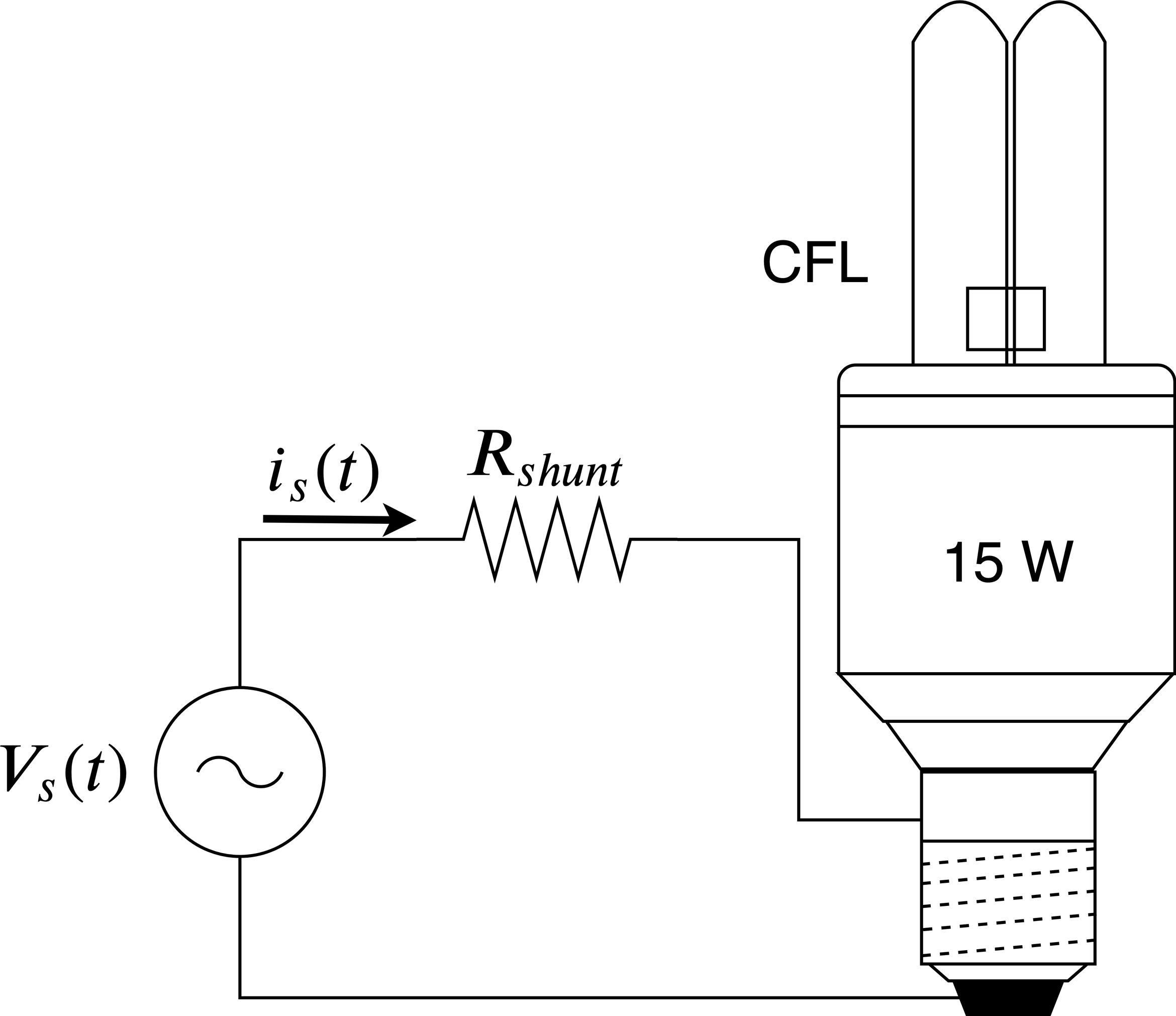
Fig. 1. Schematic block diagram of a CFL connected to the line voltage with a shunt resistor Rshunt for current measurement.
The characteristics of CFLs are defined in Table 1, where the reference of the lamp is Essential PLE15W127. The demanded RMS current of CFLs is lower than that of incandescent lamps, because the input current has a pulsating shape and it is null during the remaining time. Thus, this is the main cause of harmonic distortion that must be handled using a PFC controller.
Table 1
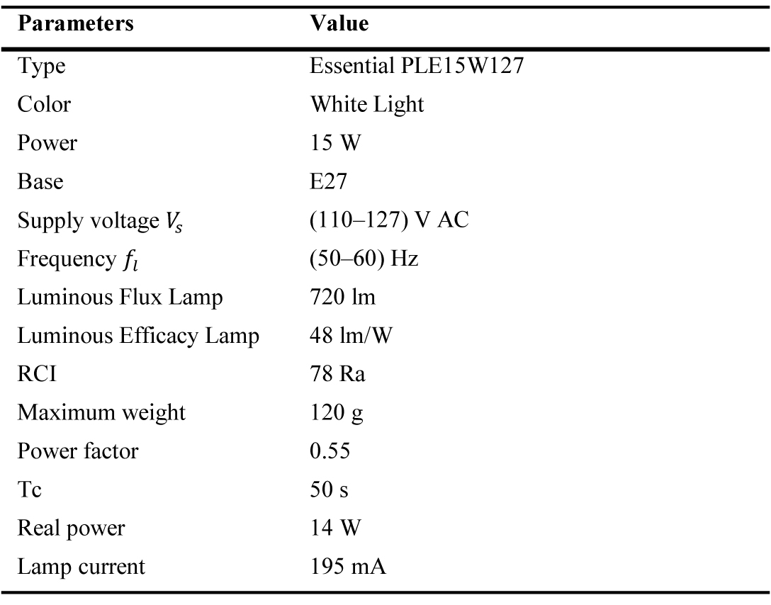
Table 1. Characteristics of the CFL.
Figure 2 shows the block diagram of a typical electronic ballast used in a commercial CFL. It consists of a full wave rectifier, following a DC link capacitor that carries out the AC to DC conversion and provides the energy needed to feed the resonant inverter [20]. Usually, the PFC controller is not incorporated in the ballast of commercial CFLs, resulting in a poor quality of current line, undesired harmonics, lagging power factors below 0.64, and THD of over 136%. With the use of CFLs, the consumption of electrical energy for the same luminosity is greatly reduced; however, as many CFLs are currently being connected, the large number of harmonics present in the electrical grid is becoming a problem [18,21].
Figure 2
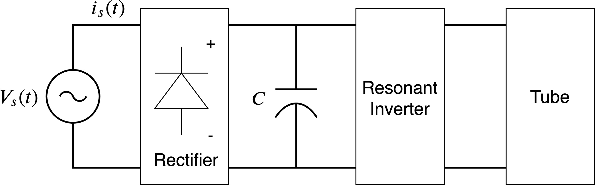
Fig. 2. Block diagram of electronic ballast in commercial CFLs.
2.2. Description of the commercial tubular LED lamp
The tubular LED lamp tubes are the equivalent option to traditional fluorescent tubes with the advantage of eliminating the electronic ballast and considering drivers that guarantee operation and energy savings. The main characteristics of the tubular LED lamp in front of the fluorescent tube are: energy savings (up to 60% compared with conventional fluorescent tubes); mercury- and polluting gas-free; longer duration; simple assembly to the electrical installation; no flickering or interference; instant start and shutdown; and others. The tubular LED lamp, used in this research, is the PlanetSaver R LED String reference shown in Fig. 3. The complete characteristic of the lamp can be found in Table 2.
Figure 3
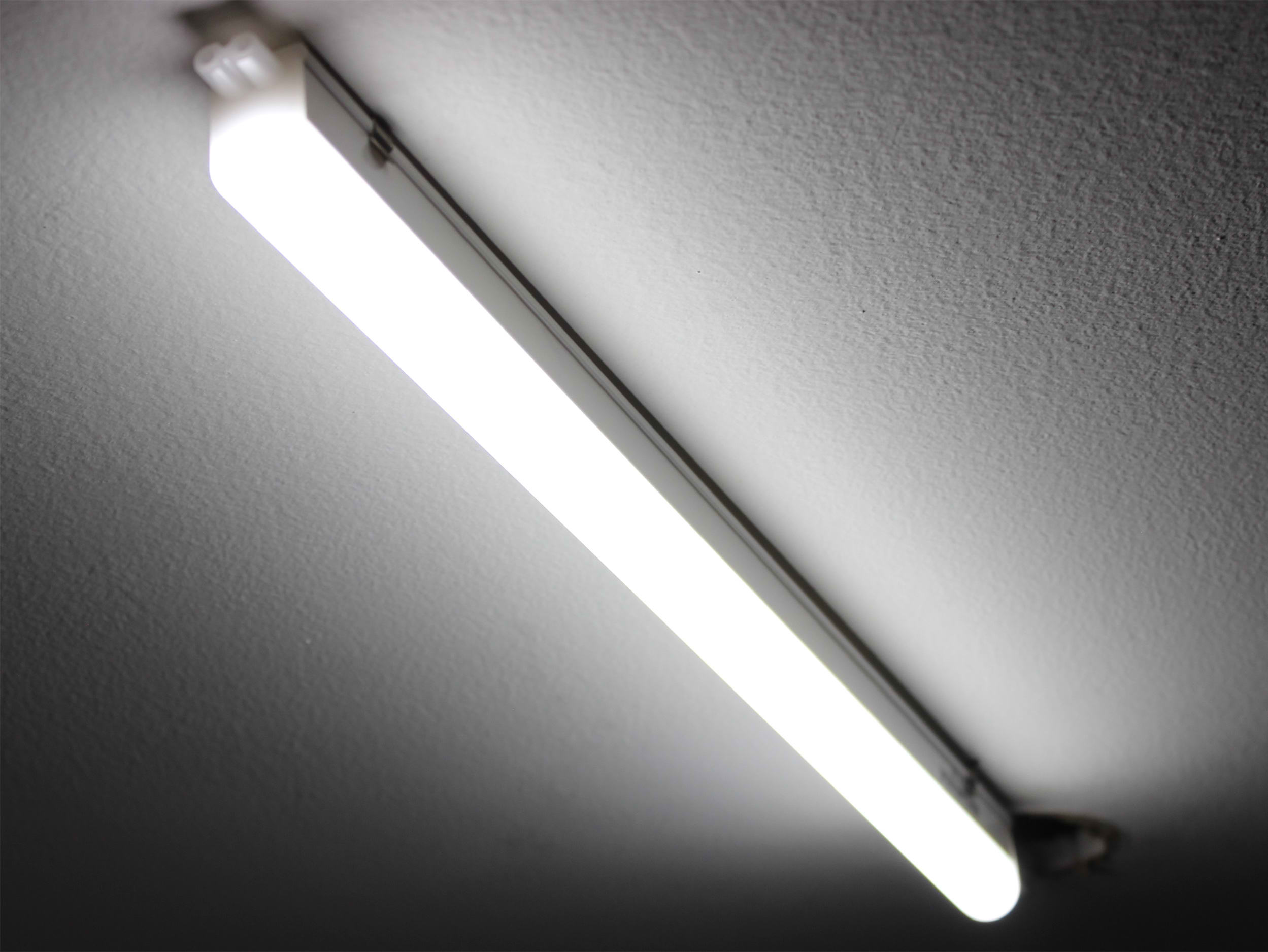
Fig. 3. Tubular LED lamp.
Table 2
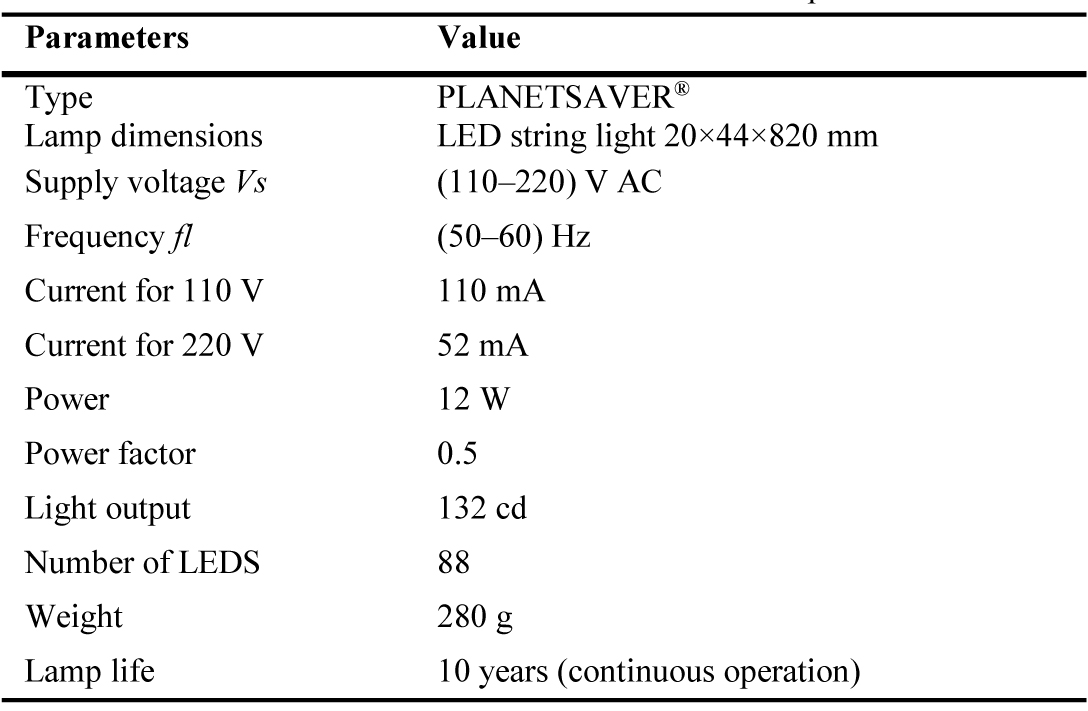
Table 2. Characteristics of the commercial tubular LED lamp.
Figure 4 shows the block diagram of a typical electronic ballast used in commercial tubular LED lamps. Internally, the lamp consists of 88 LEDs separated into two strings of 44 LEDs each with their own driver. Each driver consists of a diode rectifier, following a DC link capacitor that carries out the conversion from AC to DC and provides the energy needed to feed the resonant inverter [20]. Usually, the power factor circuit (PFC) controller is not incorporated and a large amount of undesired harmonics results in a low power factor that reaches values below 0.64, whereas the input current THD is over 100%. Therefore, the use of a PFC controller is mandatory.
Figure 4
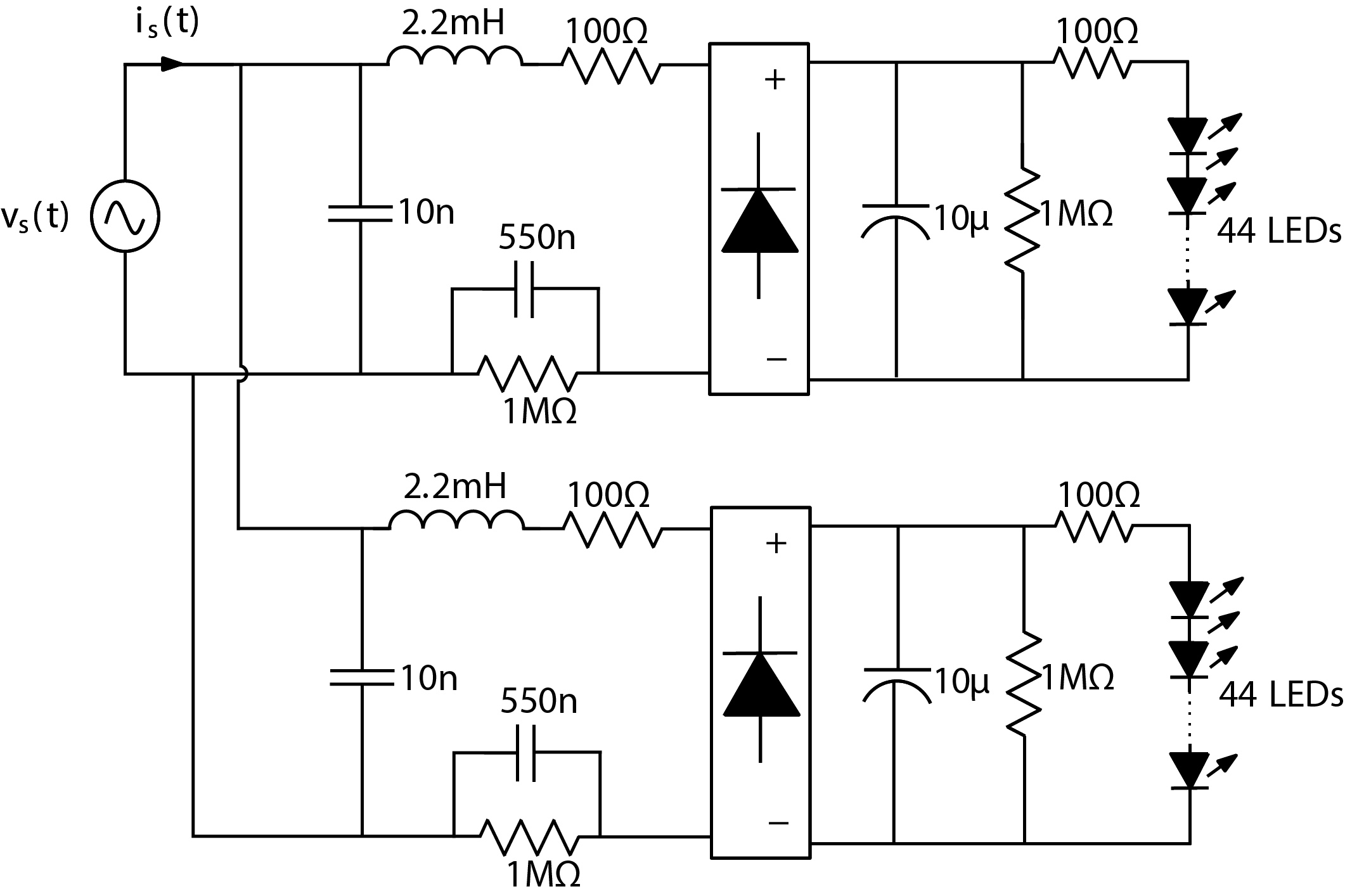
Fig. 4. Schematic block diagram of a commercial tubular LED lamp.
The demanded RMS current of LED lamps is lower than that of CFLs, because the input current has a pulsating shape and it is null during the remaining time. However, this is the main cause of harmonic distortion that must be handled using a PFC controller.
2.3. PFC control design
Various control methods and power electronics circuit topologies are used in PFC applications [17,19,22]; however, the continuous conduction mode (CCM) boost converter is commonly chosen. Therefore, the use of an inductor at the input of the boost converter brings advantages for the PFC, as it provides a continuous (non-pulsating) input current. Figure 5 shows the schematic diagram of a PFC boost converter working as a CFL driver. The boost converter is connected to the output of the full wave rectifier to deliver a DC voltage. The output of the boost converter is connected to the CFL electronic ballast and its input is connected to the AC line whose voltage is vs (t)=Vs sin(ωl t), where ωl=2πfl, fl is the line voltage frequency and Vs is its peak value. To achieve a high power factor, the current is(t) demanded by the load must track as well as possible the line voltage, i.e., is(t)=Issin(ωl t).
Figure 5
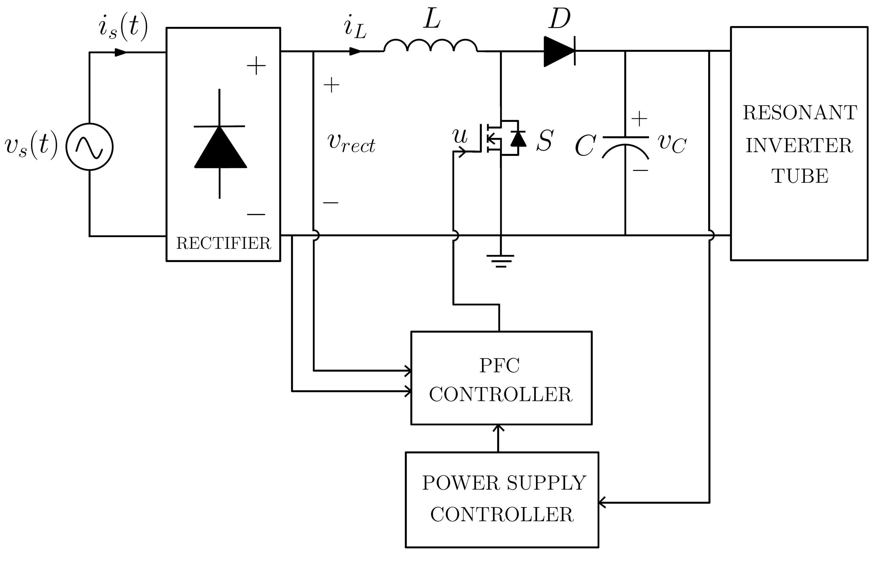
Fig. 5. Schematic diagram of a PFC boost converter working as a CFL driver.
Figure 6 shows the schematic diagram of a PFC boost converter working as an LED driver. The boost converter is connected to the output of the full wave rectifier to deliver a DC voltage. The output of the system (boost converter) is connected to the LED string.
Figure 6
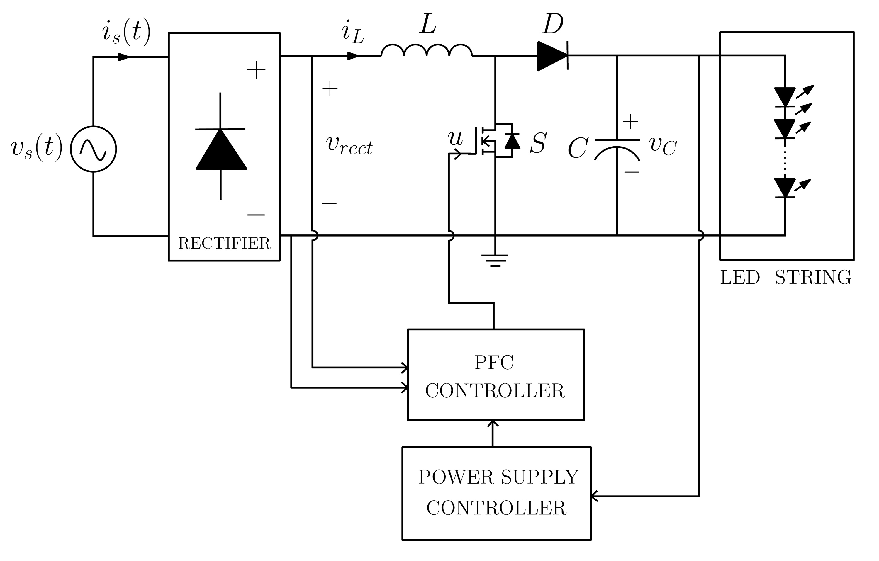
Fig. 6. Schematic diagram of a PFC boost converter working as a LED driver.
If the total power handled by the system is greater than 25 W, then the low-frequency harmonic content of the line current must comply with specific regulations [23]. Generally, for lighting equipment, the most widely used standard is IEC 61000-3-2 Class C [24]. However, in applications with power less than 25 W, which is the case of this work, IEC 61000-3-2 Class D must be fulfilled.
Because of the existence of a diode rectifier at the input of the boost converter, the resulting rectified input line voltage is given by Eq. (1):
The proposed control strategy for the current input loop is based on a hysteresis band with variable switching frequency [25,26]. A block diagram of the used control strategy that considers hysteretic control is shown in Fig. 7.
Figure 7
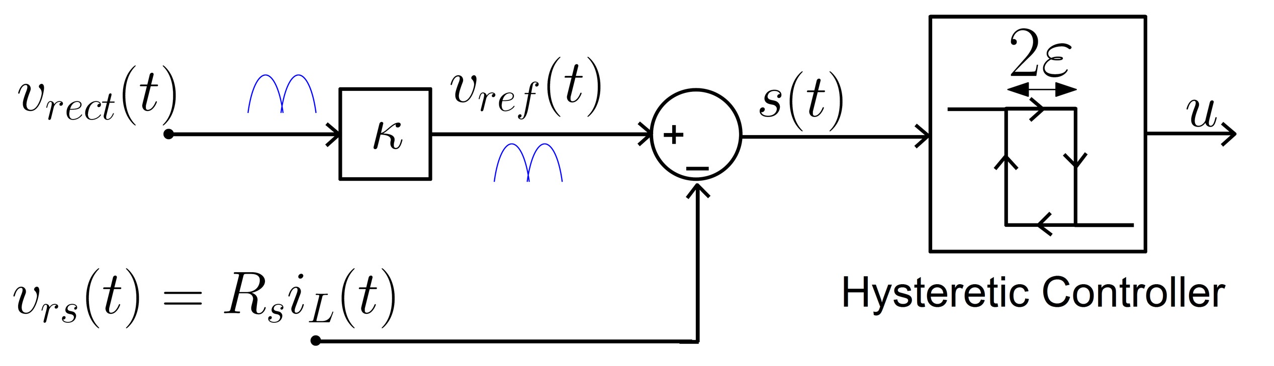
Fig. 7. Proposed controller for the PFC boost converter working as a CFL driver and as a LED driver.
A voltage vrs=RsiL and proportional to the boost inductor current iL is continuously compared with the reference voltage vref, obtained with κvrect(t) as expressed in Eq. (2), where κ is a fixed gain to amplify and obtain the reference voltage. Then, the error signal is introduced into a hysteresis comparator to obtain the control signal u. When the voltage vrs goes above the reference voltage vref, the driving signal u goes low, the switch turns OFF, and the current ramps down. When the voltage vrs goes below the reference voltage, the driving signal u goes high, the switch turns ON, and the inductor ramps up in such a way that it is always maintained within the hysteresis band. In the experimental circuit, the reference voltage vref (t) in the proposed controller is sensed at the output of the voltage divider:
The reference voltage vref (t)has a rectified sinusoidal waveform with a frequency twice the electrical grid frequency. The switching decision is, therefore, carried out and, consequently, the value of u is taken according to the following switching rule expressed in Eq. (3):
where s(t) is the error signal defined by s(t)=vref (t)-vrs(t) and ε stands for one-half of the hysteresis width. Under a tightly controlled current, the resulting rectified input line current is given by [25] as expressed in Eq. (4):
To determine the parameter, a power balance between the input and the output of the CFL is used, i.e., Pin=PLFC. Then, the average input power is defined by Eq. (5):
Herein, for one period, Tl=1/fl is the line voltage period. Therefore, using Is=κVs, the parameter κ is obtained as shown in Eq. (6):
The value of the parameter κ depends on the power consumed by the CFL or LED string and the resistor connected in series; therefore, if it is applied to a given lamp, then this parameter has a constant value.
For CFL, Pout is PLFC and for tubular LED Lamp, Pout is defined by Eq. (7):
The parameter ε of the proposed control strategy is selected in order to have an appropriate relative ripple amplitude ΔiL=100×2ε/is in the inductor current, which is varying from cycle to cycle. An acceptable range of this ripple is used from 10–30% [27]. Additionally, to select the value of ε, two aspects must be considered: first, a feasible switching frequency must be ensured for experimental implementation and, second, a low distortion in the input current.
2.4. Schematic circuit of the PFC of CFLs
Figure 8 shows the detailed circuit diagram of the studied system, which uses a control strategy with unipolar hysteresis band. The controller consists of an error generator and a unipolar hysteresis comparator. For this reason, an offset voltage Voffset is added to the control signal s(t). The power supply controller is formed by two amplifiers in Darlington configuration and regulated by a ZENER diode, providing a voltage of 10 V and a current of 10 mA. It is worth noting that the controller and its respective power supply consume a power P=3 W to supply the operational amplifiers (OAs) and for setting the value of Voffset. Note that the resonant inverter module and the power supply controller are supplied with the output voltage of the boost converter.
Figure 8
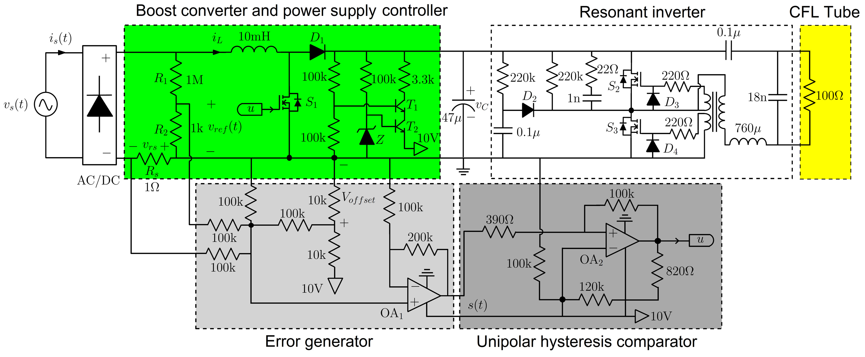
Fig. 8. Schematic circuit diagram of the implemented boost PFC converter for CFL.
Selection of the parameter κ is carried out by using a voltage divider with resistors R1 and R2 at the output of the rectifier bridge. The sum of the resistor values must fulfill the condition R1+R2>>rL+RON, where rL is the internal resistance of the inductor L and RON is the MOSFET resistance between its drain and its source in the conducting state. The demand for high values for R1 and R2 is to ensure that the current flowing through this branch is minimal compared with the current flowing through the inductor and the MOSFET. Table 3 summarizes the list of parameters and component values used in the design of the experimental circuit.
Table 3
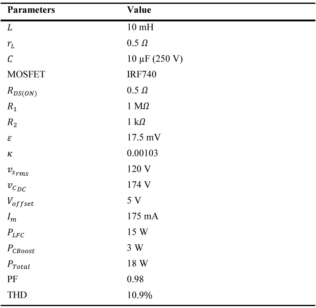
Table 3. Parameters of the circuit used for the CFL.
Finally, the circuit developed to perform the experimental test is presented in Fig. 9. This circuit has a full wave rectifier (AC/DC), boost converter, power supply controller, error generator, and unipolar hysteresis comparator. All these blocks were implemented to test the PFC for CFLs. It is important to note that the circuit developed in Fig. 9 fits exactly inside the CFLs.
Figure 9
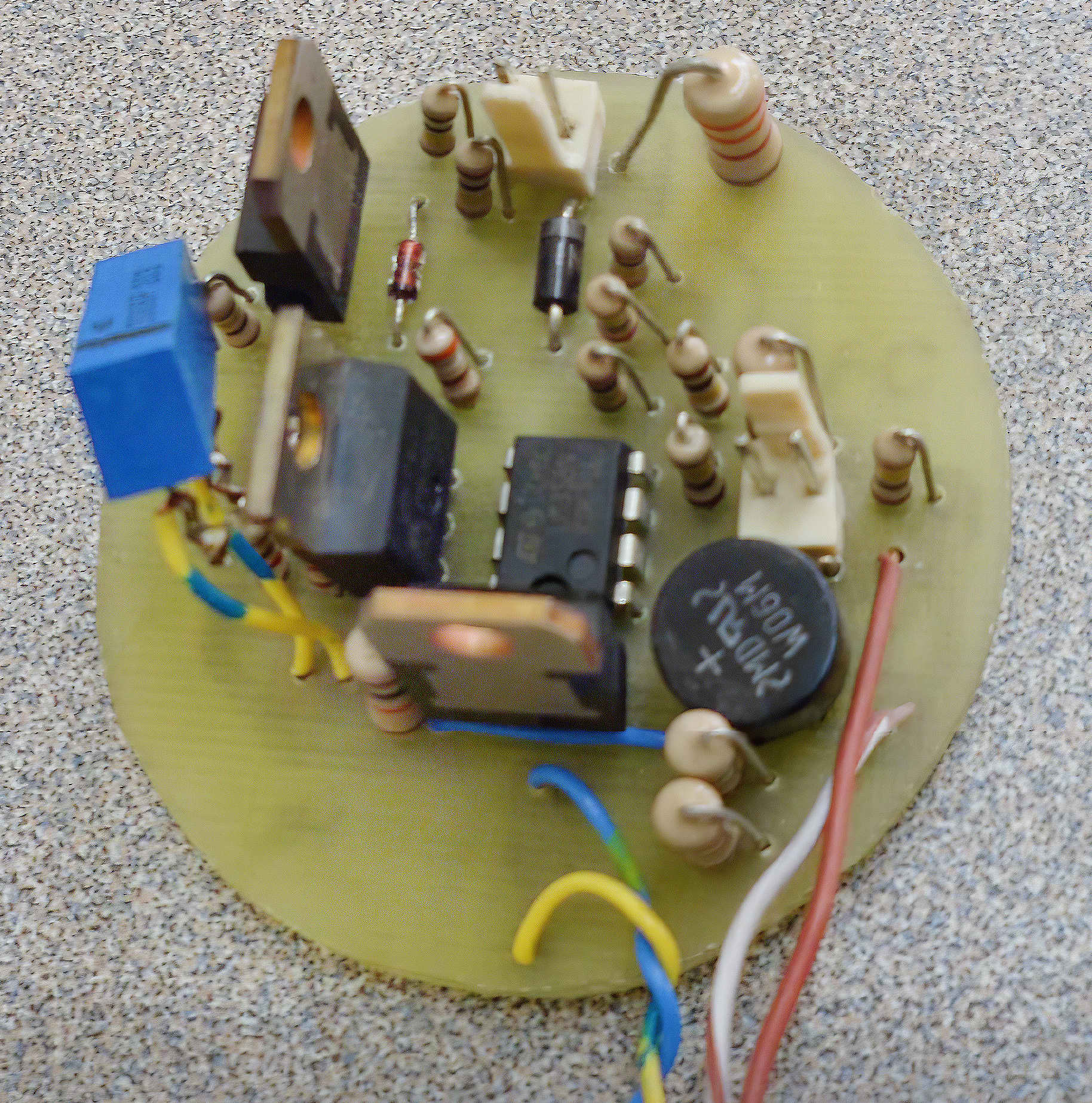
Fig. 9. Experimental development of the PFC for CFL.
2.5. Driver with PFC for tubular LED lamps
The design of an LED driver with PFC for a tubular lamp considers the same operating principle of the first design presented for the bulb-type LED lamp. The driver is mainly composed of the boost converter controlled with the hysteresis band-based technique. For correct operation of the LEDs string, it is necessary to supply a voltage and a current depending on the values established by the manufacturer, regardless of the power supply. However, as the new driver is designed for an input voltage of 220 VRMS, by changing certain parameters the input voltage can be adjusted to 110 VRMS. As the power consumption by the LED string is the same for different power supplies, when it is fed with a high voltage value, its current demand is minimal. Hence, it is amplified by a factor α all signals that enter the control and, thus, handle another comparison scale in the hysteresis band, thereby achieving greater precision and also differentiating the signals from the noise of the system. With the above, the control strategy diagram for the boost converter is shown in Fig. 10.
Figure 10
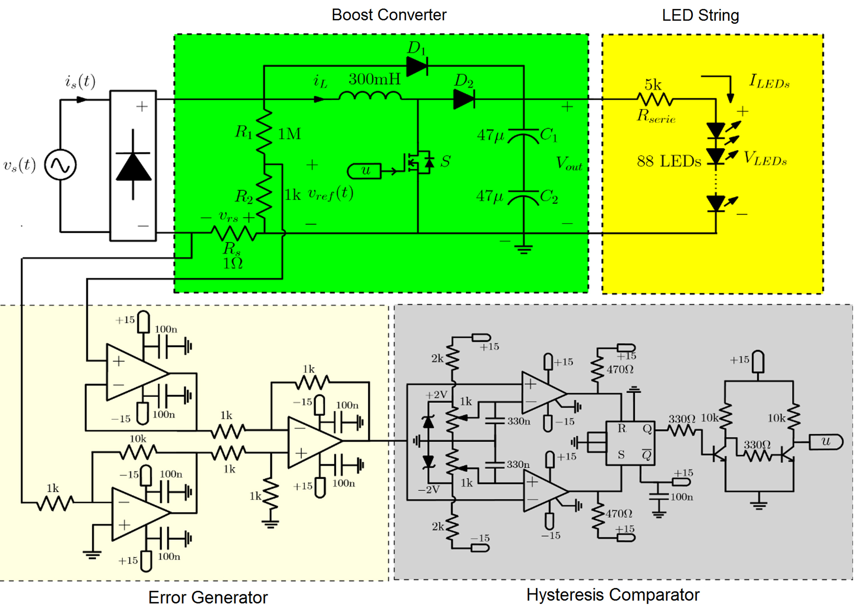
Fig. 10. Driver with power factor corrector (PFC) for the tubular LED lamp.
A diode is added between the input and output of the boost converter, which acts only in the transient state and has the function of directly charging the output capacitor at the instant of the lamp; reducing with this is the maximum value of the current during the transitory time. The last difference with respect to the first design of the driver has to do with the electronic circuit to configure the control with hysteresis band. For this opportunity, two comparison devices and a memory register are used to determine the control signal u with respect to the signal from the error generator. Table 4 summarizes the list of parameters and component values of the driver used for the tubular LED lamp.
Table 4
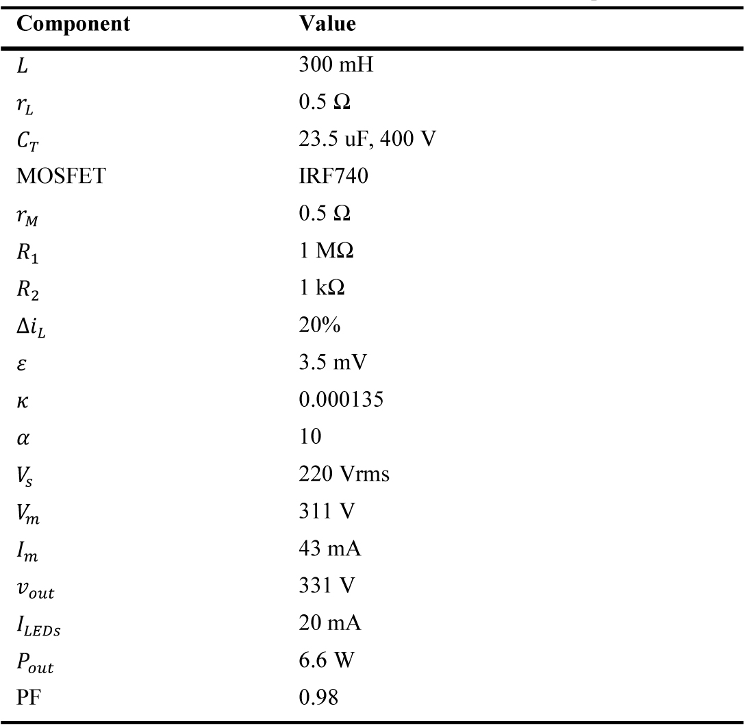
Table 4. Parameters of the Driver used for the tubular LED Lamp.
The circuit diagram is composed of four stages: the boost converter, the string of LEDs that is fed to the output of the converter, the error generator, and the hysteresis comparator; where the two last stages are used for the power factor correction.
The boost converter is fed from the output of the rectifier bridge and at the input of the converter is a voltage divider that represents the reference voltage vref to control the input current. At the output is a branch composed of two capacitors connected in series of 47 µV to 400 V each to ensure that the output voltage is distributed in an equal value in half in each capacitor. In addition, the link diode between the input and the output is added to the boost converter.
At the output of the converter, the string of 88 LEDs is coupled in series with the resistance that limits the current flowing through them. The configuration of LEDs is modified with respect to that established by the commercial lamp, in which two drivers are used to power 44 LEDs each. On the contrary, in the proposed design, the 88 LEDs are fed with only one driver as shown in Fig. 10. As a protection system, ZENER diodes are added to prevent the entire LED string from being disabled if any of them fail.
Finally, the controller is composed of two stages. The first one is the error generator that is designed based on low-speed operational amplifiers with the aim of filtering the high-frequency noise. The second one is the hysteresis comparator comprising two comparison devices and a memory register.
3. Results and analysis
3.1. Driver with PFC for compact fluorescent lamps
This subsection presents the results of the PFC tested for the CFL and is divided into numerical simulations, experimental results, and the harmonics evaluated for the circuit with and without the proposed solution.
3.1.1. Numerical simulations
Figure 11 shows the numerical simulations of the CFL with the PFC. The input line voltage is vs(t)=120√2sin(2π60t) as shown in the right Y axis of the figure. Besides, the current demanded by the CFL is shown in the left Y axis of the figure. Note that the input current is shaped according to the input voltage, which results in a high PF (0.99) and a low THD=10 %. This simulated result shows that the circuit allows correction of the power factor and obtains good performance.
Figure 11
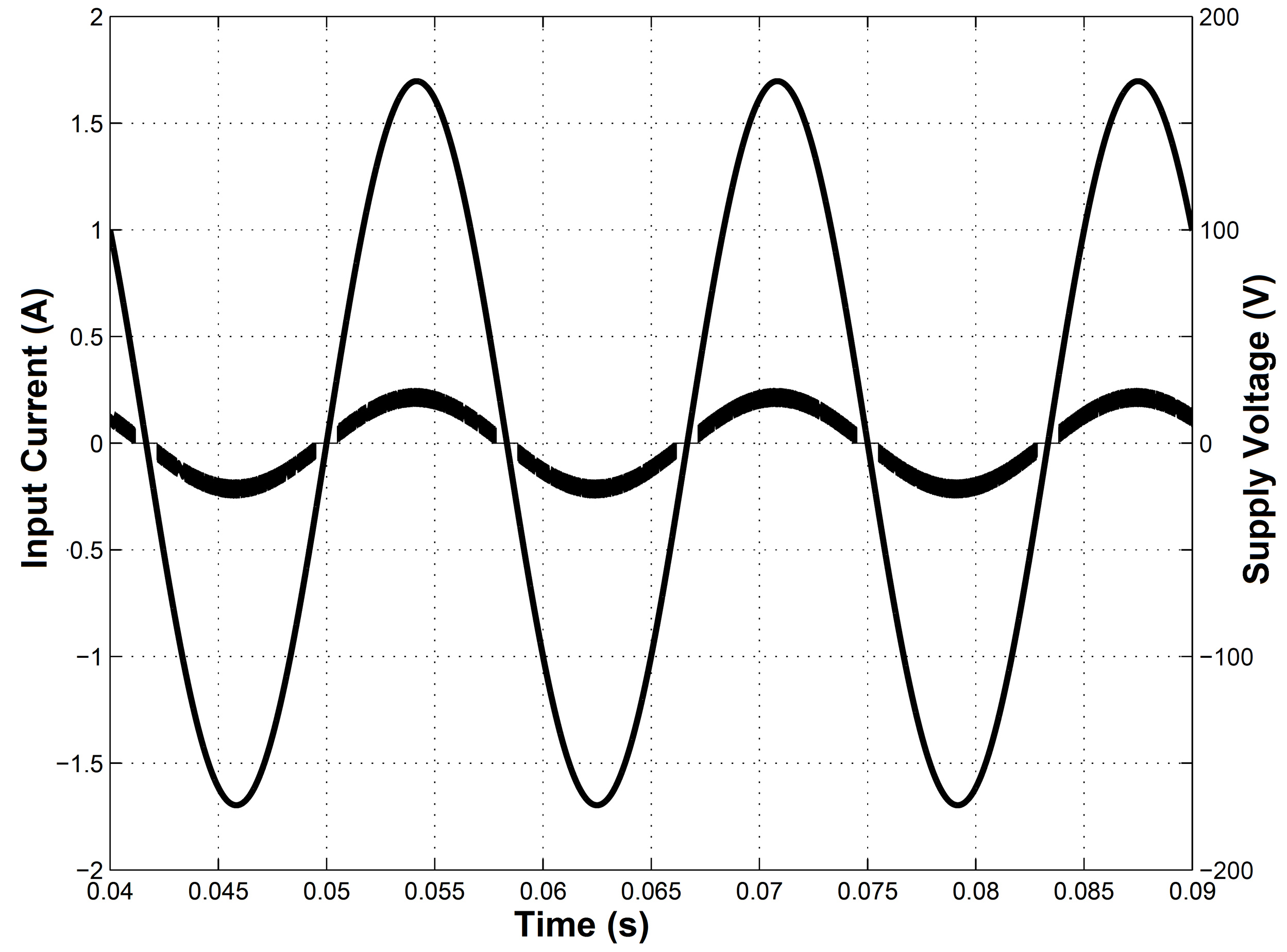
Fig. 11. Input line voltage and current obtained from numerical simulation using PSIM package with PF≈0.99 and THD≈10 %.
3.1.2. Experimental results
Several tests have been performed experimentally to analyze the effect of the control on the behavior and lifetime duration of the CFL. Each test has been performed with a pair of lamps: (i) a commercial lamp and (ii) another lamp of the same type with the proposed PFC control. Figure 12 shows the input voltage and input current demanded by the CFL and the values of power factor and the power consumed by the lamp as measured with a scopometer Fluke 192. In Fig. 12(a), the input current has a pulsating and distorted shape, generating a low power factor of 0.64 and a total power consumption of 15 W. Figure 12(b) shows that the controlled current in the CFL is in phase with and shaped according to the input voltage. The control allows a significant increase of the power factor to a value of 0.98 with a total power consumption of 18 W and it also reduces the harmonic distortion reflected in the low value of 10.9 %. The increase in power of 3 W is due to the consumption of the controller and its respective power supply.
Figure 12
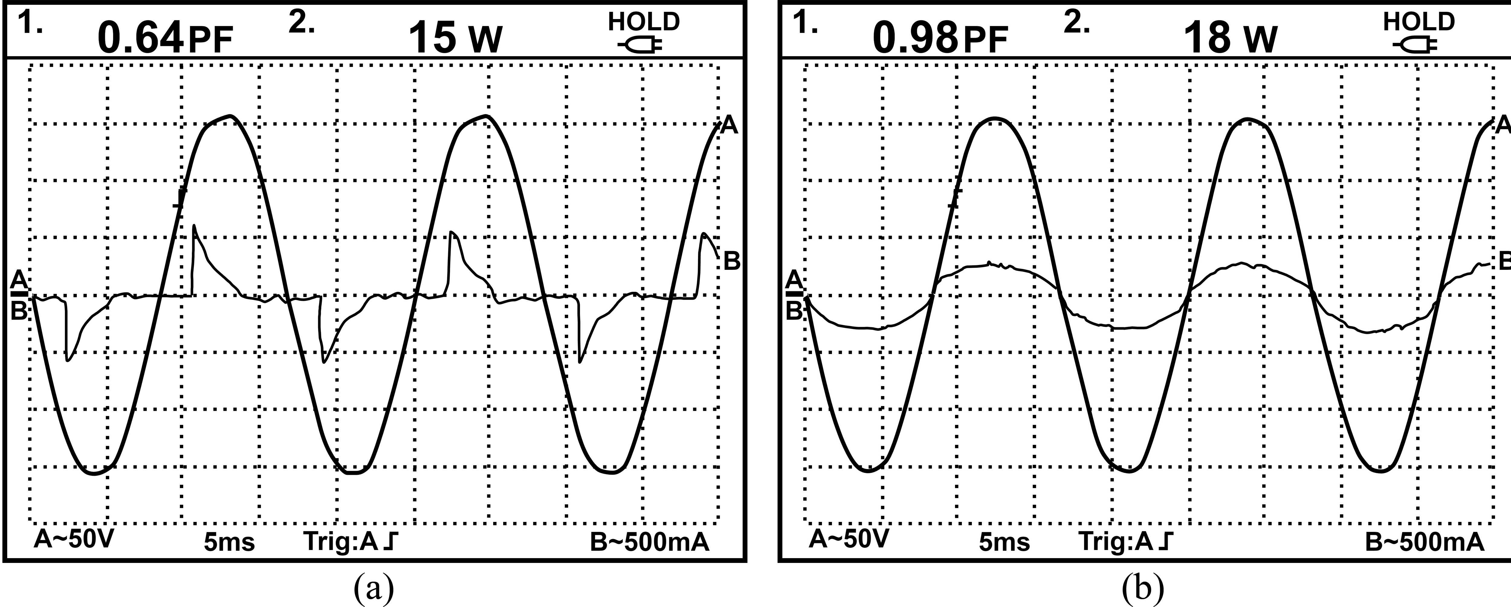
Fig. 12. CFL experimental waveforms, power, and power factor. Channel A: Input voltage; Channel B: Input current (a) CFL without designed controller (PF≈0.64, THD≈136 %) (b) CFL with designed controller (PF≈0.98, THD≈10.9 %).
In Fig. 12(a) and (b), the voltage has a gain is 50 V/div and, thus, the voltage signal has a peak value of 155 V. The current has a gain of 500 mA/div, whereas the current measured in Fig. 12(a) without the PFC has a value close to 600 mA and is pulsating. In Fig. 12(b), where the circuit includes the PFC, the current is sinusoidal and has a peak value of 250 mA, it can be seen that the two signals are sinusoidal and in phase.
Table 5 shows the results when the CFL with and without the PFC is switched on and off several times at 30 s intervals. This table shows the different times that each lamp supports the switching process and the average times of both lamps. The result shows that the lamps with the PFC last an average of 13,545 times, which is 79% more times than the lamps without the PFC (7,536.6 times). Therefore, the CFL that lasted more to the switching tests is the one that considered the designed PFC.
Table 5
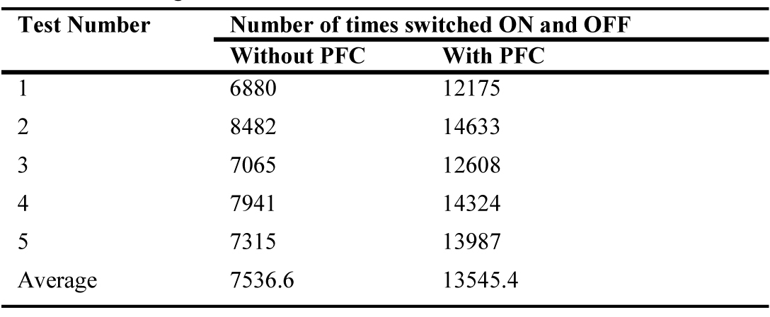
Table 5. Switching test for CFL with and without PFC.
3.1.3. Experimental results
Figure 13 shows the current harmonics of the CFL with and without the proposed PFC controller, in percent with respect to the fundamental one. From this figure, it can be observed that the commercial lamp without PFC controller has a high content of odd-order harmonics, which would deteriorate the line current when a set of lamps of this type is used. From the same figure, one can observe that the CFL with a PFC controller presents a significant reduction in the odd-order harmonics levels, thereby improving the quality of the electric power. It is observed that the fundamental harmonic remains the same for both cases, but other harmonics are significantly reduced such as the third (from 70% to 7% or 10 times), the fifth (from 38.5% to 3.8% or 10 times), the seventh (from 31% to 3% or 10.3 times), the ninth (from 28% to 2% or 14 times), the eleventh (from 17% to 1.7% or 10 times), and the rest of harmonics are smaller. The CFL without the PFC has high-order harmonics at near 5%, whereas the CFL with the PFC reduces high-order harmonics to close to 1%. Without the PFC the harmonics are greater than or equal to 10% up to the nineteenth harmonic, which is not appropriate for large numbers of lamps working in a power grid, whereas with the PFC, values are lower than 8% from the third harmonic.
Figure 13
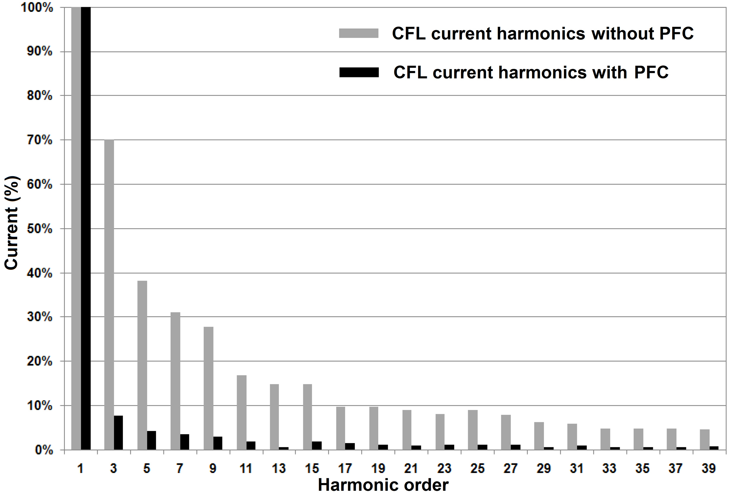
Fig. 13. Current harmonics of the CFL with and without the proposed PFC controller.
The IEC 61000-3-2 Class C standard for lighting loads with power below 25 W sets the levels of harmonics with respect to the power consumed by the CFL. Figure 14 shows that harmonics levels of the input current are below the limits set by this standard. This figure shows that the standard proposes larger values than those found in this research with the PFC; i.e., the third, fifth, and seventh harmonics proposed in the standard are much higher (by about three times) than those obtained with the PFC.
Figure 14
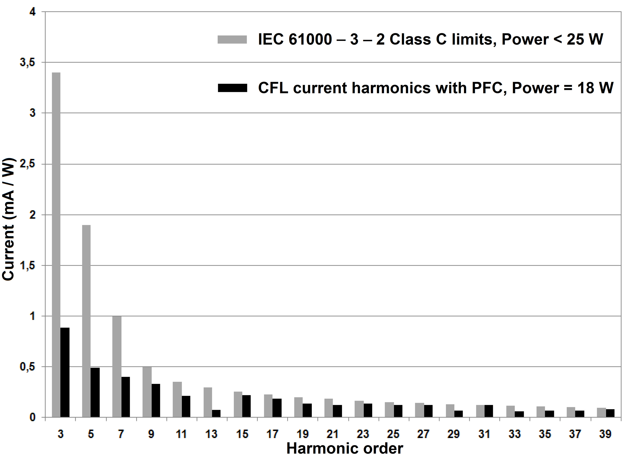
Fig. 14. Current harmonics of controlled CFL in comparison with the limits set by IEC 61000-3-2 Class C standard.
3.2. Driver with PFC for tubular LED lamps
This subsection presents the results of the new design of an LED driver with PFC for a tubular lamp. The driver is mainly composed of the boost converter controlled with the hysteresis band-based technique. The results consider the initial conditions for the lamp and the simulation and experimental tests with the power factor corrector. Furthermore, the experimental development for tubular LED lamp is presented in Fig. 15. Figure 15(a) shows the driver without PFC and Fig. 15(b) shows the driver with PFC. Finally, some conventional drivers that considers power factor correction can be found in commerce with a cost around US$ 9; however, in this paper a more efficient driver was designed with similar characteristics with a final cost around US$ 4.
Figure 15
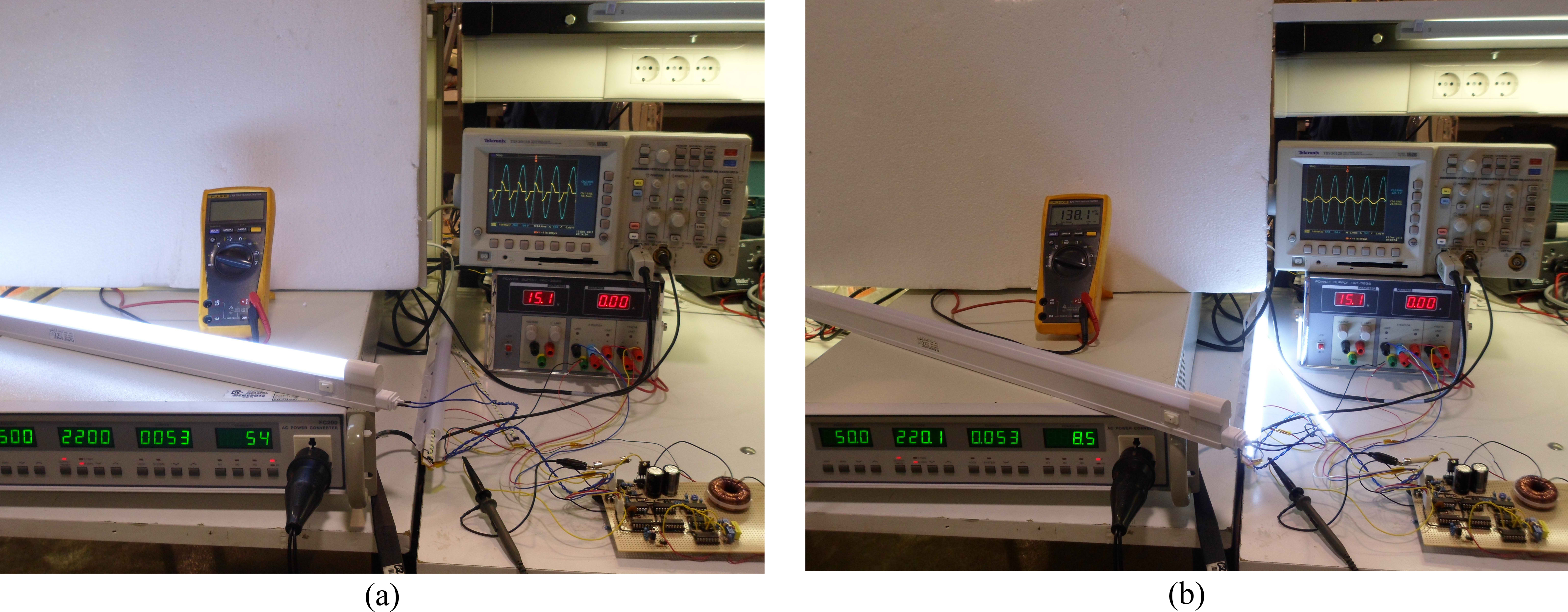
Fig. 15. Experimental development for tubular LED lamp (a) without PFC and (b) with PFC.
3.2.1. Initial conditions for the tubular LED lamp
For the entire lamp, the input power corresponds to the two drivers that allow operation of the LEDs. Figure 16(a) shows the voltage and current signals supplied by the power grid to energize the commercial lamp. These graphs were obtained by using the PSIM simulation package. Figure 16(b) shows the voltage and current signals of the commercial lamp registered in the power supply as obtained from the experimental setup. Note that the current presents changes in the form requiring a power factor correction. The power consumption of the tubular LED lamp is around 12 W as defined in Table 2.
Figure 16
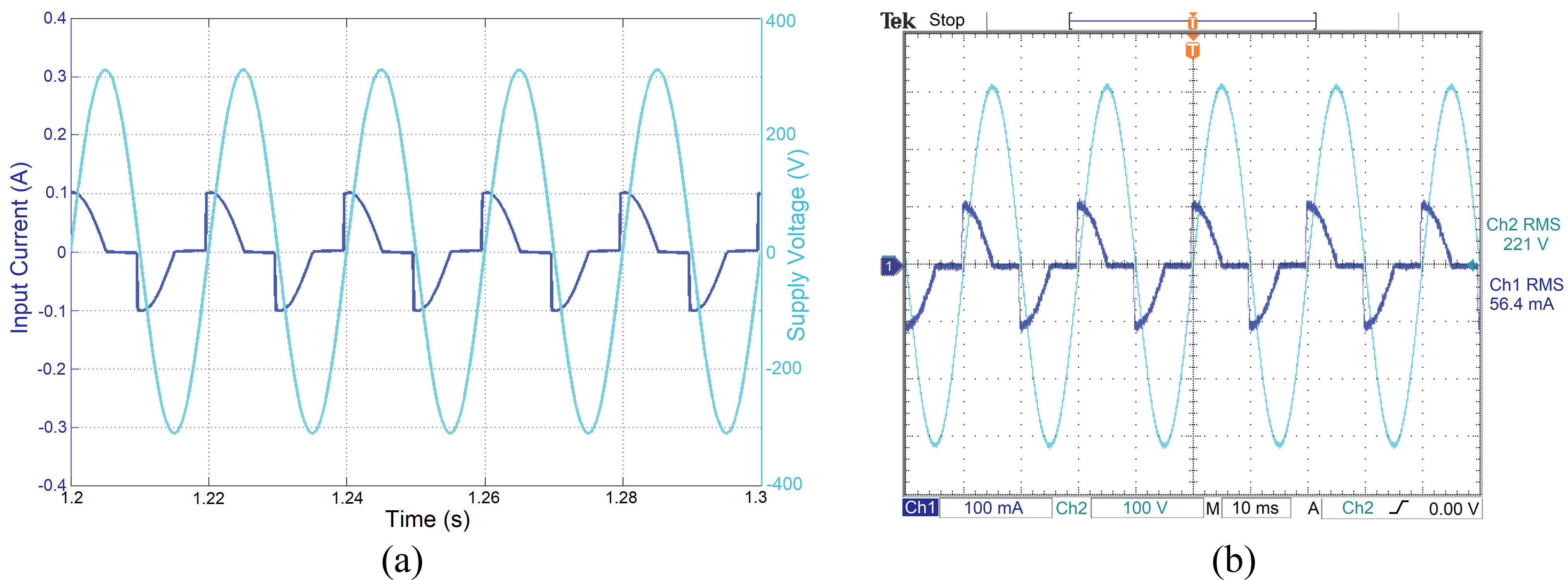
Fig. 16. Voltage and current (a) simulation test and (b) experimental test.
With the results obtained by the simulation and experiment tests, it was determined that the current commercial tubular LED lamps causes high distortions and affects the power quality in the network with a low power factor (0.64 lag). The drivers have passive filters at the input with the purpose of reducing the supply voltage, but with the disadvantage that they dissipate power in the form of heat and are also responsible for generating the gap between the voltage and input current. In Fig. 16(a), the input current has a pulsating and distorted shape, generating a low power factor of 0.64.
3.2.2. Power factor correction of tubular LED lamps
Figure 17(a) shows the voltage and input current signals obtained for the simulation test, and Fig. 17(b) shows the voltage and input current signals obtained for the experimental test when the power factor correction is used in the circuit.
Figure 17
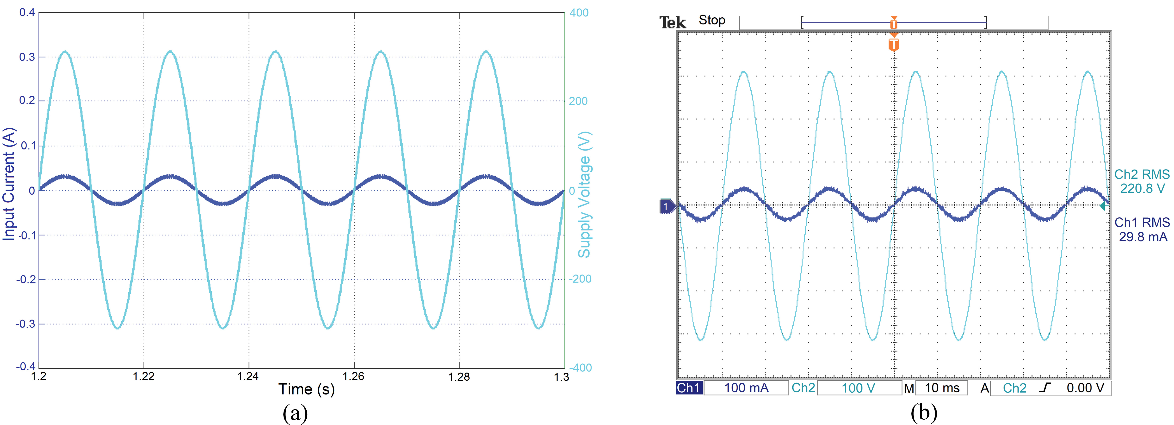
Fig. 17. Voltage and current (a) simulation test and (b) experimental test.
Both voltage and current signals are in phase and maintain the sinusoidal shape, reaching a power factor close to the unit. The simulation results were obtained with the PSIM software and the experimental results obtained from the implemented prototype were recorded using a 100 MHz TEKTRONIX TDS3012 oscilloscope. The result shows that the supply voltage and the current demanded measured in the experimental test are identical to those obtained in the simulation, fulfilling the power factor correction. The driver designed for the tubular LED lamp allows lower power consumption of around 6.6 W while the control allows a significant increase of the power factor value to 0.98.
4. Conclusions
In this paper, an analog controller has been proposed for PFC in CFLs and tubular LED lamps. The most important advantages of the controller are its low cost, small size, and low power consumption. Moreover, the controller does not require a compensation ramp as in the PWM control strategy. Additionally, it can be adapted to any type of lamp that draws a pulsating input current. The method considered a unipolar hysteretic controller supplied by a DC voltage taken from the own output of the system. Experimental results have been presented using 15 W CFL showing a power factor of 0.64 (THD=136.6%) without a PFC controller and power factor of 0.98 (THD=10.9%) with the proposed PFC controller. Furthermore, the implemented system allows a greater number of times that the CFL can be switched on and off (79% greater compared with the commercial lamps). This is due to the low THD in the CFL with the PFC controller, which avoids abrupt changes in the line current. Finally, the current harmonics are compared with the limits established by the IEC 61000-3-2 Class C standard for lighting loads under 25 W and all levels obtained were below the limits set by this standard.
Besides, the simulation and experimental results show the effectiveness of the entire controlled system, with a sinusoidal input current signal and for the output a constant current to power the LED string. The driver designed for the LED lamp reduced the power consumption from 12 W to 6.6 W. The commercial drivers have passive filters at the input with the purpose of reducing the supply voltage, but with the disadvantage that they dissipate power in the form of heat, and in addition, they are responsible for generating the gap between the voltage and the current input. The designed driver was basically made up of the electronic boost converter configured as PFC and controlled by hysteresis band; in addition, they are generalized for LED lamps of different presentation: bulb type and tubular. The implementation of the experimental prototype of the drivers is carried out with a technology analog to achieve a more accurate signal flow for the control and with a compact structure in order to incorporate it internally at the base of the lamp’s LEDs.
In future work, the implemented technique can be applied to correct the power factor or regulate voltage in other power converters as it showed to be an autonomous control technique with compact implementation. In addition, it is proposed to (a) generalize the control technique to other types of loads with the power factor correction function to improve the quality of electrical energy, (b) study different electromagnetic interference that the electronic converter can generate and alter the operation of other equipment, such as the vulnerability of being affected by external interference, and (c) design a power factor correction system and, at the same time, have the function of monitoring the quality measures of electrical energy by taking advantage of the benefits of digital technology.
Acknowledgment
This research received funding by the Universidad Nacional de Colombia, Sede Manizales and Sede Medellín under the projects HERMES-34671 and HERMES-36911. Also, authors acknowledge to the Research Group in Electrical and Electronic Engineering - GIIEE”, from Universidad de Nariño.
Contributions
The authors have contributed equally.
Declaration of competing interest
The authors declare that there is no conflict of interest.
References
- S. Bunjongjit, A. Ngaopitakkul, M. Leelajindakrairerk, Analysis of harmonics in indoor Lighting System with LED and fluorescent luminaire, in: 2017 IEEE 3rd Int. Futur. Energy Electron. Conf. ECCE Asia (IFEEC 2017 - ECCE Asia), IEEE, 2017, pp. 2129–2132. https://doi.org/10.1109/IFEEC.2017.7992380
- T. Serrenho, L. Castellazzi, N. Labanca, F. Diluiso, P. Bertoldi, Energy Consumption and Energy Efficiency Trends in the EU-28 2000-2015, Publications Office of the European Union, Luxembourg, 2018. https://doi.org/10.2760/6684
- E.J. Palacios-Garcia, A. Chen, I. Santiago, F.J. Bellido-Outeiriño, J.M. Flores-Arias, A. Moreno-Munoz, Stochastic model for lighting’s electricity consumption in the residential sector, Impact of energy saving actions, Energy Build. 89 (2015) 245–259. https://doi.org/10.1016/j.enbuild.2014.12.028
- R. Alammari, M.S. Islam, N.A. Chowdhury, A.K. Sakil, A. Iqbal, A. Khandakar, Impact on power quality due to large-scale adoption of compact fluorescent lamps – a review, Int. J. Ambient Energy. 38 (2017) 435–442. https://doi.org/10.1080/01430750.2015.1121921
- J.C.W. Lam, P.K. Jain, A High-Power-Factor Single-Stage Single-Switch Electronic Ballast for Compact Fluorescent Lamps, IEEE Trans. Power Electron. 25 (2010) 2045–2058. https://doi.org/10.1109/TPEL.2010.2046426
- S.M. Shyni, M.W. Abitha, C. Bhuvaneswari, Power factor improvement of compact fluorescent lightings with valley-fill circuit, in: 2017 Int. Conf. Comput. Power, Energy Inf. Commuincation, IEEE, 2017, pp. 622–626. https://doi.org/10.1109/ICCPEIC.2017.8290436
- C.L. and G.H. P. Wang, Y. Su, Improving Performance and Reducing Amount of Phosphor Required in Packaging of White LEDs With TiO2 -Doped Silicone, IEEE Electron Device Lett. 35 (2014) 657–659. https://doi.org/10.1109/LED.2014.2318037
- A.T.L. Lee, H. Chen, S.-C. Tan, S.Y. Hui, Precise Dimming and Color Control of LED Systems Based on Color Mixing, IEEE Trans. Power Electron. 31 (2016) 65–80. https://doi.org/10.1109/TPEL.2015.2448641
- B.M. Mrabet, A.M. Chammam, W. Nsibi, Experimental Study of Electrical and Harmonics Characteristics of LED Bulbs and Comparison with Different Other Lamp-Ballast Systems, in: 2018 15th Int. Multi-Conference Syst. Signals Devices, IEEE, 2018: pp. 923–928. https://doi.org/10.1109/SSD.2018.8570556
- B.G. Bakshi, B. Roy, Application of developed wattage independent CFL model for design and evaluation of voltage dimmable electronic ballast, in: 2017 IEEE Calcutta Conf., IEEE, 2017, pp. 205–209. https://doi.org/10.1109/CALCON.2017.8280725
- T.J. Ribarich, A new power factor correction and ballast control IC, in: Conf. Rec. 2001 IEEE Ind. Appl. Conf. 36th IAS Annu. Meet. (Cat. No.01CH37248), IEEE, 2001, pp. 504–509. https://doi.org/10.1109/IAS.2001.955467
- J.A. Alves, A.J. Perin, I. Barbi, An electronic ballast with high power factor for compact fluorescent lamps, in: IAS ’96. Conf. Rec. 1996 IEEE Ind. Appl. Conf. Thirty-First IAS Annu. Meet., IEEE, 1996, pp. 2129–2135. https://doi.org/10.1109/IAS.1996.563869
- G. Ramadas, M.K. Nadesan, S. Yesuraj, J. Yesuraj, High power factor electronic ballast using resonant converter for compact fluorescent lamp, Int. J. Circuit Theory Appl. 45 (2017) 95–109. https://doi.org/10.1002/cta.2231
- J.M. Alonso, A.J. Calleja, J. Ribas, E.L. Corominas, M. Rico-Secades, Analysis and Design of a Novel Single-Stage High-Power-Factor Electronic Ballast Based on Integrated Buck Half-Bridge Resonant Inverter, IEEE Trans. Power Electron. 19 (2004) 550–559. https://doi.org/10.1109/TPEL.2003.823246
- J.C.W. Lam, P.K. Jain, P.K. Jain, A Dimmable Electronic Ballast With Unity Power Factor Based on a Single-Stage Current-Fed Resonant Inverter, IEEE Trans. Power Electron. 23 (2008) 3103–3115. https://doi.org/10.1109/TPEL.2008.2005377
- M.A. Dalla Costa, J.M. Alonso, J.C. Miranda, J. Garcia, D.G. Lamar, A Single-Stage High-Power-Factor Electronic Ballast Based on Integrated Buck Flyback Converter to Supply Metal Halide Lamps, IEEE Trans. Ind. Electron. 55 (2008) 1112–1122. https://doi.org/10.1109/TIE.2007.909729
- M. Ponce, A.J. Martinez, J. Correa, M. Cotorogea, J. Arau, High-efficient integrated electronic ballast for compact fluorescent lamps, IEEE Trans. Power Electron. 21 (2006) 532–542. https://doi.org/10.1109/TPEL.2005.869777
- J.C.W. Lam, S. Pan, P.K. Jain, A Single-Switch Valley-Fill Power-Factor-Corrected Electronic Ballast for Compact Fluorescent Lightings With Improved Lamp Current Crest Factor, IEEE Trans. Ind. Electron. 61 (2014) 4654–4664. https://doi.org/10.1109/TIE.2013.2288207
- A. El Aroudi, M. Orabi, Stabilizing Technique for AC–DC Boost PFC Converter Based on Time Delay Feedback, IEEE Trans. Circuits Syst. II Express Briefs. 57 (2010) 56–60. https://doi.org/10.1109/TCSII.2009.2036546
- A.R. Seidel, F.E. Bisogno, R.N. do Prado, A Design Methodology for a Self-Oscillating Electronic Ballast, IEEE Trans. Ind. Appl. 43 (2007) 1524–1533. https://doi.org/10.1109/TIA.2007.908189
- N.R. Watson, T.L. Scott, S. Hirsch, Implications for Distribution Networks of High Penetration of Compact Fluorescent Lamps, IEEE Trans. Power Deliv. 24 (2009) 1521–1528. https://doi.org/10.1109/TPWRD.2009.2014036
- J. Zou, X. Ma, C. Du, Asymmetrical Oscillations in Digitally Controlled Power-Factor-Correction Boost Converters, IEEE Trans. Circuits Syst. II Express Briefs. 56 (2009) 230–234. https://doi.org/10.1109/TCSII.2008.2011597
- L. Cividino, Power factor, harmonic distortion; causes, effects and considerations, in: [Proceedings] Fourteenth Int. Telecommun. Energy Conf. - INTELEC ’92, IEEE, Washington, DC, USA, USA, 1992, pp. 506–513. https://doi.org/10.1109/INTLEC.1992.268395
- IEC - International Electrotechnical Commission, IEC 61000-3-2:2018. Electromagnetic compatibility (EMC) - Part 3-2: Limits - Limits for harmonic current emissions (equipment input current ≤16 A per phase), 2018. https://doi.org/10.3403/30312951
- Y.F. Liu, P.C. Sen, Large-signal modeling of hysteretic current-programmed converters, IEEE Trans. Power Electron. 11 (1996) 423–430. https://doi.org/10.1109/63.491635
- J.C. Tsai, C.L. Chen, Y.H. Lee, H.Y. Yang, M.S. Hsu, K.H. Chen, Modified hysteretic current control (MHCC) for improving transient response of boost converter, IEEE Trans. Circuits Syst. I Regul. Pap. 58 (2011) 1967–1979. https://doi.org/10.1109/TCSI.2011.2106231
- S. Bunjongjit, A. Ngaopitakkul, M. Leelajindakrairerk, Analysis of harmonics in indoor Lighting System with LED and fluorescent luminaire, in: 2017 IEEE 3rd Int. Futur. Energy Electron. Conf. ECCE Asia (IFEEC 2017 - ECCE Asia), IEEE, 2017, pp. 2129–2132. https://doi.org/10.1109/ifeec.2017.7992380
Copyright © 2020 The Author(s). Published by solarlits.com.

3678
Total views
Citations
SHARE ON


