Volume 8 Issue 1 pp. 110-119 • doi: 10.15627/jd.2021.8
Optical Analysis of A Sliding-Type Cylindrical Fresnel Lens Concentrating Collector for Agricultural Greenhouse
Qian He,a Hongfei Zheng,a Xinglong Ma,a Ge Wang*,a,b
Author affiliations
a School of Mechanical Engineering, Beijing Institute of Technology, Beijing, 100081, China
b School of Physics and Electronics, Nanning Normal University, Nanning 530001, China
*Corresponding author.
526560656@qq.com (Q. He)
hongfeizh@bit.edu.cn (H. Zheng)
baalxmxl@yeah.net (X. Ma)
11720194@qq.com (G. Wang)
History: Received 25 October 2020 | Revised 25 December 2020 | Accepted 11 January 2021 | Published online 10 March 2021
Copyright: © 2021 The Author(s). Published by solarlits.com. This is an open access article under the CC BY license (http://creativecommons.org/licenses/by/4.0/).
Citation: Qian He, Hongfei Zheng, Xinglong Ma, Ge Wang, Optical Analysis of A Sliding-Type Cylindrical Fresnel Lens Concentrating Collector for Agricultural Greenhouse, Journal of Daylighting 8 (2021) 110-119. https://dx.doi.org/10.15627/jd.2021.8
Figures and tables
Abstract
Agricultural greenhouses are commonly built around cities to supply residents with agricultural products or green plants. With an increasing demand for plants’ growing environment, the temperature and illumination inside the greenhouses are counted especially during cold winter. This paper proposes a new construction idea of an energy-saving agricultural greenhouse, by which a solar energy collector is added onto the agricultural greenhouse to improve the energy utilization efficiency. Besides, the solar collector does not occupy extra land resource and merely influence the illumination inside the greenhouse. The design and modeling of solar system are introduced in accordance with the actual parameters of agricultural greenhouse. Then the characteristics of energy collection and inner house’s illumination are elaborated by simulation. It shows that when the inclination incident angle of the sunlight ranges from -38° to 38°, the receiving efficiency of ray in receiver is more than 80%. This implies that the system can work about 5 hours in heat collection. The light environment and the thermal environment are both important. When scattered and direct light are set 40% and 60% of daylight, respectively, the illumination of ground is up to 8.38×10⁵ Lux. The minimum illumination is not less than 4.22×10⁵ Lux. In addition, the illumination of rear wall ranges from 3.05×10⁵ Lux to 7.62×10⁵ Lux. Thus, the light environment in the greenhouse is not influenced and all the indoor activities could be maintained. Finally, local meteorological data are combined with simulated solar collection results to evaluate the economy. It shows that the system could provide about 1887.8 MJ/m2 in six cold months, which approximately equals to 6153.9$ per year.
Keywords
Cylindrical Fresnel lens, Sliding-type, Optical analysis, Agricultural greenhouse
1. Introduction
In order to meet people's daily needs for fruits and vegetables in cold winter, agricultural planting and flower planting in solar greenhouse have become a common choice. Planting in agricultural greenhouses enables people to eat off-season fruits and vegetables. However, even in greenhouse, the temperature is not high enough to plant crops, especially in cold winter night. Districts locating in high latitude or high altitude area have long cold winter, even crops in greenhouse is apt to freezing damage [1]. Thus, heating is necessary to solve this problem. The traditional way of greenhouse’s heating is burning coal, straw, or other fuel, which are polluted and gradually banned by governments. In this case, new clear and renewable heating way is imperative. The solar energy is a good choice. However, land resource for agriculture is usually precious, especially in plain areas with more developed population density. Expensive land resources hinder the construction of solar collecting devices. To better solve such problems, G.Wu [2] proposed a kind of rotating curved surface Fresnel lens for photovoltaic heat collection in solar greenhouse. By comparing the concentrating performance of elliptical, parabolic and cylindrical Fresnel lenses in actual weather, the output power of the receiver is obtained. It is found that the cylindrical Fresnel lens has better concentrating performance. C.Lamnatou [3] combined Fresnel lenses with simple concentrating thermal system to provide advantages for greenhouse energy needs. However, his design cannot realize a long working time, as the focal length of lens will change with the incidence angle of sun. A. Marucci and A. Cappuccini [4] of the University of Tuccia, Italy, proposed a new structure of photovoltaic greenhouse to solve the problem of serious indoor shadow caused by photovoltaic modules. The photovoltaic modules on the roof of the greenhouse can rotate automatically according to the changes of solar height angle and intensity, so as to reduce the shadow of photovoltaic components in the room as much as possible. O.Rabhy [5] used a completely transparent solar distiller integrating with agricultural greenhouse to produce fresh water for irrigation by using surplus solar radiation. A number of methods for analyzing the performance of the distiller were proposed based on the mathematical model. N. Luca La et al. [6] summarized the application of photovoltaic system in greenhouse, and analyzed the feasibility of integration of photovoltaic new technology and greenhouse. Besides, the performance, life span, and suitability of photovoltaic system with plants were all optimized. L. Gourdo and H. Fatnassi et al. [7] studied a simple and economical solar energy storing rock bed system to heat a canarian type greenhouse. The rocks store solar thermal energy from the greenhouse during the day and restore it to heat the greenhouse at night. R.Allil [8] proposed a solar tracker development equipped with Fresnel lenses to realize the environment illumination and microalgae cultivation. He had a promising result and the efficiency of solar energy utilization has been improved. But the system was installed in the equator only with one tracking azimuth, which is not suitable in northern China.
However, there are many obstacles and constraints to be overcame about the methods mentioned above. Most of these systems are very expensive or very complicated to be installed. Besides, these methods do not combine heating with power generating equipment. The photovoltaic power generation equipment does usually affect the normal growth environment of crops, which does not realize the true sense of “agriculture and light complementary”. By reviewing related literatures, these methods and their specific application are listed in Table 1 [9-11].
Table 1
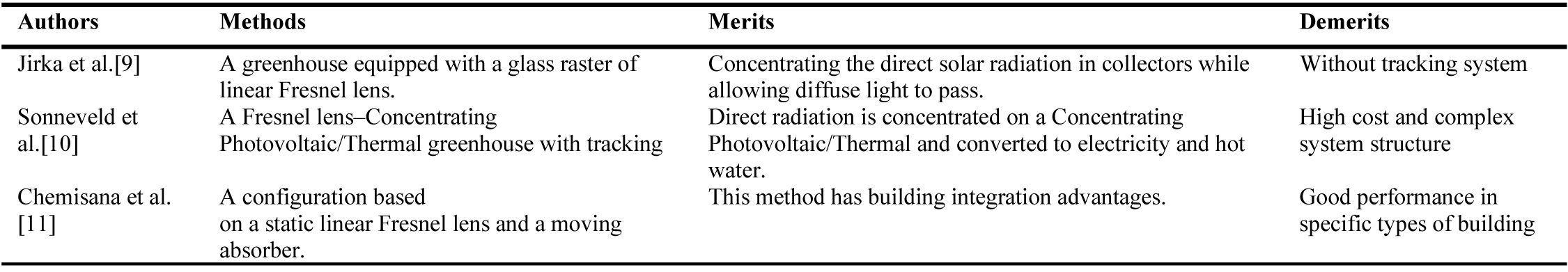
Table 1. Surface properties of building envelope elements.
In this paper, a transmission-type solar concentrated thermal/daylighting compound system for agricultural greenhouse is designed, which makes full use of the land resources in the greenhouse. Considering that not all the lights going through the plastic cover can be received and converged by crops, lights reach on to the back wall of the greenhouse is possibly be used via some other way. The system collects the surplus solar energy for power generation or heat collection, which improves the economic efficiency of the system. This part of energy irradiates to the back wall. Through the analysis of the new greenhouse, it has a good application prospect. In the following part 2, the design and modeling of solar concentrating system is introduced. Part 3 gives the analysis on heat collection and illumination.
2. Modeling of concentrating system
2.1. Working principle
The sliding-type cylindrical Fresnel lens concentrating collector for agricultural greenhouse designed in this paper will work mainly from autumn equinox to spring equinox,as shown in Fig. 1. At the same time, the width direction is X-axis, the length direction is Y-axis, and the height direction is Z-axis, so as to facilitate the subsequent analysis. Firstly, the light rays from the sun incidence on the cylindrical Fresnel lens are projected on the circular cross section (perpendicular to the generatrix of the cylindrical surface) and the circular symmetry plane respectively. As shown in Fig. 2, the included angle between the projection in the circular section and the optical axis is called the circumferential deflection angle, which is denoted as φ. The included angle between the projection in the circular symmetry plane and the optical axis is called the inclination incident angle, which is recorded as ψ. Through the Fresnel lens installed on the sliding track outside the greenhouse, the sunlight converges to the surface of the receiver placed under the lens through two refractions. The sliding of Fresnel lens is controlled by a motor to achieve zero circumferential deflection angle when sunlight irradiates the lens surface as far as possible. When the sun’s inclination incident angle is increasing, the light will not be accepted entirely by the receiver. In order to optimize the concentrating effect and concentrate the light that does not reach the surface of the receiver, a secondary concentrator is set 10 mm below the receiver. The heat energy collected by the receiver is carried away and stored underground in the greenhouse or used for power generation and heating through thermoelectric equipment. At the same time, in order to improve the space utilization rate of non-planting space, the concentrating system is placed near the back wall. The heat collection system in this position does not block the photosynthetic activity radiation of plants in the planting area, but collect a part of the direct light which would come to the north wall of the greenhouse [12].
Figure 1

Fig. 1. Structure diagram of the agricultural greenhouse with sliding-type cylindrical fresnel lens concentrating collector. (1) sliding track control system; (2) Fresnel lens; (3) vacuum tube; (4) secondary concentrator; (5) back wall; (6) power generation equipment; (7) underground heat storage equipment.
Figure 2
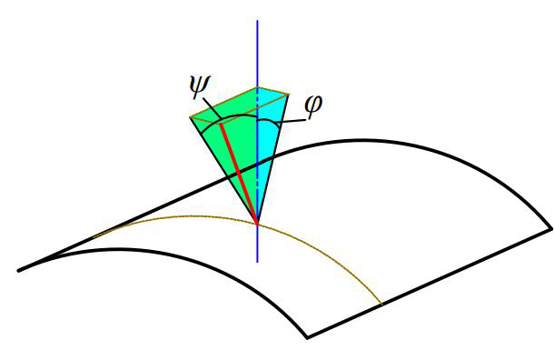
Fig. 2. Incident angle decomposition of cylindrical Fresnel lens.
2.2. Design of concentrating system
2.2.1. Design of cylindrical Fresnel lens
There are two main types of concentrators, including reflective type and transmissive type. Compared with the reflective concentrator, the transmissive Fresnel concentrator has many technical advantages, such as light weight, large transmissivity and plastic molding-making. In this design, the system only uses the energy of direct sunlight going to the back wall that is hardly to be used by plant growth. So, it has little influence on the plant growth. Under the double constraints of greenhouse size and back wall height, Fresnel lens with suitable size is selected as the primary concentrator (Fig. 3). Generally, the height of the greenhouse is about 4m, and the light width shining on the back wall is about 2-3 m. For another reason, the sunlight during winter time is always with a larger inclination angle. Therefore, the Fresnel lens with chord length 2 m is selected as the solar concentrator which barely affects the illumination on plant. Besides, the concentration ratio (the ratio of solar radiation intensity through the concentrator to the surface radiation intensity of receiver) of heat collection and power generation should be considered. Generally speaking, the larger the receiving angle is, the smaller the focusing ratio is, so the two are negatively correlated. In order to make the receiver have a larger receiving angle and have more heat collection time in a day range, the selection of focusing ratio needs to be combined with the matching of the receiver. According to the standard proposed by China Technical Committee for energy foundation and management standardization, a 100 mm diameter vacuum tube receiver is selected. Geometric concentration ratio (the ratio of the output area of the concentrator to the surface area of the receiver) of the system is 6.37. It is more reasonable under the condition of the inclination incident angle of the sun and the sunlight beam’s width reached the back wall. The focal length of the selected Fresnel lens is 1770mm. It is well known that the focal point will move up with the increase of the sun's inclination incidence angle. The placed location of receiver needs to be analyzed. By using LightTools optical analysis software, the light receiving efficiency ηrec of receiver at different distance with Fresnel lens is analyzed, which is defined as the ratio of the number of simulating rays to the number of receiving rays. By using light beam to simulate the real sunlight exposure, the light path is direct viewing and the number of received light can be obtained in LightTools. It also can be clarified as the efficiency of the receiver, which shows the capability of capturing light. As shown in Fig. 4, it can be seen that the closer the receiver is to the upper part within a certain range, the higher the average receiving efficiency and the wider receiving angle are. When the distance length is 1560 mm between Fresnel and receiver, the average receiving efficiency is the highest, and the range of the inclination incident angle is 76°.
Figure 3
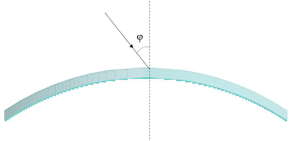
Fig. 3. Cylindrical Fresnel lens.
Figure 4
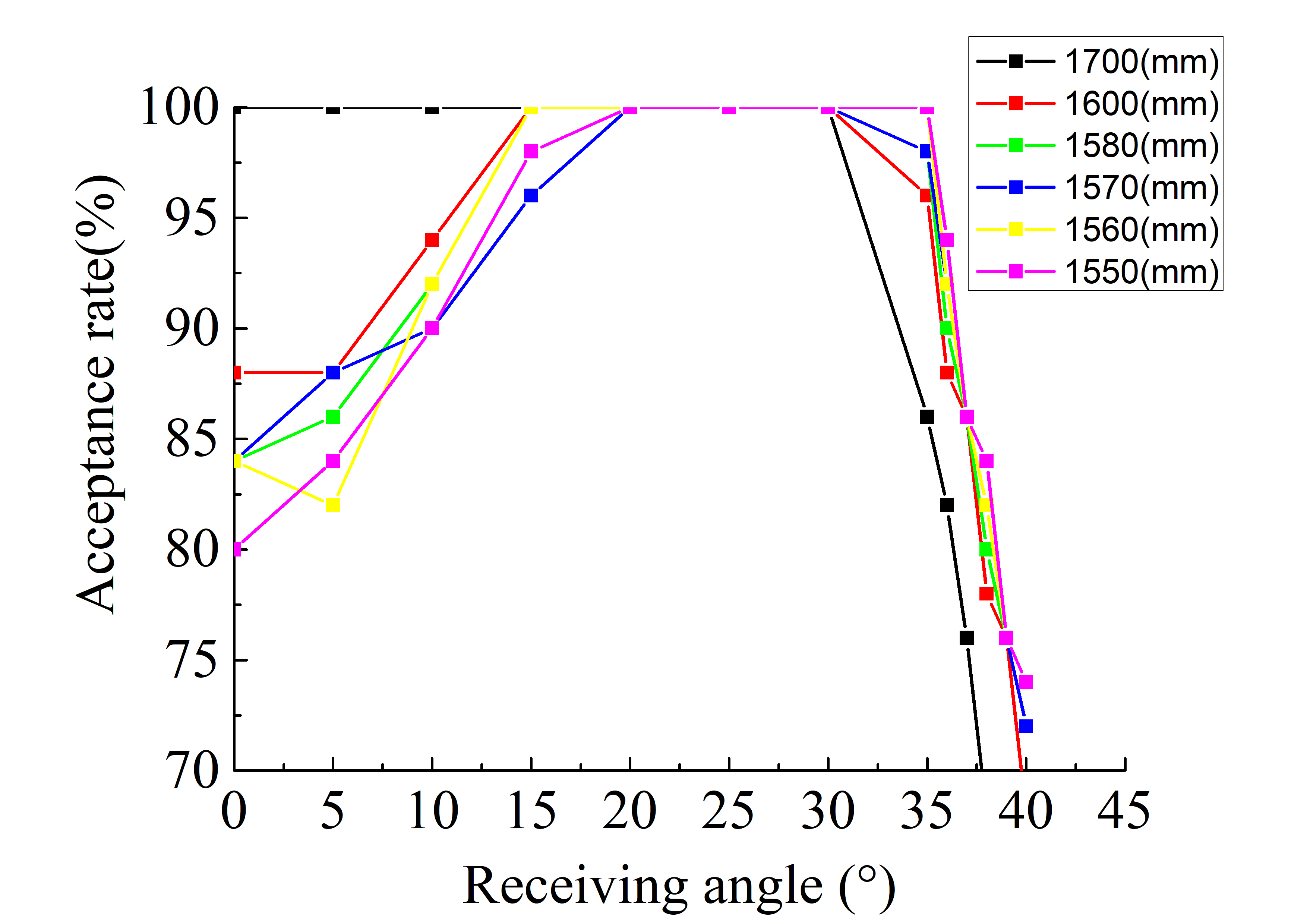
Fig. 4. Light receiving efficiency at different distance between Fresnel and receiver.
2.2.2. Analysis of ray number independence
When using LightTools optical simulation software to simulate the built model, the rays are needed to set for imitating the sunlight. Whether the number of rays has an impact on the rays’ receiving efficiency in the simulation process, and how to select the number of rays used in the simulation, the specific data could answer that. The light receiving efficiency of receiver is obtained by simulating, and the results are shown in Fig. 5. On the whole, the smaller the number of rays, the greater the error will be. Because the proportion of single ray to the total number of rays increases, the simulation results will not be accurate enough. From the graph drawn by the results, it is clear that with the increase of the number of rays, the fitting degree of the results is more accurate. But obviously, when the number of rays exceeds a certain value, the receiving efficiency curve will show a very stable trend. Therefore, as long as the light number is greater than 200, the receiving efficiency curve tends to be stable. The number of lines is not less than 50, and the deviation of receiving efficiency does not exceed 2%, which is called ray independence. So, the number of sunlight should be set no less than 1000 to make a better performance in accuracy and will not influence the operating rate.
Figure 5
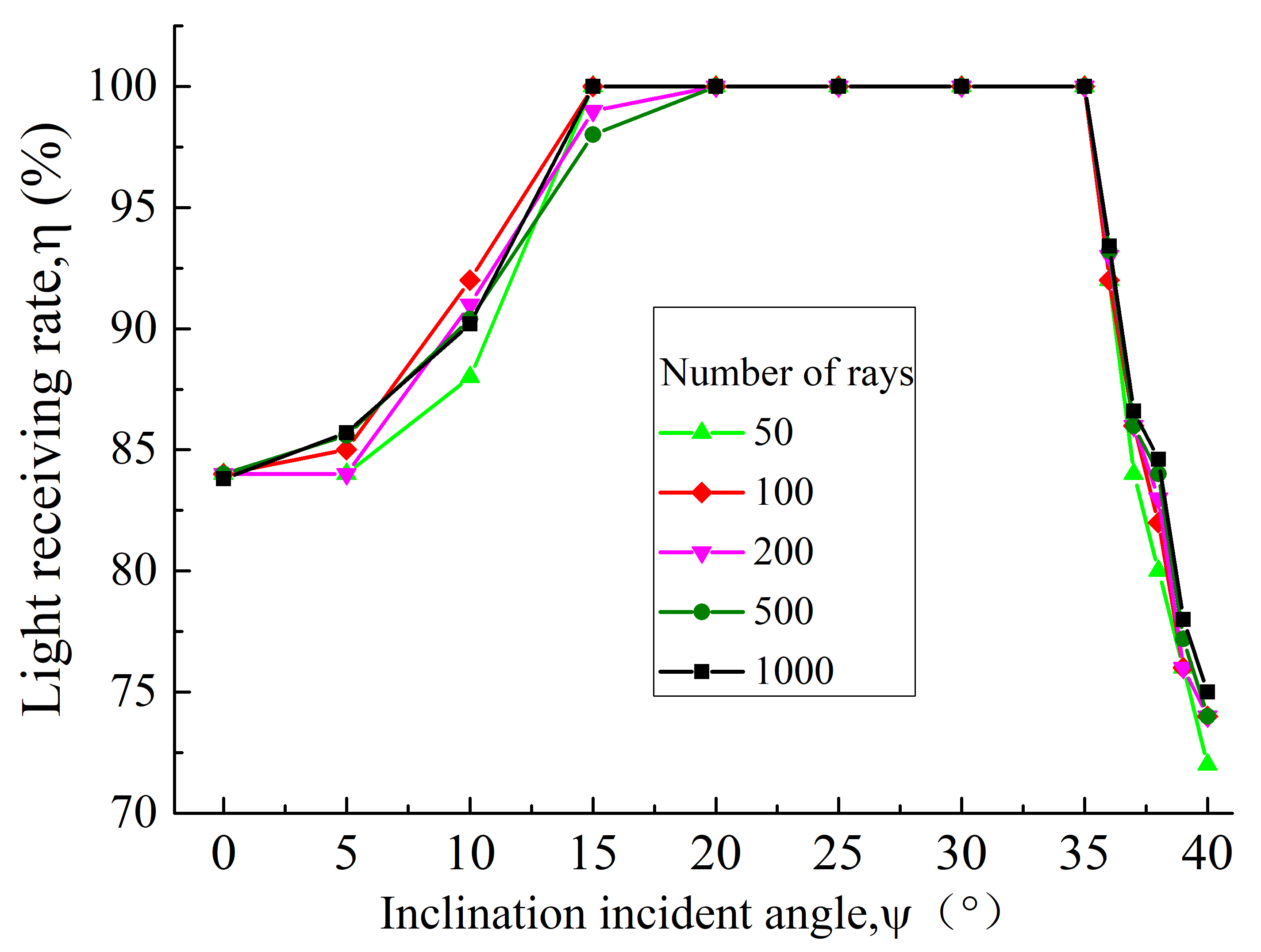
Fig. 5. Light receiving efficiency with different number of simulated rays.
2.2.3. Design of secondary concentrator
As an important component of the optical system, the secondary concentrator further enhances the focusing characteristics of the system. By converging the light in the range of inclination incident angle to the receiver again, the light gathering power is improved a lot. As shown in Fig. 6, a special-designed CPC-type reflector is selected as secondary concentrator in the system. After comparing the focusing characteristics of involute and composite paraboloid as the reflecting and concentrating surface, the basic shape of CPC is designed according to the sun’ s inclination incident angle and receiver size [14]. However, if the aperture width of CPC is too small, the width of the main mirror will be too narrow, and the energy will be reduced.
Figure 6
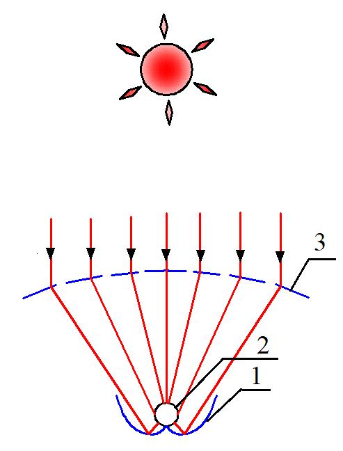
Fig. 6. Concentrating principle of secondary concentrator. (1) secondary concentrator-cpc; (2) receiver; (3) Fresnel lens.
Firstly, the base circle is determined according to the size of the receiver, and the main incident direction of the starting point of the aperture (determined by the predetermined aperture width) is resolved (which can be determined by detailed ray trajectory simulation or some analysis methods. In a simplified way, the critical incident light L1 and L2 and the receiving angle of 30° are taken as constraints). The reflection target direction points to the center of the heat absorbing tube. The surface normal direction of the starting point will be one-half of the main incident direction and the reflection target direction. Secondly, the second surface point is determined along the tangent vector of the surface by specifying the step distance (depending on the required surface accuracy). Then, the process of starting point is repeated. The main incidence, reflection, surface normal and surface tangent at the second surface point can be determined. The complete concentrator shape can be obtained by repeating the above process (Fig. 7).
Figure 7
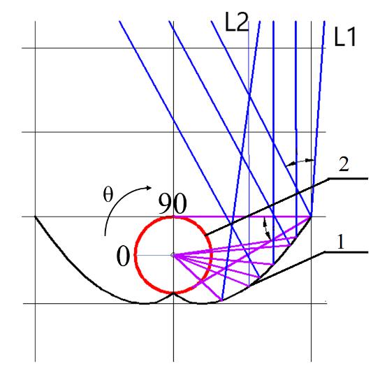
Fig. 7. Design process of secondary concentrator. (1) secondary concentrator-cpc; (2) receiver.
3. Results and discussions
In order to verify the feasibility of the design system, this paper uses SolidWorks modeling software to model each part according to the design requirements which is shown in Table 2. In simulation software, the specific solar irradiance and Fresnel lens transmittance loss are both set which bring out the following analysis results.
Table 2

Table 2. Size of the main components of the system.
3.1. Energy analysis
3.1.1. Energy distribution on the receiver surface
In order to intuitively understand the energy distribution of the vacuum tube receiver surface, through the software simulation of the designed concentrating system, the energy distribution diagram as shown in Fig. 8 is obtained. The inclination incident angle is larger when the sun rises in the morning. As the time approaching noon, the incidence angle decreases and then increases again in the afternoon. The focal spot obtained by the concentrator will move up and down. Therefore, the energy distribution is quite different under different sun inclination incidence angles. The surface of the receiver for energy analysis is expanded to a 360°circular surface, and the position of the sun's normal incidence is set at 90°, as shown in Fig. 7. At 0° normal incidence, the energy distribution is not uniform. The focal spot is located below the receiver, and the energy is reflected to the surface of the receiver by secondary concentrator. The peak valley value of energy distribution appears. The maximum energy density is 10600 W/m2, which is about tenfold to normal sunlight, as shown in Fig. 8(a). When the light deviates by 10°, the energy distribution becomes more uniform and Fig. 8(b) shows that there are only two small areas of no concentrating energy, and the maximum value of energy density is 9920 W/m2. When the light continues to shift to 20 degrees, it is obvious in Fig. 8(c) that the energy distribution becomes very concentrated. At this time, the focal spot rises near the upper surface of the receiver, which makes the energy concentrate to form a denser spot. At the same time, the maximum energy density is 23600 W/m2. When the light is shifted to 30 degrees, the energy distribution becomes even again, as shown in Fig. 8(d). At this time, the focal spot is higher than the receiver, there is no obvious energy convergence area, and the distribution is relatively scattered. Only existing the condition that the energy is zero when in the range of less than 100° circular angle, the maximum energy density is 10100 W/m2. When the light offset to the maximum edge inclination incident angle 38°of the receiver, there are two energy convergence areas and one energy blank area in Fig. 8(e). At this time, the collected energy has been significantly reduced, and the maximum value is reduced to 6530 W/m2. It is 52% less than the peak energy density of normal incidence comparing with Fig. 8(a).
By analyzing the energy distribution map of the receiver surface at different incidence angles, the best time for collecting heat is clear. Besides, it is more intuitively to see the influence of the focal spot moving up with the sun's inclination incident angle on the energy distribution of the receiver. At the same time, it paves the way for the subsequent economic analysis.
Figure 8
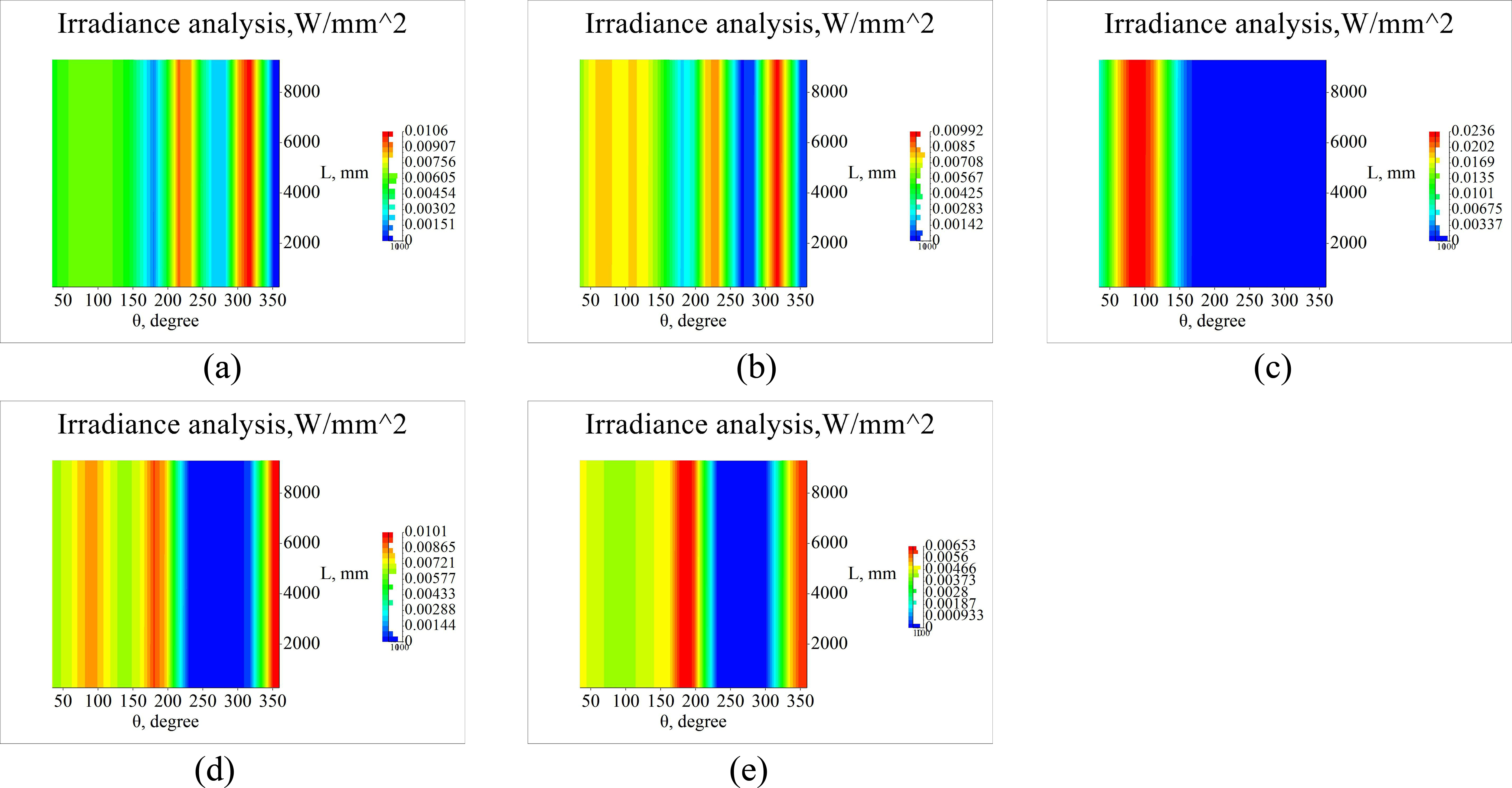
Fig. 8. Energy distribution nephogram of vacuum tube surface at (a) zero incidence angle, (b) at incidence angle 10°, (c) at incidence angle 20°, (d) at incidence angle 30°, (e) at incidence angle 38°.
3.1.2. Energy safety of the concentrating system
Sunlight incident into the greenhouse is mainly divided into photothermal environment and lighting system for plant growth. Generally speaking, the sunlight entering the greenhouse is not only direct light but scattered light, which will not affect the growth of crops due to the utilization of a certain part. However, the existence of the concentrating system, the energy is highly concentrated, which generates high temperature on the surface of the collector. In the process of incident light offset, if a small part of the light converges at the edge of the concentrator and irradiates to the outside of the receiver, whether or not it will damage crops or pedestrians, it requires energy analysis to determine the safety of the system.
According to the simulation, when the concentrating system is located above the crops, the energy deviation process is obtained. The ground energy illumination distribution between 0° and 38° is also analyzed. When the inclination incident angle is 38°, there will exist maximum local irradiance value, as shown in Fig. 9. According to the national meteorological data, the average solar irradiance in summer is 1000 W/m2. When the light cannot be received to the surface of the concentrator due to the light deviation, the maximum local irradiance will be 373 W/m2. The light gone through the concentrator’s edge will not be received by receiver and will reach to the planting area. This part of light can be seen as the leakage of the system. This part of light could increase the energy tensity of the planting area. As we can see from Fig. 9, the maximum irradiance could reach 1373 W/m2, which is about 37% higher comparing to normal incidence. Furthermore, when the light going to the north wall, the local irradiance value shining on the plants will be less. Moreover, this process lasts only a few minutes, so it would not cause harm to crops or people [15].
Figure 9
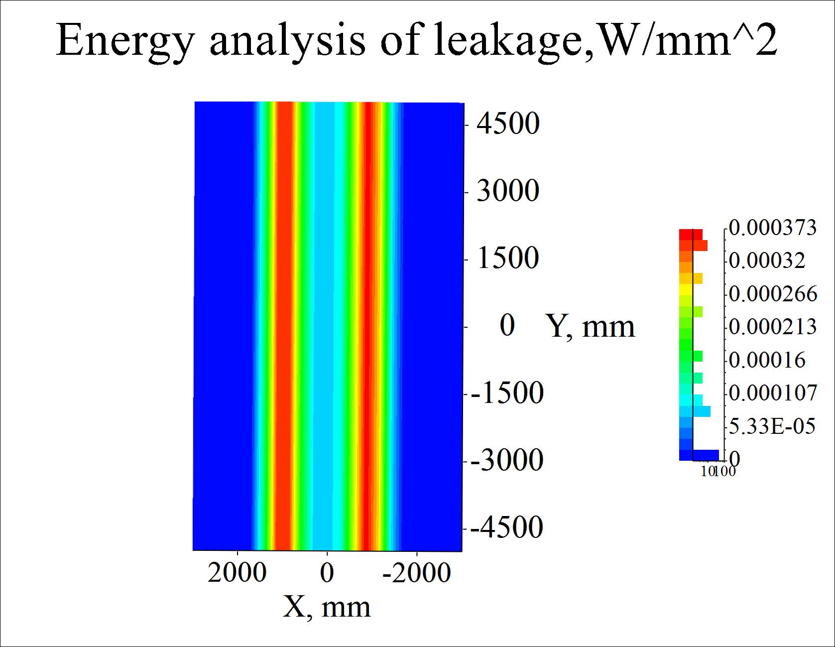
Fig. 9. Cloud image of energy flux under leakage.
3.2. Effect of concentrating system on illuminance in greenhouse
Greenhouse planting needs light environment and thermal environment, so the film materials of the greenhouse are made of materials with good transparency and heat preservation. However, the installed concentrating system will inevitably affect the plant illumination, thus changes the light environment. The analysis of the indoor brightness is done to illustrate the illumination of the system. In order to simulate the real sunlight as much as possible, the sunlight incident into the greenhouse is divided into scattered light and direct light, as shown in Fig. 10. According to the general distribution of illumination energy, the irradiance of scattered light in the greenhouse is 400 W/m2 and that of direct light is 600 W/m2. The results shown in Figs. 11 and 12 are obtained. The illumination distribution on the ground can reach 8.38×10⁵ Lux, and the lowest can reach 4.22×10⁵ Lux. Figure 12 shows the distribution of illumination on the rear wall, with the highest illumination reaching 7.62×10⁵ Lux, and the lowest value reaching 3.05×10⁵ Lux. According to Umberto Berardi [16] and Ignacio García [17], when the indoor illumination reaches 2000 Lux, it can realize normal activities under human vision. When it exceeds 105Lux, it is close to the illuminance under direct sunlight outside the greenhouse. Therefore, setting up a concentrating system outside the greenhouse will not affect the indoor light environment, and will have little impact on the indoor illumination.
Figure 10
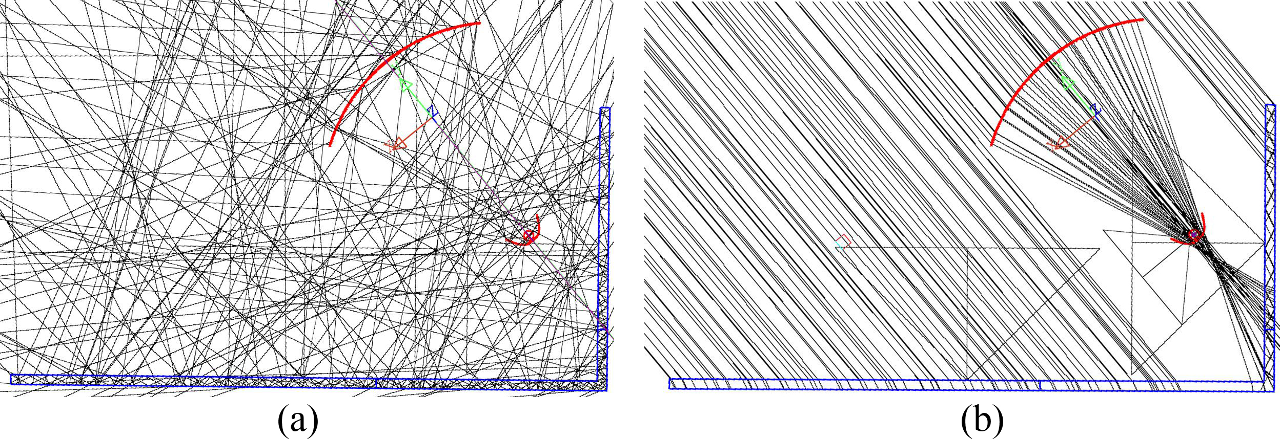
Fig. 10. (a) Scattered and (b) direct light.
Figure 11
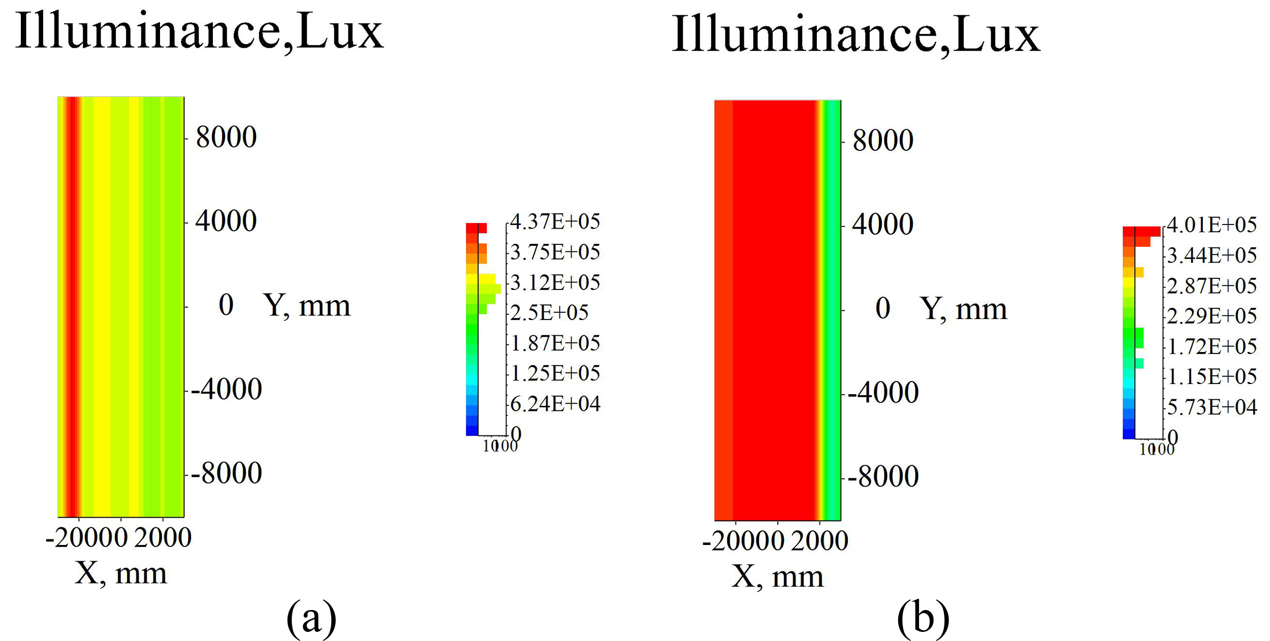
Fig. 11. Ground illuminance of greenhouse (a) scattered light of 40% sunlight and (b) direct light of 60% sunlight.
Figure 12
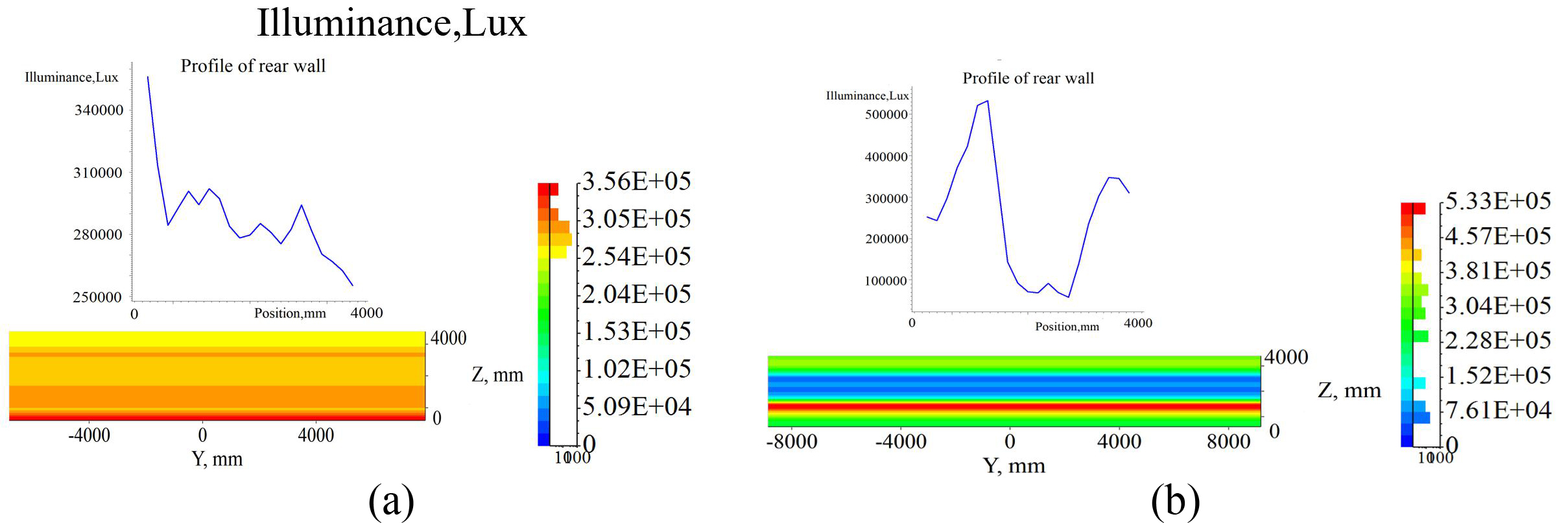
Fig. 12. Rear wall illuminance of greenhouse (a) scattered light of 40% sunlight and (b) direct light of 60% sunlight.
3.3. Effect of tracking error angle on receiving efficiency
The sliding Fresnel lens on greenhouse needs tracking the sun to keep high collection efficiency. The above analysis in this paper is based on zero tracking error angle. However, the real-time tracking of slip orbit and control is not error-free. If the solar altitude angle cannot be guaranteed to be zero degree without error due to the hesitation or jamming in the sliding process, it will have an impact on the solar receiving efficiency. Therefore, it is necessary to analyze the influence of the tracking error angle on the ray receiving efficiency. The ray receiving efficiency is obtained by changing the height angle of the light in the simulation software to simulate the influence on the ray reception when the tracking error occurs. The simulation results are shown in Fig. 13. When the tracking error angle is less than 1°, the ray receiving efficiency can still ensure more than 95% efficiency. But when the tracking error angle exceeds 1°, the decline rate of the receiving efficiency increases obviously. When the tracking error angle exceeds 1.5°, the receiving efficiency has dropped to 90%. As long as the tracking error is no more than 2°, the efficiency of the concentrating system can reach 80% at least. Due to the chord length of Fresnel is 2000 mm, the 2° is a large range relatively. In addition, in the design of sliding greenhouse, it is necessary to have a high precision tracking ability to ensure that the concentrating efficiency of the concentrating system is not affected.
Figure 13
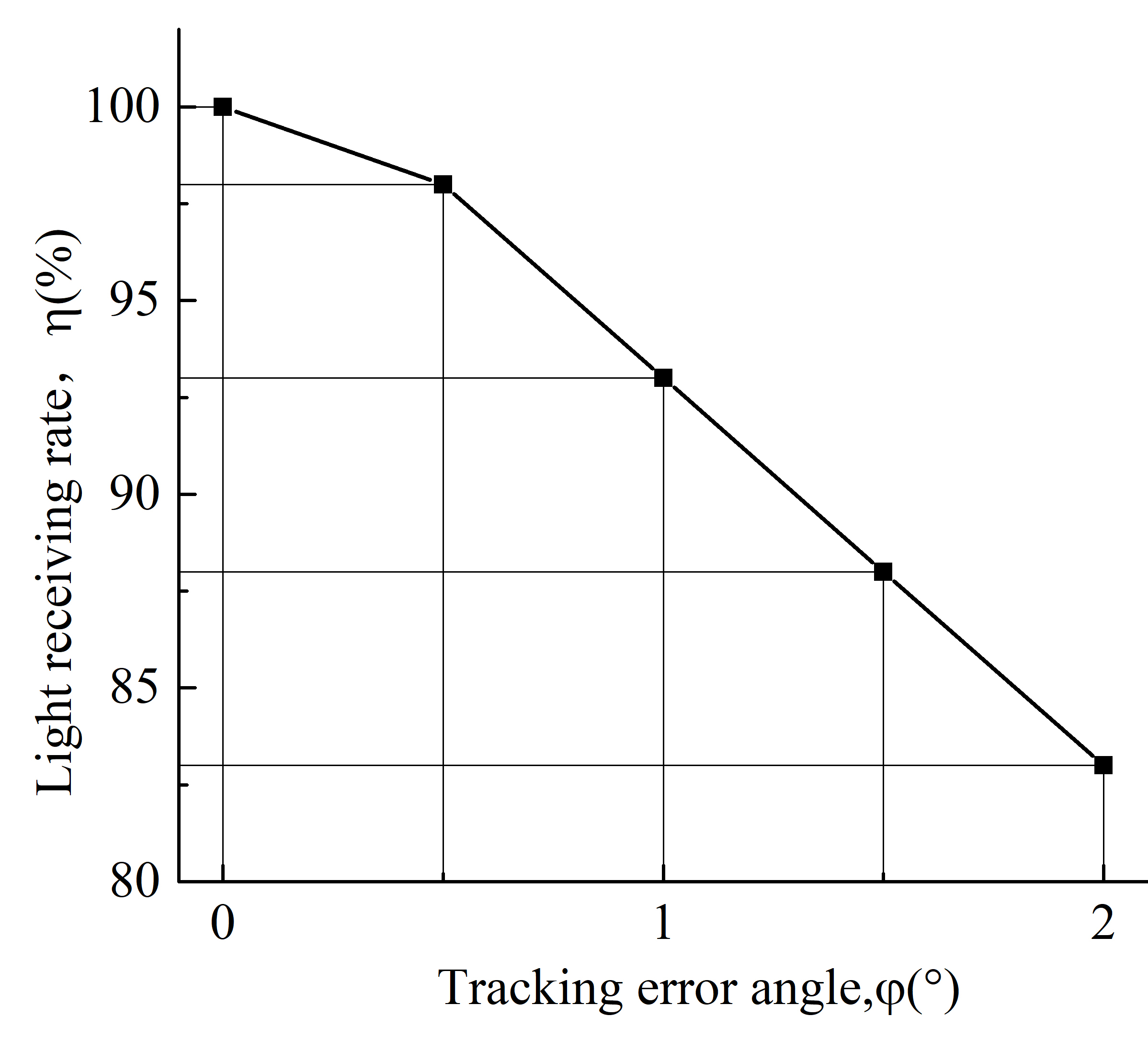
Fig. 13. Variation of the light receiving efficiency with tracking error angle.
3.4. Analysis of energy gains
According to the real solar irradiance, the incident energy is designed in software. While the light cannot be fully captured by the receiver, due to the transmittance loss of the concentrator, and the surface receiving rate of the receiver, the loss of secondary reflector, etc. The energy receiving rate shows the heat-collection capability of system by considering the energy loss and transmissivity, which is denoted as collection efficiency ηc. That is a problem that the collection efficiency ηc cannot reach 100%. Besides, the solar energy density is low. So, the energy obtained by receiver needs to be analyzed. By dividing the surface of the receiver into 21×21 grids distribution, the total energy Iabs received on the surface is calculated, as Eq. (1).
where Ea is the average solar radiation energy on the surface of receiver, and Sr is the area of the receiver.
Given the set irradiance of 1000 W/m2, the total input energy Ie is calculated, as Eq. (2).
where E is the set irradiance with the value of 1000 W/m2, S is the surface area of light source.
The collection efficiency ηc of the receiver is given as:
The change of collection efficiency under different inclination incident angles is shown in Fig. 14. It can be seen from the figure that when the inclination incident angle is less than 20°, the collection efficiency increases continuously from the normal incidence of light to the 20° inclination incident angle. This is due to the increasing of the sun's incident angle, the focal spot moves up, making more light focus on the receiver at the position where it is placed. When the sun's incident angle exceeds 30°, the collection efficiency decreases rapidly. The average collection efficiency is 80% in the range of inclination incident angle of 76° by calculation, so the whole energy receiving process matches the result of light receiving. The receiving efficiency in the range of - 38° to 38° inclination incidence angle is also valuable and higher than 80%.
Figure 14

Fig. 14. Collection efficiency at different inclination incident angle.
Taking Beijing, China as an example, according to China's meteorological data [18], the average daily irradiance in the six months from September to February of one year is shown in Fig. 15. Due to the influence of sunshine time and weather, the average radiation intensity is relatively stable. The greenhouse designed in this paper is 80 meters in depth, 6 meters in width and 4 meters in height. The design chord length of Fresnel lens is 2 m, so the receiving area is 160 m2. According to the calculation, the total radiation energy obtained in six months is 377568.8 MJ, as Eq. (4).
Figure 15
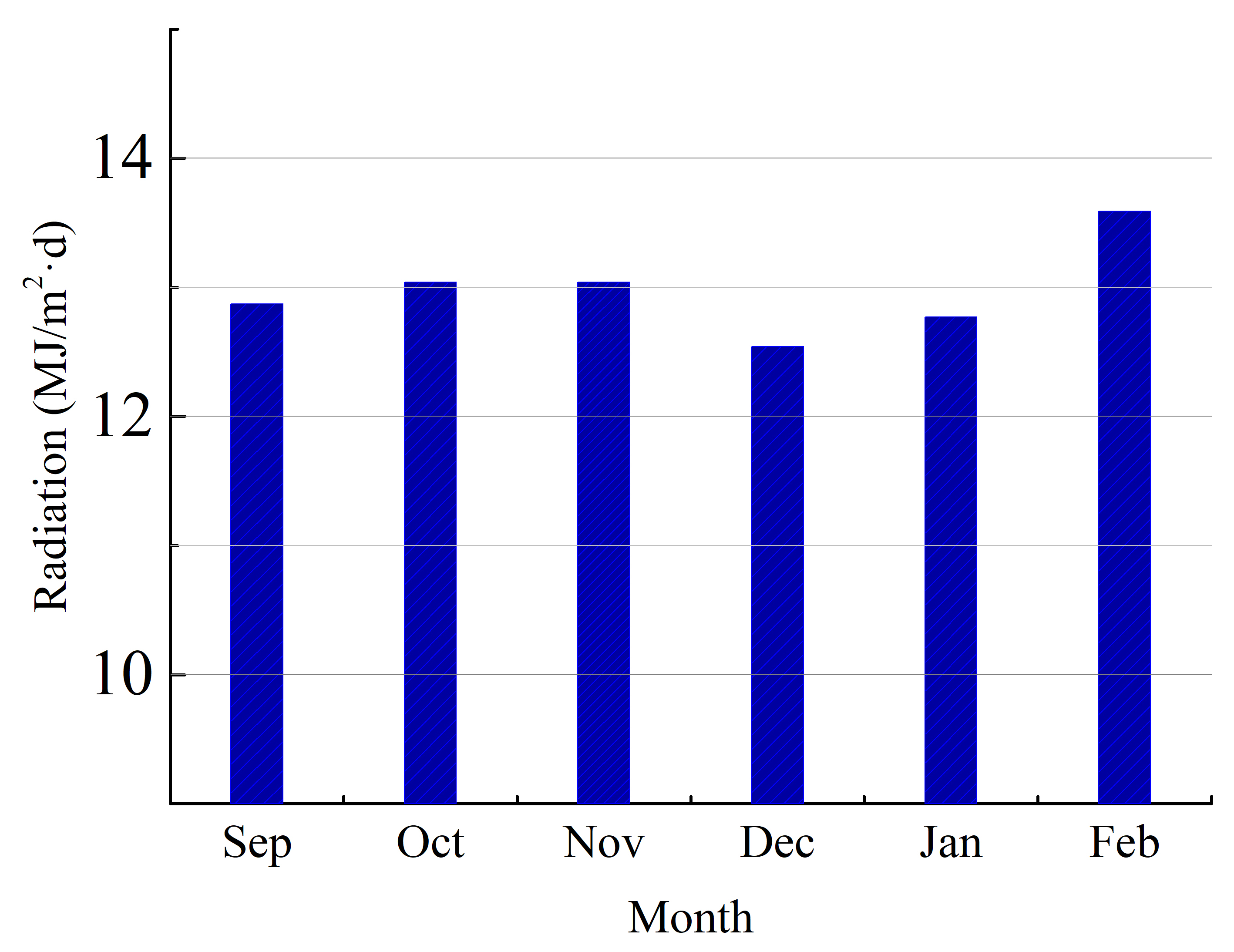
Fig. 15. Daily average irradiance in different months in Beijing, China.
where Ie is the calculated energy, which is going through the concentrator according to usual real solar irradiance data, I is the product of real daily mean solar irradiance in Beijing and the receiving area of greenhouse. D is the days of every month.
This part of energy enters the system and is used for greenhouse heating. According to the transmission efficiency and energy loss, the energy received by the receiver is 302055 MJ, which is given as Eq. (5).
The calorific value of national standard coal used in traditional coal-fired heating is 29.27 MJ/kg, so the energy obtained by the solar energy collection system is equivalent to 10319.6 kg standard coal, as Eq. (6).
where Wcoal is the equivalent standard coal weight, and Is-coal is the calorific value of standard coal.
If electric energy is considered for heating that 1 kg coal can generate 8.13 kW·h of electric energy, so this part of heat is equivalent to 83898.4 kW·h of electric energy, which is given as:
where Ep is the electric power.
And 1 kW·h of electricity on the market is about $0.074, which will save $6153.9 of electricity, as shown in Table 3.
Table 3

Table 3. Energy equivalent graph of system saving.
4. Summary
4.1. Conclusion
By modeling and analyzing a sliding-type cylindrical Fresnel lens concentrating system, we find that when the inclination incident angle of the sun is 20°, the maximum local energy density of the receiver surface is 23600 W/m2. The receiver is located below the focus of Fresnel lens of 210 mm. If the light leak exists, there would be 37% higher than the normal ground energy distribution. So, there is no high-temperature damage to crops. The illumination in the greenhouse is also counted for lighting environment. It is found that the illumination range is from 4.22×10⁵ Lux to 8.38×10⁵ Lux on the ground. The illumination range is from 3.05×10⁵ Lux to 7.62×10⁵ Lux on the wall. So, the concentrating system has little effect on the light environment in the greenhouse. According to the formula of collection efficiency, we obtain that the collection efficiency of the system is higher than 80% in the range of 0° to 38° solar inclination incidence angle. By obtaining the daily average solar irradiance data in Beijing, we get the energy benefit of the concentrator system in autumn to winter. This part of energy used for greenhouse heating is equivalent to spending 6153.9 $ of electric energy for heating. Therefore, the energy benefit of the concentrating system is considerable.
4.2. Application prospect
We designed a sliding-type cylindrical Fresnel lens concentrating collector for an agricultural greenhouse, not only can energy be used efficiently but the land utilization rate can be improved. It realizes the "agricultural and optical complementation" efficiently. Combining agricultural planting with solar energy collection and power generation has a very valuable development prospect, especially for some remote areas with high latitude. It is used for greenhouse insulation in cold winter, and can be used for power generation in sunny summer. The output can both face to greenhouse and customers.
Generally speaking, solar energy collection system can be used in many engineering systems, such as desalination or power generation. For some areas closing to the coastal or inland areas where water shortage is scarce, heat can be used for desalination of seawater or brackish water for agricultural irrigation.
4.3. Future work
Greenhouse itself is a facility to use solar energy, but there is still a part of the energy that is not effectively used. There is still a large space for the development of solar thermal technology in greenhouse. Two major problems are as follows. The first is the low efficiency of heat collection. Due to the influence of traditional solar energy collection methods (such as trough and flat plate), the heat collection area is very limited. It is difficult to meet the requirements of greenhouse heating at night in winter. The second is insufficient heat preservation and uneven indoor illumination. Due to the structure of greenhouse itself, the difference of light intensity is large.
Therefore, the innovation of this paper is mainly to solve the first kind of problems. Combining the transmission and heat collection or power generation technology with modern new agricultural engineering, a new energy-saving idea based on Fresnel lens is put forward. It builds a sliding track to track the concentrating light in the greenhouse coverage. The advantages of the system are to improve the utilization efficiency of greenhouse space, and obtain the high efficiency and low cost of the overall system. This operation mode is not only a new energy project, but also an interdisciplinary subject. The concept of complementary agriculture and light has good innovation. However, there is no research and optimization of agricultural greenhouse covering materials. In the follow-up research process, this aspect can be considered in the greenhouse design to build a more optimized new agricultural greenhouse.
In addition, the primary concentrator is not a large-scale Fresnel lens, so the receiving angle is small. The inclination incidence angle of the sun designed in this paper is only 76° and can only meet the high-efficiency heat collection of 5-6 hours under normal sunlight conditions. The energy obtained is mainly used for greenhouse heat preservation and heat storage. If more generated electricity needs to be transported to users, a larger concentrating and heat collecting system is needed to be re-designed. That is to say, the large-scale commercial agricultural greenhouse is the future development direction and work goal.
Acknowledgment
This work is supported by the National Science Foundation of China (No.51976013).
Contributions
The simulation and writing work of this paper are completed by Q. He. The idea behind this work is provided by H. Zheng. The simulation work of this paper is completed under the guidance of X. Ma and G. Wang.
Declaration of competing interest
The authors report no conflicts of interests.
References
- A.T. Le, L. Wang, Y. Wang, Measurement investigation on the feasibility of shallow geothermal energy for heating and cooling applied in agricultural greenhouses of Shouguang City: Ground temperature profiles and geothermal potential, Information Processing in Agriculture. https://doi.org/10.1016/j.inpa.2020.06.001
- G.Wu, Z.Yi, Energy and optical analysis of photovoltaic thermal integrated with rotary linear curved Fresnel lens inside a Chinese solar greenhouse, Energy 197 (2020) 117-215. https://doi.org/10.1016/j.energy.2020.117215
- C. Lamnatou, D. Chemisana, Solar radiation manipulations and their role in greenhouse claddings: Fresnel lenses, NIR- and UV-blocking materials, Renewable and Sustainable Energy Reviews 18 (2013) 271-287. https://doi.org/10.1016/j.rser.2012.09.041
- A.Marucci, A.Cappuccini, Dynamic photovoltaic greenhouse: Energy efficiency in clear skyconditions, Applied Energy 170 (2016) 362-376. https://doi.org/10.1016/j.apenergy.2016.02.138
- O.Rabhy, I.G.Adam, Numerical and experimental analyses of a transparent solar distiller for an agricultural greenhouse, Applied Energy 253 (2019) 113564. https://doi.org/10.1016/j.apenergy.2019.113564
- N.Luca La, G.Lorena, C.Emanuele, Hybrid and organic photovoltaics for greenhouse applications, Applied Energy 278 (2020) 115582. https://doi.org/10.1016/j.renene.2018.08.075
- L.Gourdo, H.Fatnassi, R.Tiskatine, Solar energy storing rock-bed to heat an agricultural greenhouse, Energy 169 (2019) 206-212. https://doi.org/10.1016/j.energy.2018.12.036
- R.C.Allil et al, Solar tracker development based on a POF bundle and Fresnel lens applied to environment illumination and microalgae cultivation, Solar Energy 174 (2018) 648-659. https://doi.org/10.1016/j.solener.2018.09.061
- V.Jirka, V.Kuceravy, M.Maly, F.Pech, J.Pokorny, Energy flow in a greenhouse equipped with glass raster lenses, Renewable Energy 16 (1999) 660–664. https://doi.org/10.1016/s0960-1481(98)00247-x
- PJ. Sonneveld, J. Campen et al, Performance of a concentrated photovoltaic energy system with static linear Fresnel lenses, Solar Energy 85 (2011) 432–442. https://doi.org/10.1016/j.solener.2010.12.001
- D.Chemisana, C.Lamnatou, Y.Tripanagnostopoulos, Fresnel Solar Concentrators for Agriculture Applications, in: International Conference of Agricultural Engineering CIGR-AgEng2012, July 8–12, 2012b, Valencia, Spain.
- C.Chen, N.Yu, F.Yang et al, Theoretical and experimental study on selection of physical dimensions of passive solar greenhouses for enhanced energy performance, Solar Energy 191 (2019) 46-56. https://doi.org/10.1016/j.solener.2019.07.089
- X.Ma, R.Jin, S.Liang et al, Analysis on an optimal transmittance of Fresnel lens as solar concentrator, Solar Energy 207 (2020) 22-31. https://doi.org/10.1016/j.solener.2020.06.071
- G.Wu, Q.Yang, H.Fang et al, Photothermal/day lighting performance analysis of a multifunctional solid compound parabolic concentrator for an active solar greenhouse roof, Solar Energy 180 (2019) 92-103. https://doi.org/10.1016/j.solener.2019.01.007
- S.Algarni, S.Mellouli, T.Alqahtani et al, Experimental investigation of an evacuated tube solar collector incorporating nano-enhanced PCM as a thermal booster, Applied Thermal Engineering 180 (2020) 115831. https://doi.org/10.1016/j.applthermaleng.2020.115831
- Umberto, Berardi, Hamid et al. Analysis of the Impacts of Light Shelves on the Useful Daylight Illuminance in Office Buildings in Toronto, Energy Procedia 78 (2015) 1793-1798. https://doi.org/10.1016/j.egypro.2015.11.310
- I.García et al, Proposal and evaluation of typical illuminance year (TIY) generation procedures from illuminance or irradiance data for daylight assessment in the long term, Solar Energy 205 (2019) 496-511. https://doi.org/10.1016/j.solener.2020.05.083
- China Meteorological Administration, http://www.cma.gov.cn/.
Copyright © 2021 The Author(s). Published by solarlits.com.

2196
Total views
Citations
SHARE ON


