Volume 9 Issue 2 pp. 164-176 • doi: 10.15627/jd.2022.13
Daylight Performance of the Modified Double Light Pipe (MDLP) Through Experimental Analysis on a Reduced Scale Model
Paolo Zazzini,a,* Alessandro Di Crescenzo,a Roberto Giammicheleb
Author affiliations
a Department INGEO, University “G. D’Annunzio”, Viale Pindaro 42, 65127 Pescara, Italy
b Engineer, Via A.Gramsci n°10/A, Vasto (CH), Italy
*Corresponding author.
zazzini@unich.it (P. Zazzini)
dicrescenzo.a@live.it (A. Di Crescenzo)
robertogiamm.rg@gmail.com (R. Giammichele)
History: Received 21 June 2022 | Revised 30 July 2022 | Accepted 8 August 2022 | Published online 6 September 2022
Copyright: © 2022 The Author(s). Published by solarlits.com. This is an open access article under the CC BY license (http://creativecommons.org/licenses/by/4.0/).
Citation: Paolo Zazzini, Alessandro Di Crescenzo, Roberto Giammichele, Daylight Performance of the Modified Double Light Pipe (MDLP) Through Experimental Analysis on a Reduced Scale Model, Journal of Daylighting 9 (2022) 164-176. https://dx.doi.org/10.15627/jd.2022.13
Figures and tables
Abstract
This paper is focused on the Modified Double Light Pipe (MDLP), an innovative daylighting system set up by the authors in the Laboratory of Technical Physics of the University “G. D’Annunzio” of Pescara (Italy). It is an evolution of the Double Light Pipe (DLP), designed by the authors to distribute natural light in two underground levels of a building and tested through an experimental activity on a reduced scale model. The MDLP has been designed by modifying the same scale model of the DLP with the goal to solve some problems related to its size and the risk of glare, thanks to its smaller encumbrance, and a light shelf applied around the external tube to prevent the occupants of the room from seeing the upper brightest portion of the device. Furthermore, the light shelf reflects light towards the ceiling spreading it more uniformly on the horizontal work-plan. The technological components of the MDLP are shown demonstrating the possibility of installing it in both new and refurbished buildings. Then, the first results of an experimental activity carried out on the model of the MDLP in winter climatic conditions are shown. Although the unfavorable values of external illuminance, the MDLP contributes to distributing natural light in the passage room both with overcast and clear sky conditions. On sunny days, direct solar radiation hits the measure positions on the corners of the room producing peak illuminance values. The illuminance uniformity is calculated according to the EN 12464-1. The results can be considered satisfactory both in terms of internal illuminance and uniformity of light distribution.
Keywords
Daytime, Alertness, Non-visual photoreception, Lighting
1. Introduction
Natural light can give a contribution to guaranteeing visual comfort conditions in buildings [1], even if it involves the risk of some discomfort conditions due to visual glare or veil reflections. Tabadkani et al. [2] have recently underlined the role of facades equipped with daylight sources (windows) and daylighting strategies able to block or redirect light to get visual comfort condition of the occupants and analyzed a great number of parameters to underline the influence of daylight on visual comfort of occupants.
Visual comfort in internal areas of buildings depends on various physical aspects such as light quantity, absence of glare phenomena, uniformity in illuminance and luminance distribution, and adequate view outdoor, as well as psychological factors that influence the occupants’ perception of daylight [3,4].
The presence of daylight is particularly important in office buildings, as underlined by Galasiu and Veitch [5], so much that it can have a positive influence on productivity, as shown by De Carli et al. [6].
Recent studies published by IEA SHC Task 61 show that combing daylight with LED ceiling panels able to tune light colour during the day increases the office workers’ alertness [7], as well as improves the satisfaction of customers of shopping centers [8].
Daylight in buildings is very significant also for sanitary purposes. The lack of daylight can severely penalize human health, producing modification of the circadian rhythms, weakening of the immune system, alteration of mood, and depression [9,10].
Natural light also allows effective energy savings in buildings, thanks to less use of artificial light, taking into account that about 14% of electrical consumption in EU and 19 % in the world is due to the use of artificial light. [11-18]
In many cases, particularly in public buildings, this is partially due to the occupants’ bad habit of using artificial light also in presence of natural light taking curtains or blinds shut to avoid glare from the windows hit by direct solar radiation [19].
The electric energy consumption in Europe must be significantly reduced as requested by the European Directives that fixed the Nearly Zero Energy target for buildings and daylight can effectively contribute to achieving this.
For these reasons, the use of natural light in buildings is growing in importance. In this perspective, numerous visual comfort metrics have been proposed to quantify the daylight availability in the design process of buildings and thus guide the design choices [20].
When traditional sources of daylight are absent, such as in underground areas of buildings, or unable to provide an adequate light level, such as in large plan area environments (i.e. industrial or commercial buildings), daylight can be introduced and transported by technological light transport systems. Among these, light pipes or similar technological devices are very widespread [21-23]. Obradovic and Matusiak [17] propose “a literature study of daylight transport systems aiming at selecting the most appropriate ones for application at high latitudes”.
Although vertical light pipes and similar daylighting strategies are most suitable at high latitudes, being particularly apt to catch zenithal light, and less effective in the Mediterranean latitudes as suggested by Obradovic and Matusiak [17,18], these systems can still contribute to energy saving by allowing underground or basement environments to be illuminated with daylight.
In environments equipped with windows, an uneven spatial distribution of natural light usually occurs, with very high values near the window rapidly decreasing away from it. In these cases, light shelves can be effectively used to improve the spatial distribution of light [24-30].
Many authors have investigated the performance of daylighting technological devices through numerical or experimental methods [31-39].
Experimental data can be collected under real or artificial sky, using the scale model approach. Boccia and Zazzini [40] propose a critical analysis of the use of the scale model approach, underlying its simplicity and effectiveness but its reduced accuracy due to some accidental factors, such as the presence of direct solar radiation.
In previous years, the authors of this paper carried out research activities on daylight transport systems and they developed an innovative device called Double Light Pipe (DLP). The DLP is an evolution of the traditional light pipe, particularly suitable for large showrooms or museums, able to illuminate contemporarily two levels of underground buildings or buildings not equipped with traditional daylight sources [1,41].
Recently, they developed the idea of combining the technology of the DLP with that of light shelves and they set up a new system named Modified Double Light Pipe (MDLP), a technological device designed to reduce the encumbrance and the brightness of the Double Light Pipe [42].
In this paper, the authors present the technological components of the MDLP and the first results of an experimental analysis carried out on a 1:2 scale model of the system.
2. The Modified Double Light Pipe (MDLP)
The MDLP has been designed to remove some defects of the DLP, a device developed by the authors to distribute natural light in underground buildings. The authors carried out a numerical and experimental analysis on a 1:2 scale model of the DLP [1]. It can light two hypogeal levels by two coaxial tubes. The internal one brings natural light into the second underground level as a traditional light pipe, while the external transparent one allows the light to enter the intermediate room. The DLP presents some troubles: it has a considerable encumbrance and involves the risk of glare from the upper portion of the system. Moreover, it produces an uneven distribution of light, more concentrated near the tube. The illuminance values on a horizontal work-plan in the passage room decrease from the center to the corners and the upper portion of the system is very bright. This leads to a high risk of visual glare, as shown in Baroncini et al. 2010.
Starting from these considerations, the authors decided to modify the 1:2 scale model of the DLP with the intent to solve these problems and they named this new device MDLP.
The DLP has been modified by fixing to the ceiling a reflecting panel and equipping it with a circular light shelf, 600 mm distant from the ceiling, able to reflect light toward the ceiling and improve the uniformity of light distribution in the environment. The light shelf also prevents the occupants from seeing the upper portion of the device with the highest luminance, avoiding the risk of glare. Furthermore, the encumbrance of the external pipe is significantly reduced than in the DLP, because the lower portion of the tube is cut.
Figure 1
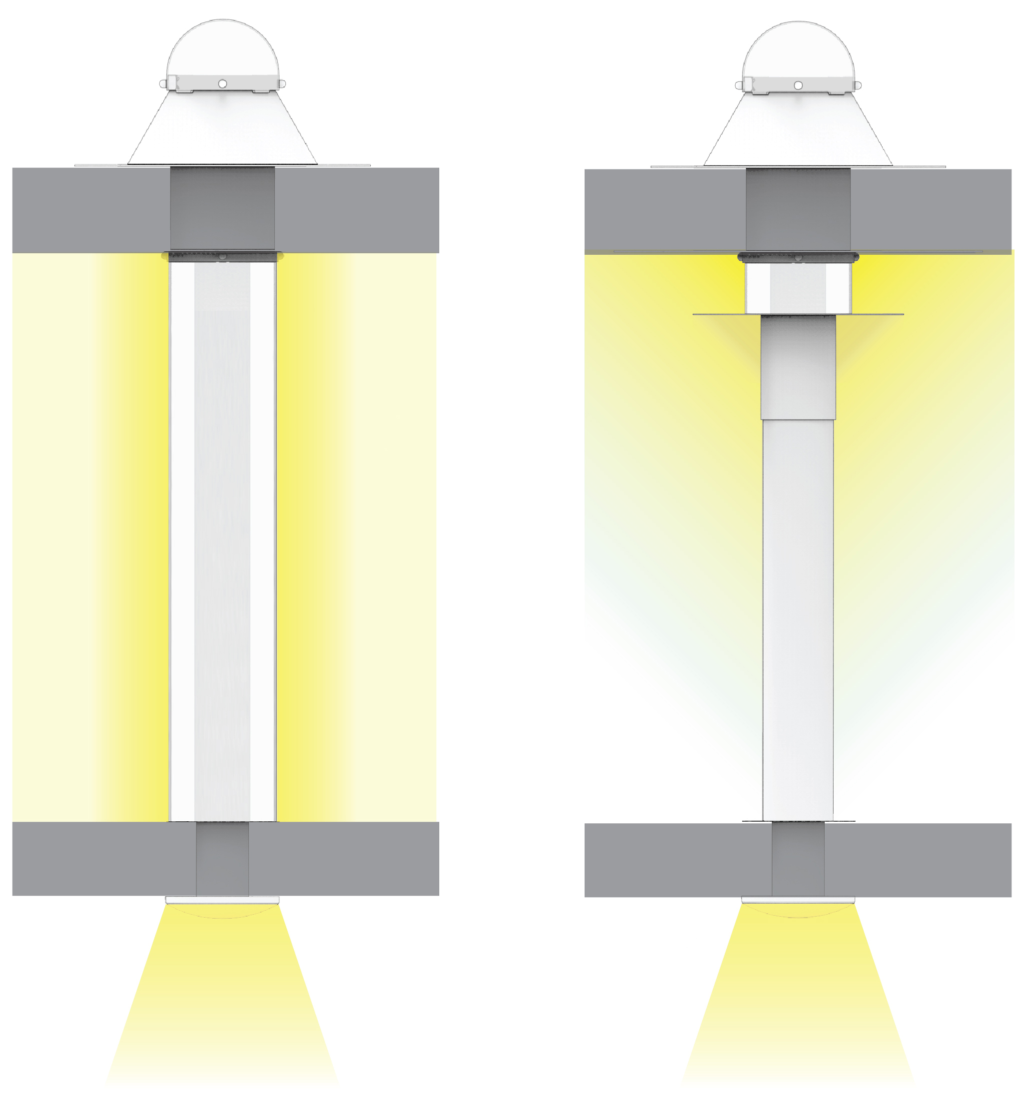
Fig. 1. Comparison between the features of (a) the DLP and (b) the MDLP.
Figure 1 shows a comparison between the DLP (Fig. 1(a)) and the MDLP (Fig. 1(b)), underlying the different visual perceptions of the two devices, and the reduced encumbrance of the MDLP if compared to the DLP.
A similar idea has been proposed in Garcia-Hansen, Edmonds [43], where the results of a study on a vertical light pipe that illuminates five levels of a building are shown. This interesting system is more complex than that illustrated in this paper. It consists of an alternation of transparent and opaque parts and, at each level, it is equipped with a partially transparent and partially reflective cone, as well as a light shelf that reflects towards the ceiling solar radiation coming from the sun with low elevation angle.
The MDLP is a simpler system, having been designed to illuminate only two underground levels. The central tube is completely opaque and coated both internally and externally with highly reflective film, while the external one is completely transparent. Moreover, the light shelf is smaller in size as it has been designed mainly to reduce the risk of glare, even if experimental tests carried out in spring and summer, whose results are not shown in this paper, demonstrated that it helps to reflect light coming from the sun with high elevation angle. Figure 2 shows all the steps that led to the construction of the system and the definition of its components as well as the method used to determine its performance.
Figure 2
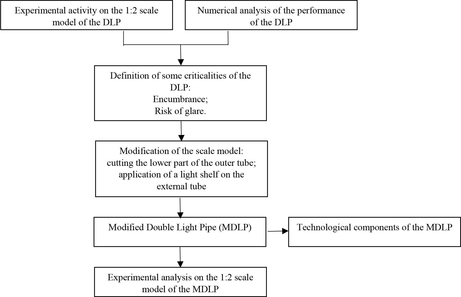
Fig. 2. Sequence of the steps that led to the creation of the MDLP and the determination of its performance.
3. Technological components and installation procedure of the MDLP
The MDLP consists of the following components:
- 500 mm diameter light collector positioned on the flat roof of the building;
- 500 mm diameter outer tube of transparent polycarbonate with a length equal to the depth of the attic plus 600 mm;
- 250 mm diameter inner tube internally and partly externally coated with a highly reflective film;
- 140 mm diameter circular reflector panel applied on the ceiling;
- 100 mm diameter light shelf, 60 mm distant from the ceiling.
The MDLP can be installed in both new and existing buildings. In this paragraph, the authors describe the device applied to a generic brick concrete roof slab as it is the most used in common constructions.
The first step of the installation process consists in making a hole over the roof slab. It must have a 505 mm diameter to allow easy fixing of the external tube. In the case of an existing building, the hole should be positioned so that only one joist is removed and an appropriate stiffening should be created to restore the structural continuity offered by the joist.
At this point, the fixing surface should be prepared by removing part of the surface layer to “hook” the flashing to the covering screed (Fig. 3). The flashing should be fixed on the screed by mechanical anchors, which allow a firm grip and high resistance thanks to friction and shape. The fixing of the flashing should be carried out using sealants and sheaths to avoid long-term corrosion phenomena.
Figure 3
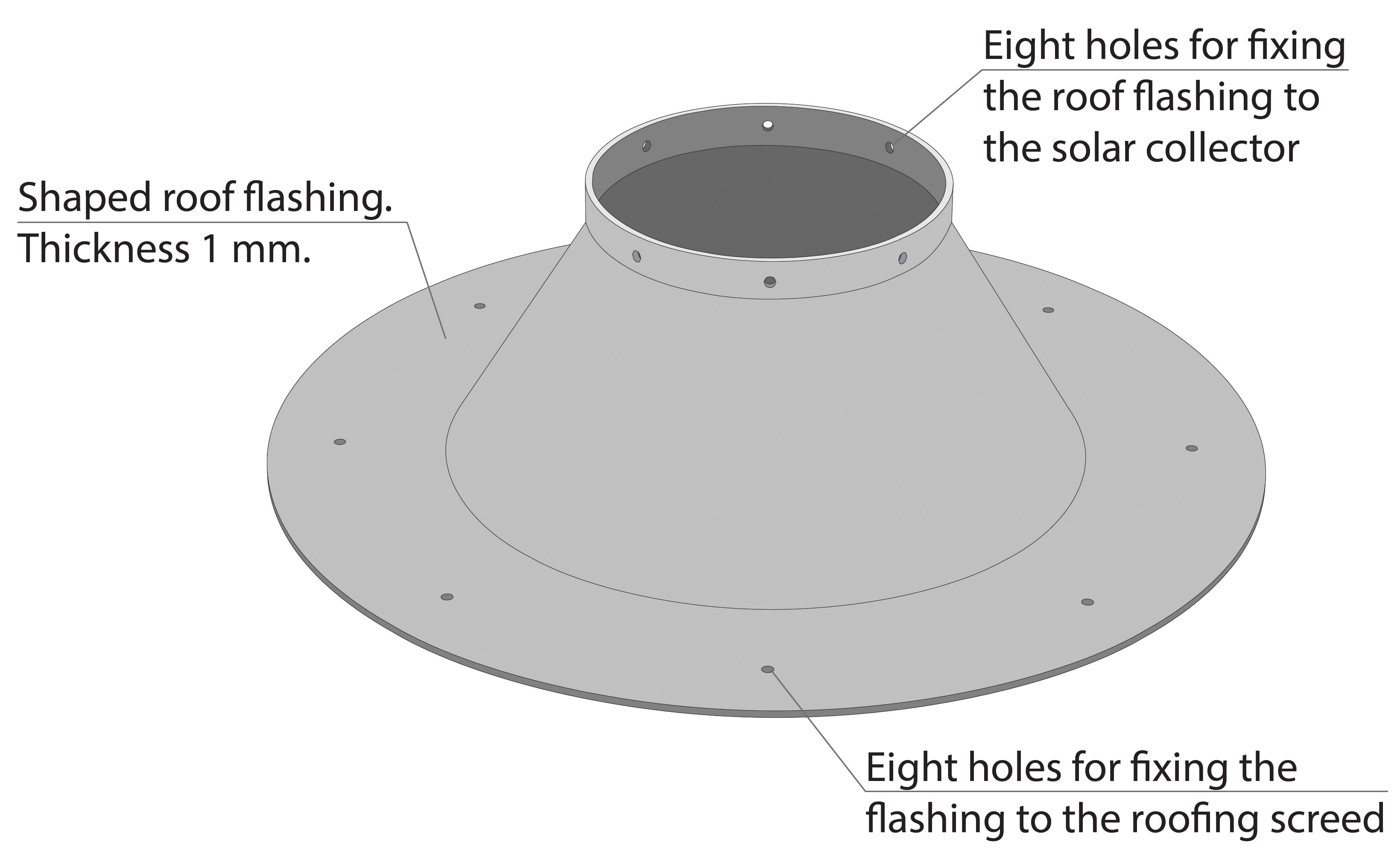
Fig. 3. Axonometric view of the flashing that allows anchor the system to the roof slab.
The upper part of the system consists of the elements shown in Fig. 4, which also displays how it can be fixed to the roof slab, inserting it into the flashing previously prepared. In Fig. 5(a) the connection of the system to the intermediate floor is shown, while Fig. 5(b) shows the telescopic shelf that is a fundamental element of the system. In addition, it allows setting the shelf at the correct height to facilitate the installation of the apparatus making the system extremely versatile and applicable at different heights.
Figure 4
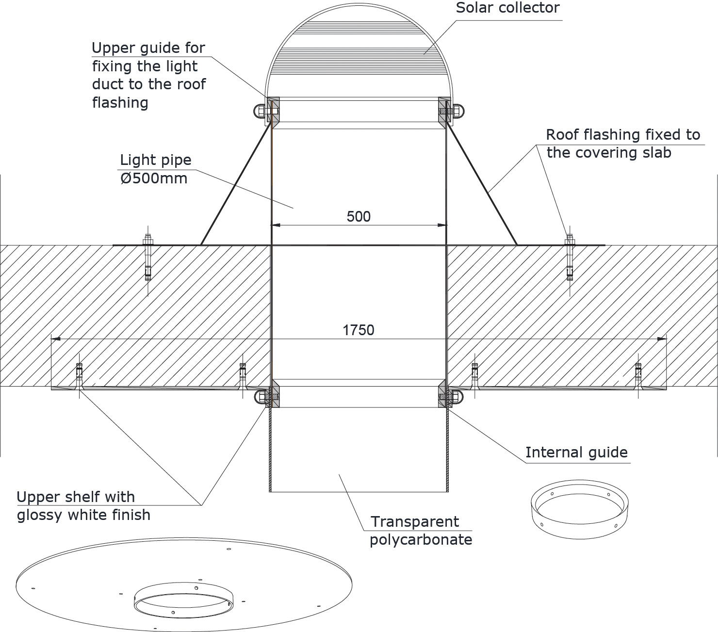
Fig. 4. Connection system to the roof slab.
Figure 5
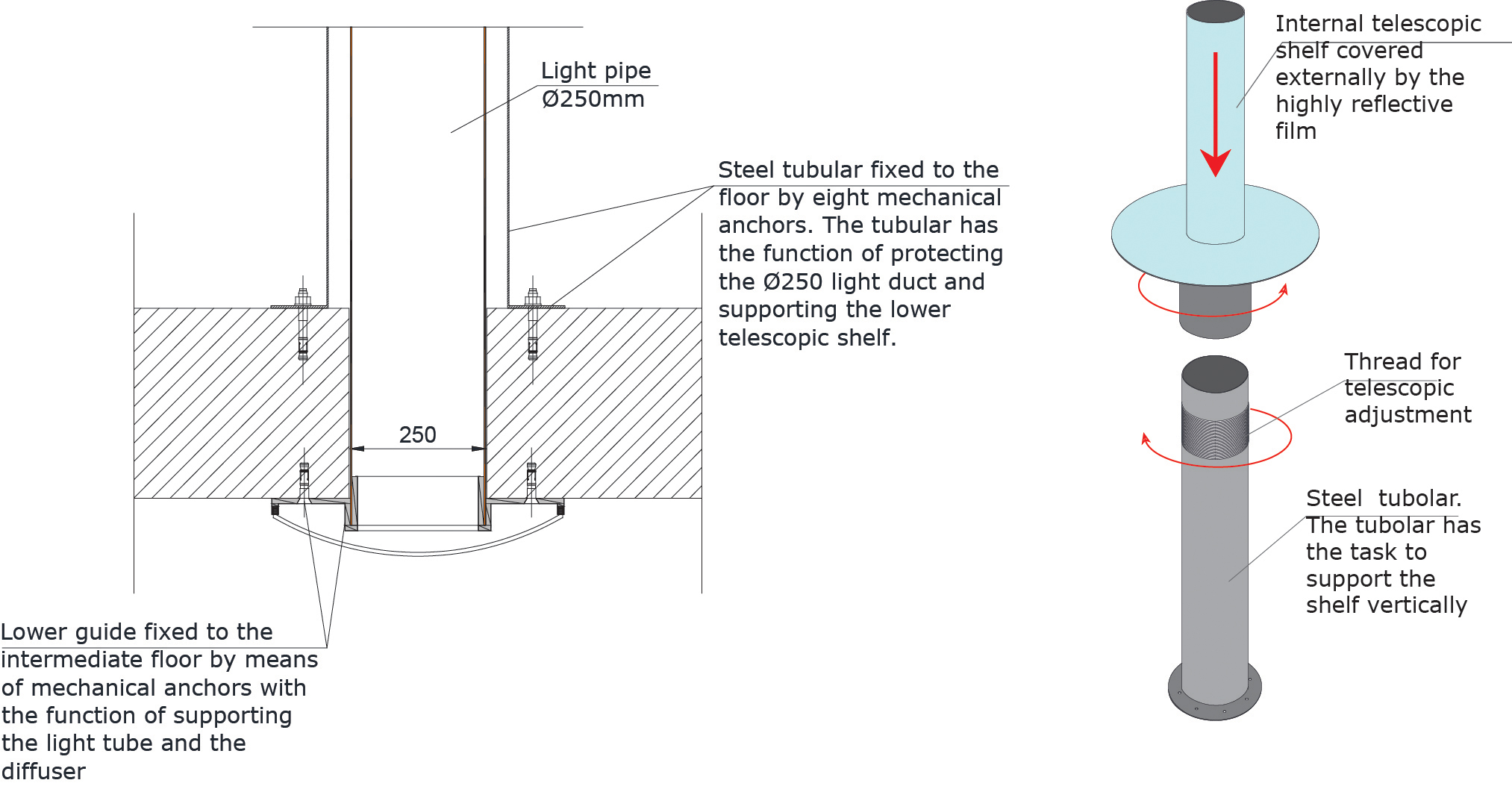
Fig. 5. (a) Fixing mode of the system to the inter-floor slab and (b) lower telescopic shelf.
Considering that the internal pipe is in contact with the users of the intermediate room, it is necessary to cover it with a steel coating, that protects it from any crashes with people or things. In addition, it supports the overlying telescopic element that can be used for changing the distance of the light shelf from the ceiling. Overall, the system looks like a long classic tube to which a steel circular protection has been applied to prevent damage. Finally, by assembling the components, the configuration shown in Fig. 6 is obtained.
Table 1 shows the luminous reflectance of the components of the MDLP.
Figure 6
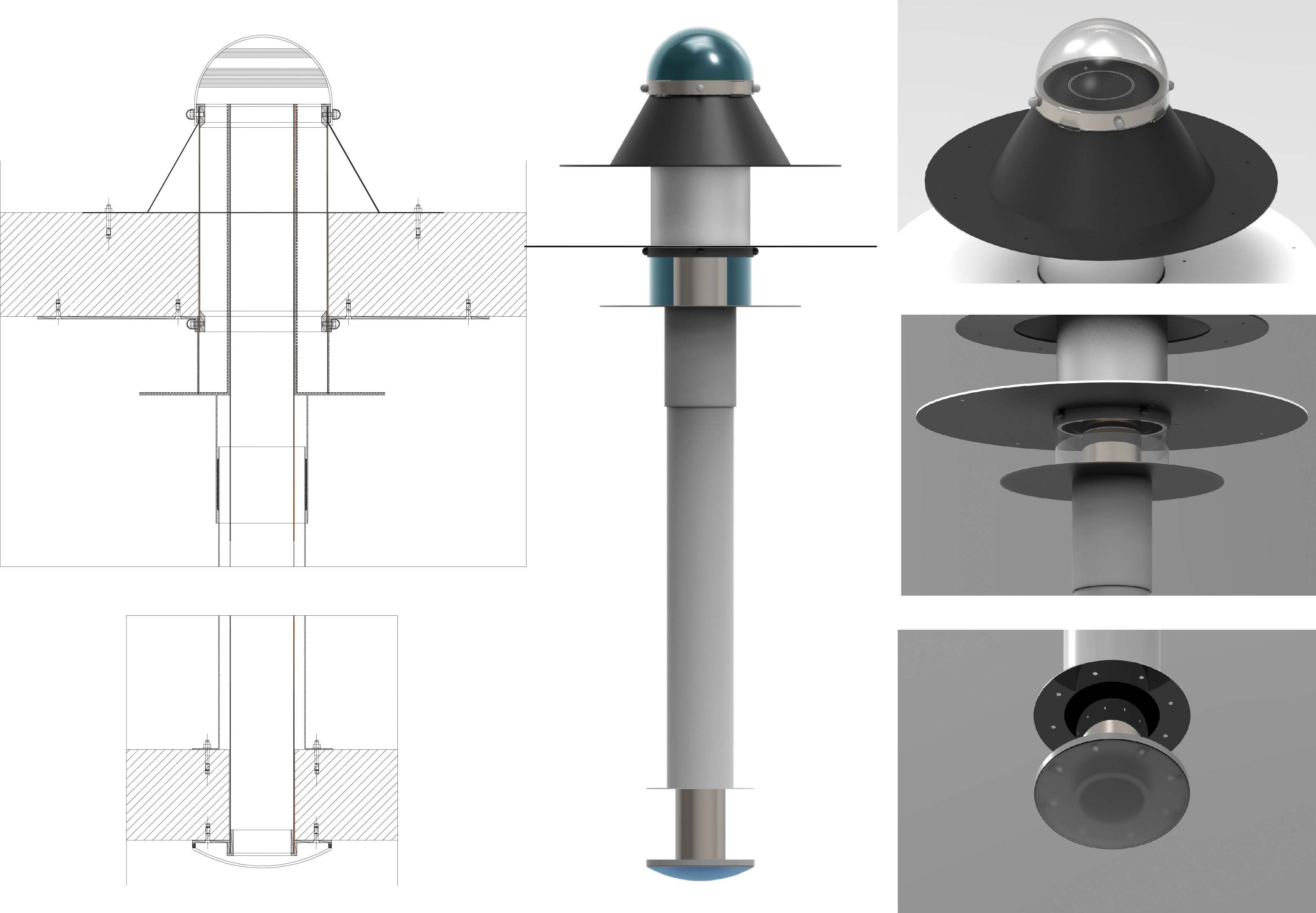
Fig. 6. Complete configuration of the MDLP, overall and detailed renderings.
Table 1
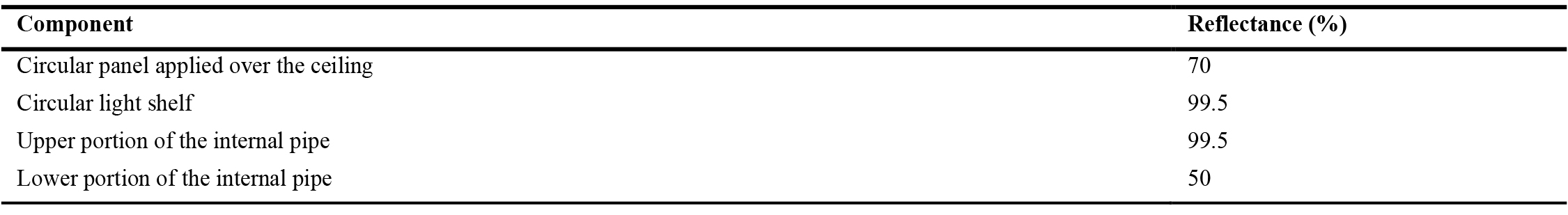
Table 1. Luminous reflectance of the components of the MDLP.
4. Description of the experimental apparatus
A wood 1:2 scale model of a 3.8×3.8 m plan area room, 3.0 m high was built by the authors. The vertical walls are made of unpainted multilayer wood, with a luminous reflectance equal to 50%. Sheets of grey drawing paper are applied to the floor of the room (luminous reflectance = 49.1%) and a circular grey panel (100 mm diameter) with the same luminous reflectance is applied over the ceiling around the external tube. The internal tube of the MDLP is made of PVC. The upper portion of it is externally covered by a reflective film (3 M Radiant Mirror Film LRF) with luminous reflectance r = 99.5%. The external tube is made of transparent polycarbonate. Figure 7 shows some photos of the device and the test room.
Figure 7
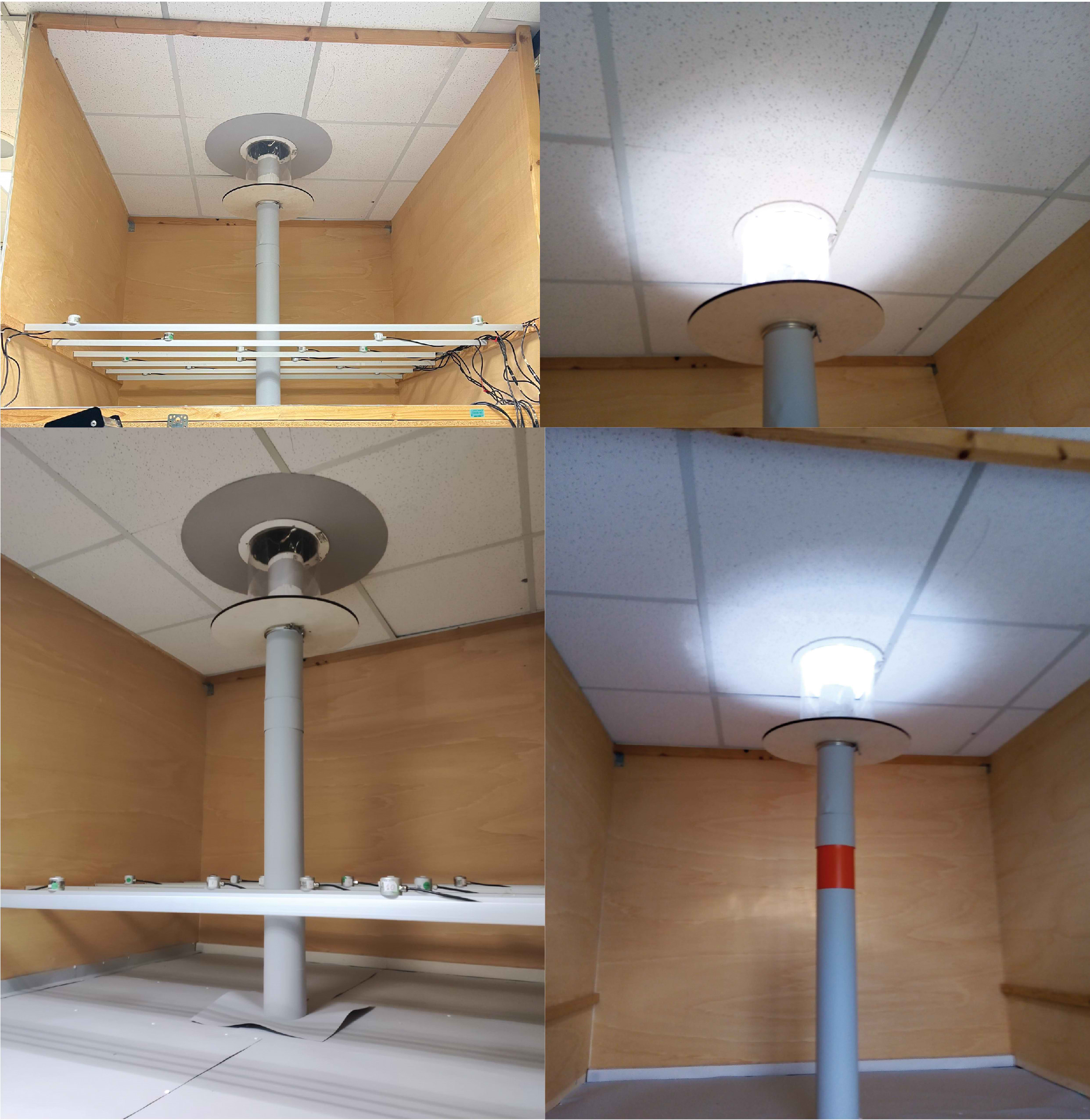
Fig. 7. Some photos of the MDLP and the test room.
The model simulates the passage room of a two-levels hypogeal construction illuminated by the MDLP. The room is not equipped with any windows or skylights, so the MDLP is the only source of natural light.
Twelve CIE Lux-meters sensors type LSI-BSR001, range 0–25 klx, accuracy 3% of the reading value for illuminance, have been positioned in the room on a horizontal work-plan (see Fig. 8). This last is 0.4 m high on the floor and simulates a 0.8 m high work-plan in the real scale room. A CIE sensor type LSI-DPA 503, range 0–100 klx, tolerance 1.5%, has been used to measure the external horizontal illuminance Eout. Figure 9 shows the external CIE sensor placed on the roof of the building during the experimental activity. Note that no obstructions take place from nearby buildings.
A data-logger type LSI Lastem ELO 310 has been used to register data.
Figure 8
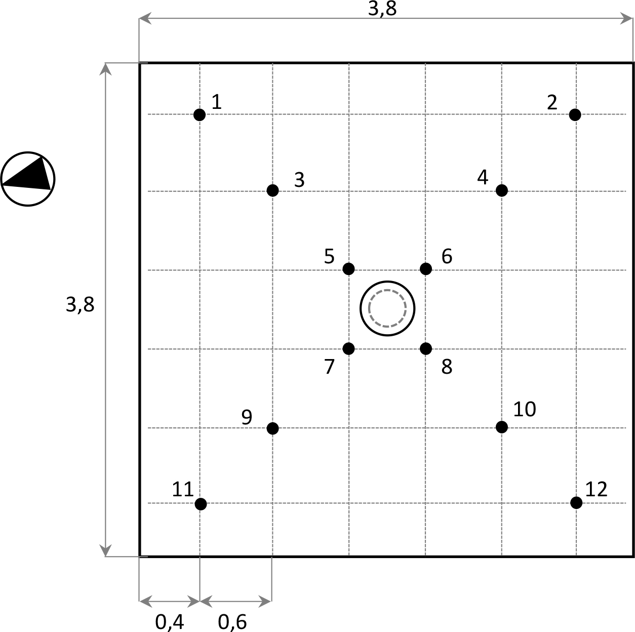
Fig. 8. Real scale dimensions of the test room and positions of the luxmeters on the horizontal work plane.
Figure 9
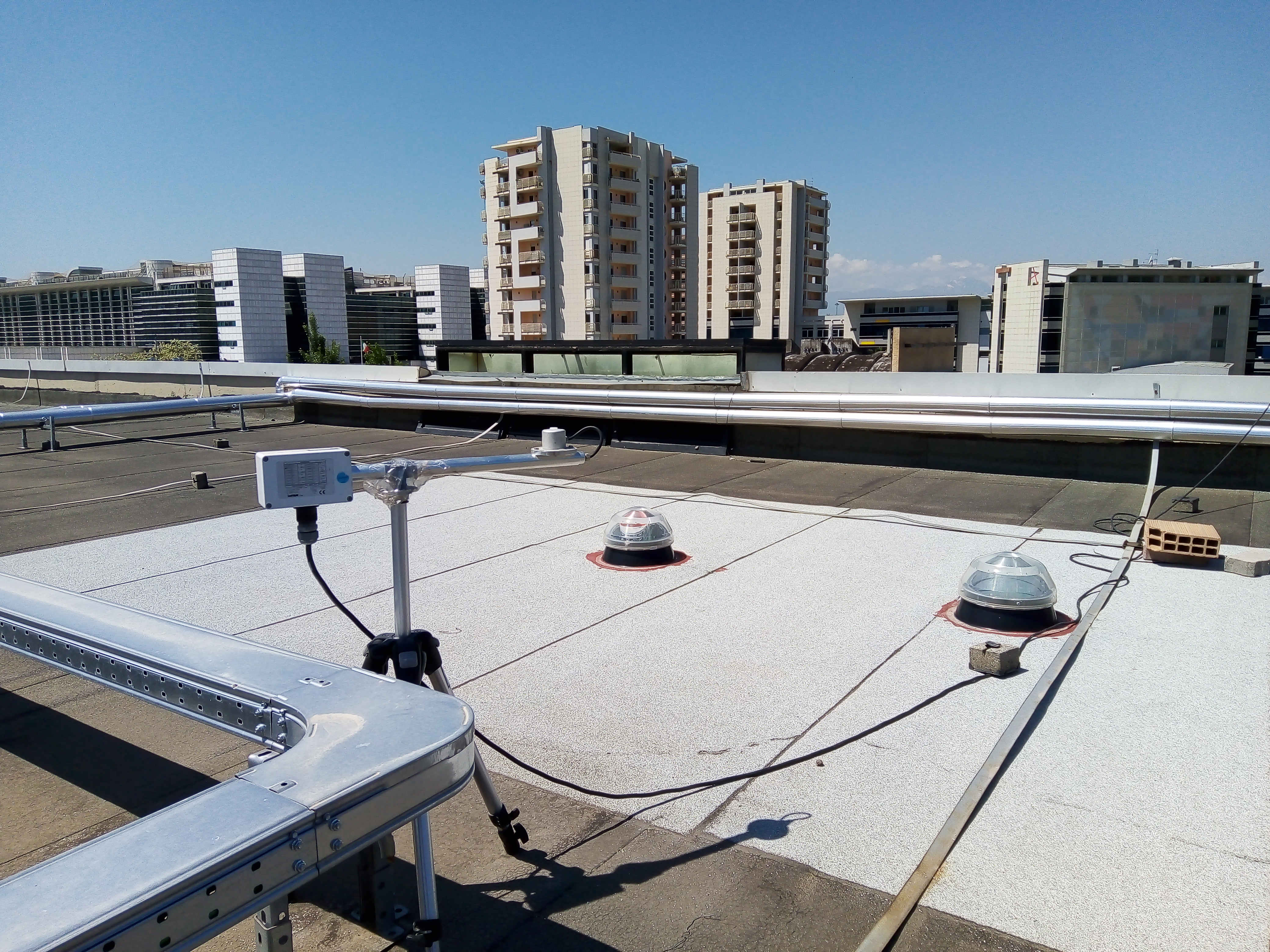
Fig. 9. The external luxmeter on the roof of the building.
5. Experimental results
The experimental activity was carried out from December the 22nd to January the 19th for 24 hours a day, collecting data of illuminance every one minute and elaborating them every ten minutes.
Figures 10 and 11 show the results of typical situations, respectively: a cloudy day (22 December), and a sunny day (5 January).
Figure 10
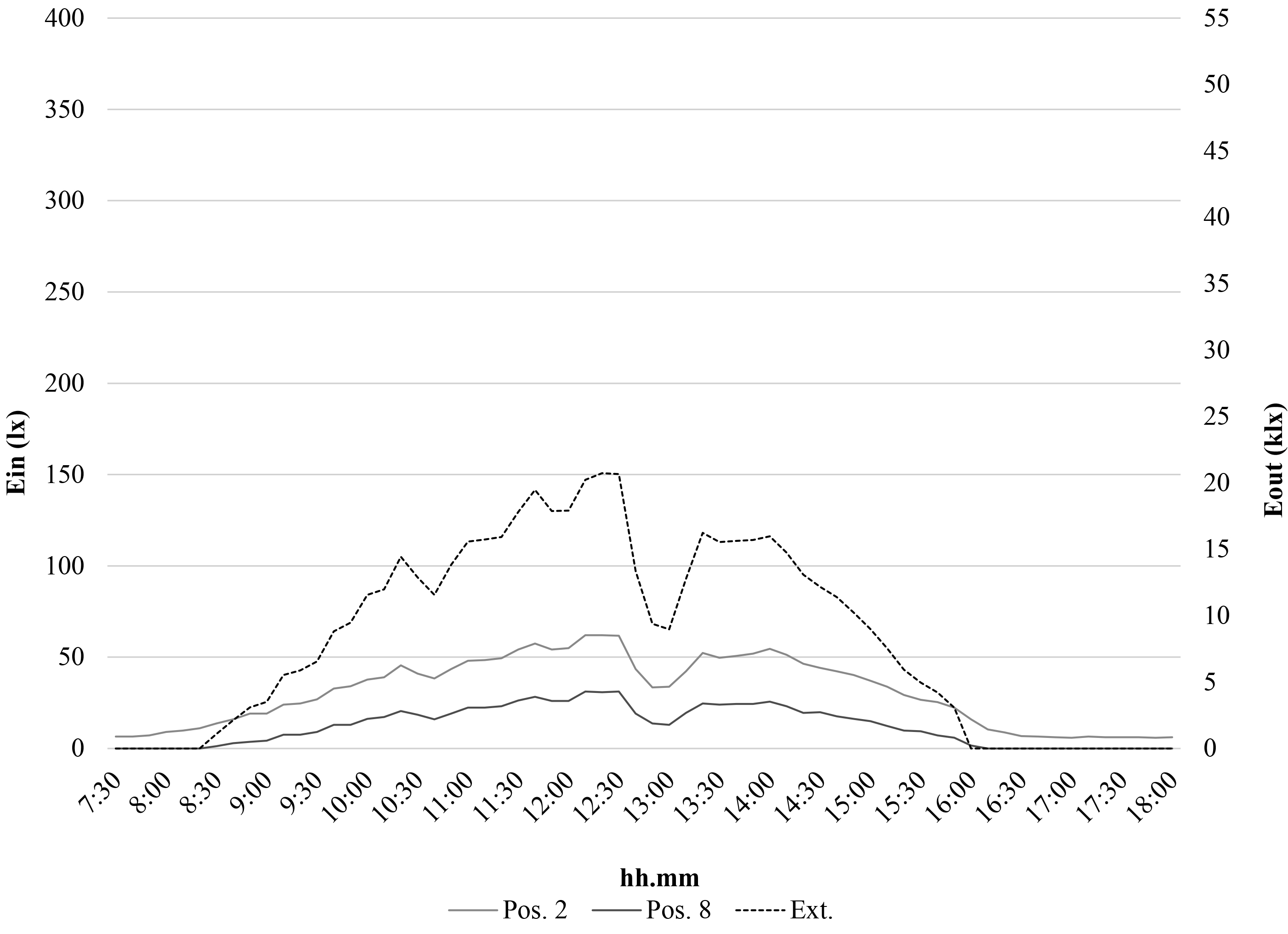
Fig. 10. Illuminance data of a typical overcast day (22 December). Data in positions other than 8 (minimum) and 2 (maximum) are overlapping between them - External illuminance referred to the right axis.
Figure 11
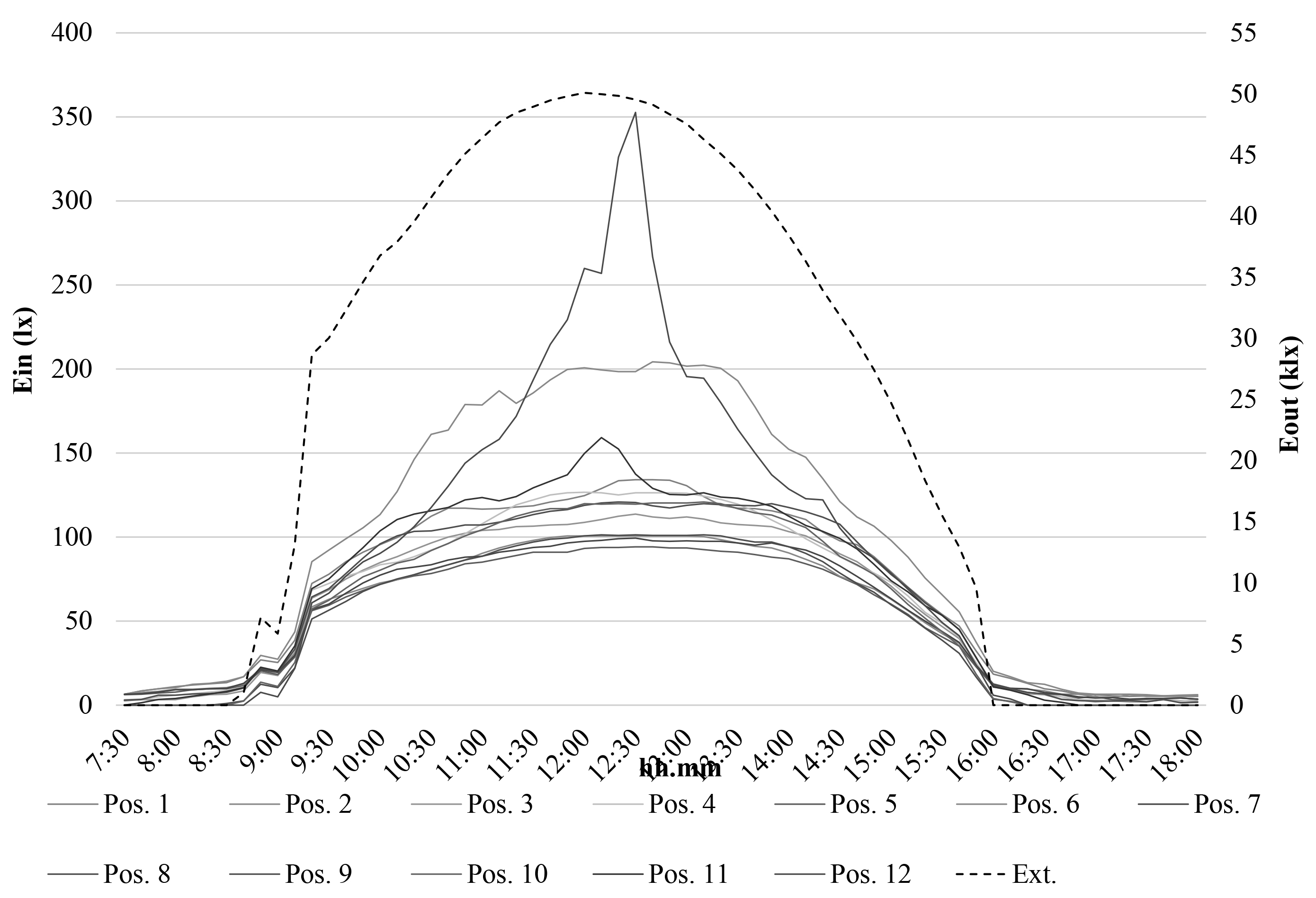
Fig. 11. Illuminance data of a typical overcast day (22 December). Data in positions other than 8 (minimum) and 2 (maximum) are overlapping between them - External illuminance referred to the right axis.
Under overcast sky (i.e., 22 December) the internal illuminance trend is very similar to the external one. The maximum external illuminance is about 21 klx and takes place at 12.30, while the internal illuminance is generally ranging between about 30 and 60 lx, except for the period from 12.30 to 13.30 during which it significantly decreases due to very low external illuminance values.
On the contrary, under clear sky with sun (i.e., 5 January) although the internal illuminance trend generally follows the external one, illuminance in positions 2 and 12 (in the right corners of the room) is significantly higher than in the other points. In particular, a peak value of about 350 lx takes place in position 12 at 12.30. Due to the low elevation of sun in winter conditions, in the central hours of the day, points 2 and 12 are hit by direct solar radiation without any interceptions by the light shelf. On January the 5th, the sun maximum elevation is ranging from 23.07° to 24.93° between 12.00 and 13.00, with azimuth equal to 162.82° - 177.83 °.
This does not occur with overcast sky, such as on December the 22nd, due to quite a complete absence of direct solar radiation.
Note that in Fig. 9 data in positions other than 8 (minimum) and 2 (maximum) have not been shown because they are overlapping and included between them.
Moreover, note that while on December the 22nd the external and internal maximum values of illuminance are perfectly simultaneous, on January the 5th there is a time shift of 30 minutes between them.
Moving from the previous considerations, the authors analyzed data of all the test days to determine the correlation between internal and external illuminance.
Table 2 shows the internal and external average and maximum illuminance values for each day between sunrise and sunset, the measure positions in which the maximum value happens, and the time shift between internal and external maximum values.
Table 2
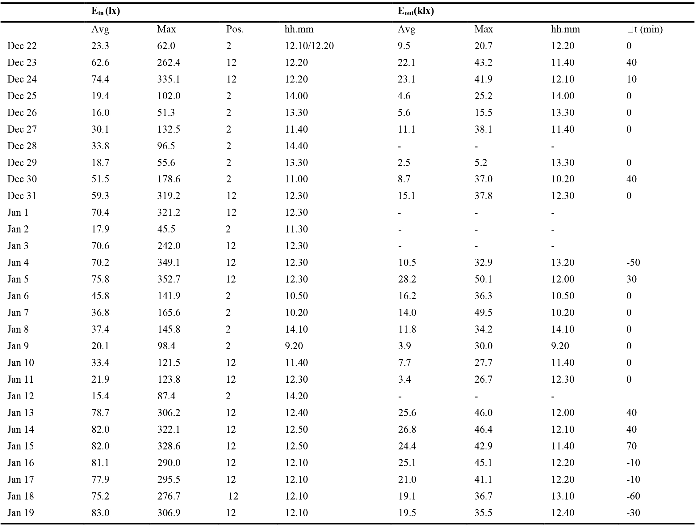
Table 2. Average and maximum illuminance values, measure positions of maximum values and time shift between internal and external maximum illuminances.
Note that the table is lacking external illuminance data for five days (28 December, 1-3 January, 12 January) due to an accidental breakdown of the external luxmeter.
Maximum values take always place in positions 2 (13 times) and 12 (16 times), on the right side of the room.
For twelve days, the internal and external values are simultaneous, while for eleven days, there is a time shift between them, six times late and five times early. The maximum delay occurs on January the 15th (70 min), while the maximum advance occurs on January the 18th (60 min). The contemporaneity generally happens with low external illuminance on partially or fully cloudy days, while the time shift generally takes place on sunny days under clear sky with sun.
The reason for these time lags is not easily determined. They are probably due to many causes. First, both the internal and external illuminances are not instantaneous values but average values every ten minutes. Secondly, in addition to direct radiation, diffuse radiation and multiple reflections from some parts of the system and the walls contribute to determining the illuminance in an internal point. Finally, the external illuminance sometimes is maximum when the position of the sun on the sky is not such as to directly interface the most illuminated points (i.e., 2 and 12). In these cases, direct solar radiation does not hit any sensor and it is not registered.
5.1. Illuminance uniformity
The authors considered the parameter “Illuminance Uniformity”. According to the EN12464-1, it can be defined in two different ways, as shown respectively in Eqs. (1) and (2):
Table 3 and Figs. 12 and 13 show the calculated values of U0 and U0' for all the test days at 10.00, 12.30 and 15.30.
Table 3
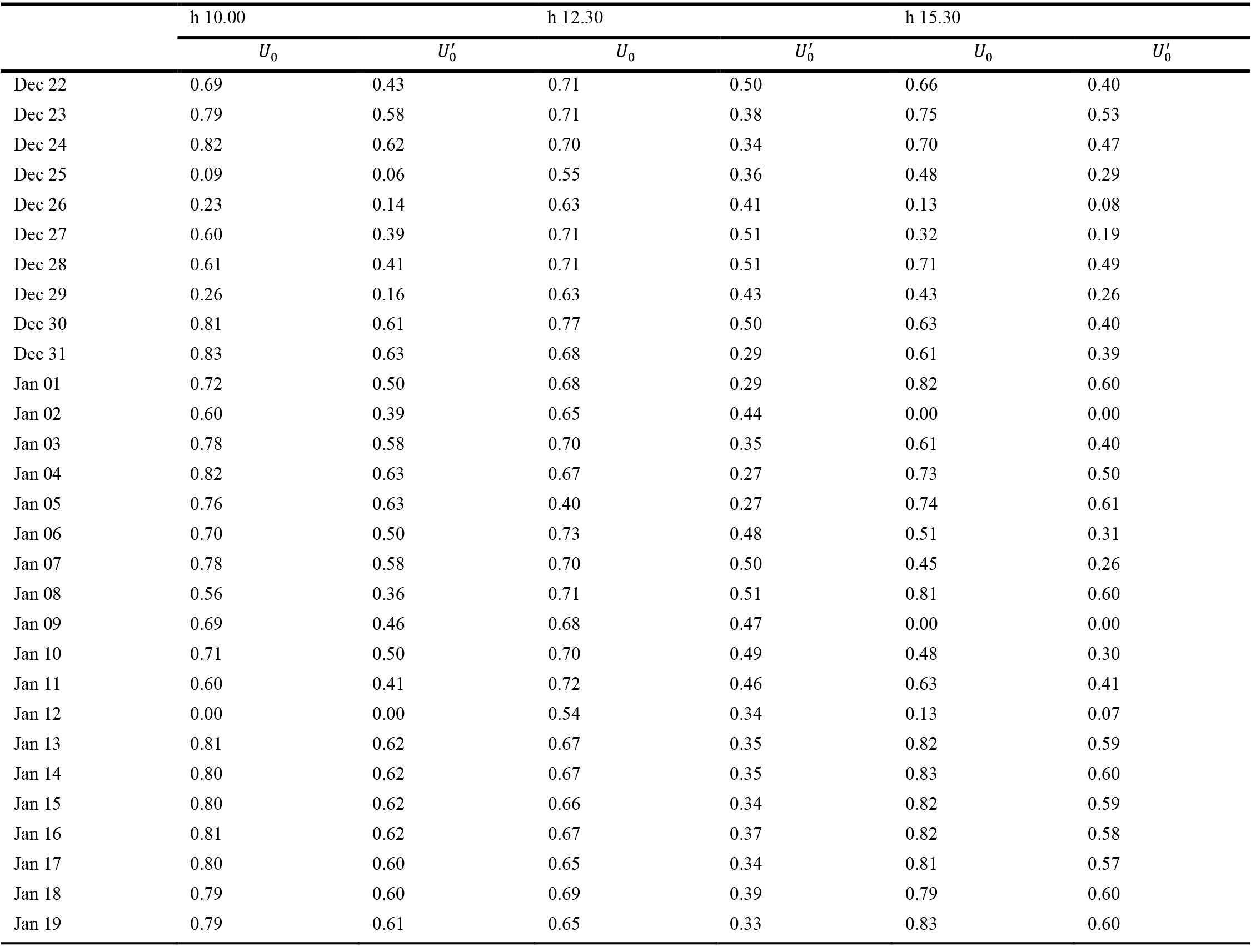
Table 3. Calculated values of Illuminance uniformity.
Figure 12
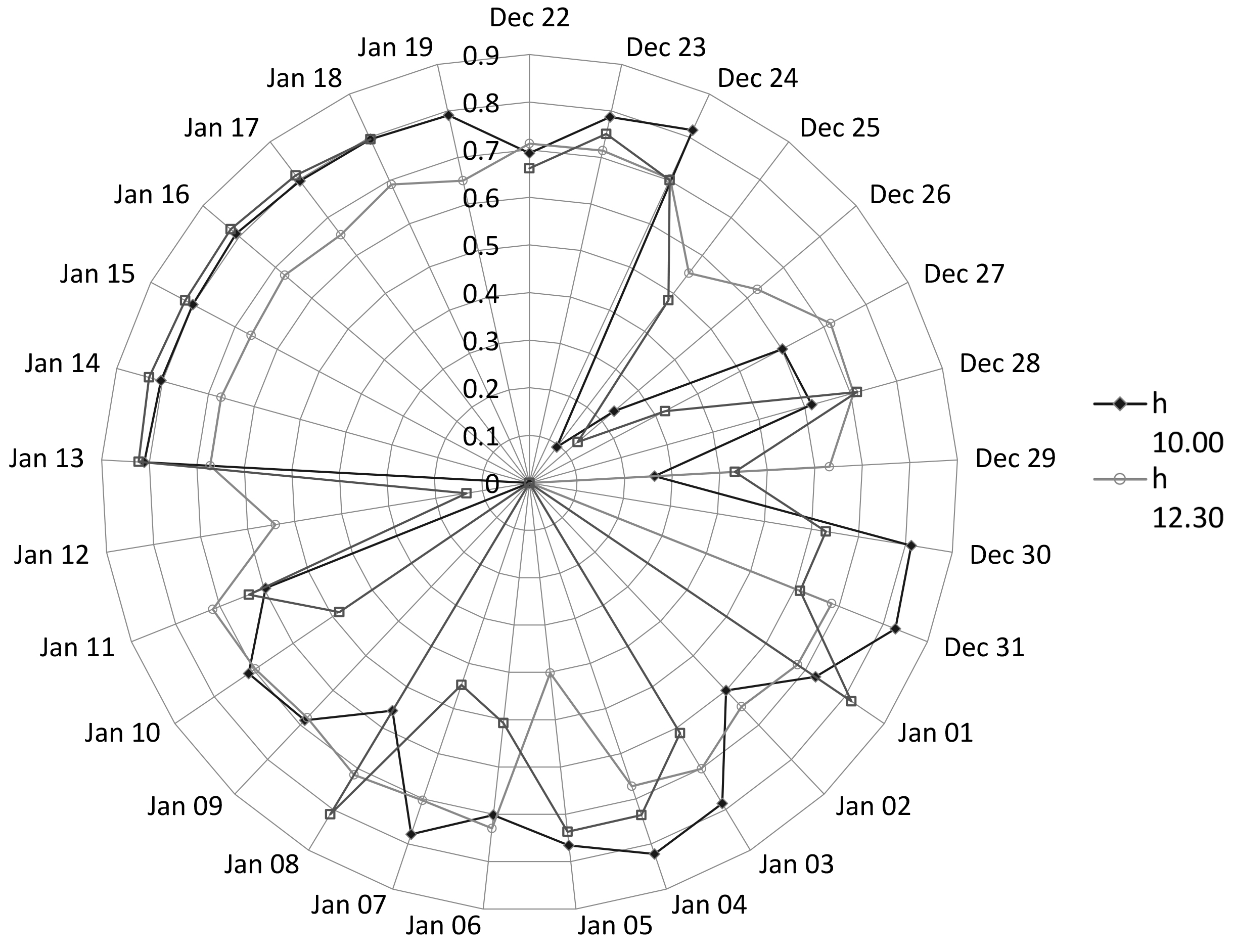
Fig. 12. Illuminance uniformity, U0, on the work plane for all the test days at 10.00, 12.30, and 15.30.
Figure 13
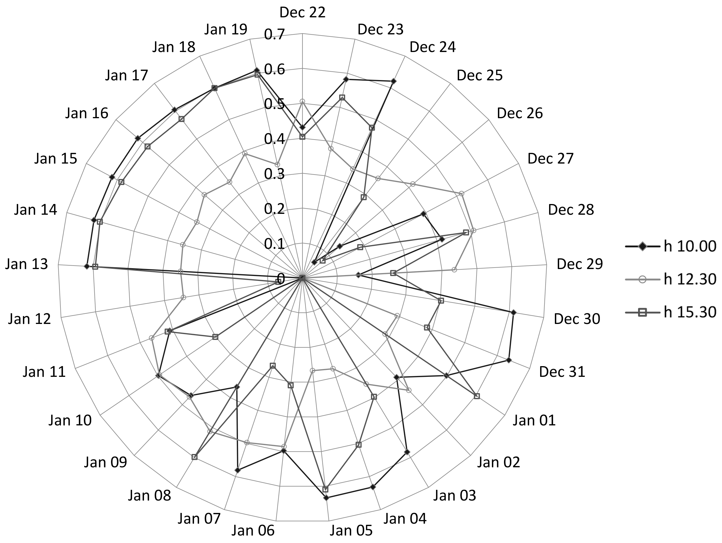
Fig. 13. Illuminance uniformity, Uo', prime on the work plane for all the test days at 10.00, 12.30, and 15.30.
From data reported in Table 3 and Figs. 12 and 13, we can deduce that the illuminance uniformity is not ideal because U0' is higher than 0.5 only in 38 % of cases, it is never higher than 0.8 and it is lower than 0.4 in 39 % of cases. Furthermore, U0 is higher than 0.8 only in 18 % of cases and lower than 0.5 in 16 % of cases, while in 66 % of cases it ranges between 0.5 and 0.8 (31 % between 0.7 and 0.8 - 29 % between 0.6 and 0.7 - 5 % between 0.5 and 0.6).
On the other hand, some authors underline that these criteria seem to be too restrictive for environments illuminated with natural light where a lower degree of uniformity is tolerated by users if compared to similar situations but with the use of artificial light [44].
Table 3 and Figs. 12 and 13 show that U0 and U0' have similar values for some days (i.e., 13-19 Jan). This trend is typical of sunny days with high external illuminance. In these cases, the illuminance uniformity is very similar at 10.00 and 15.30 and it is significantly lower at 12.30, probably due to the high value of solar elevation that causes less spatial penetrating reflections of solar radiation.
Figure 14 shows the results on January the 16th as an example of a sunny day. Sensors in positions 2 and 12 have the maximum values all the time with high illuminance between 12.00 and 13.00, respectively 287 lx in position 12 at 12.20, and 242 lx in position 2 at 13.00. In the other measure positions, illuminance ranges between 100 and 160 lx. It is noteworthy that the maximum values of illuminance take place further away from the system, so improving the light uniformity on the work-plan.
Figure 14
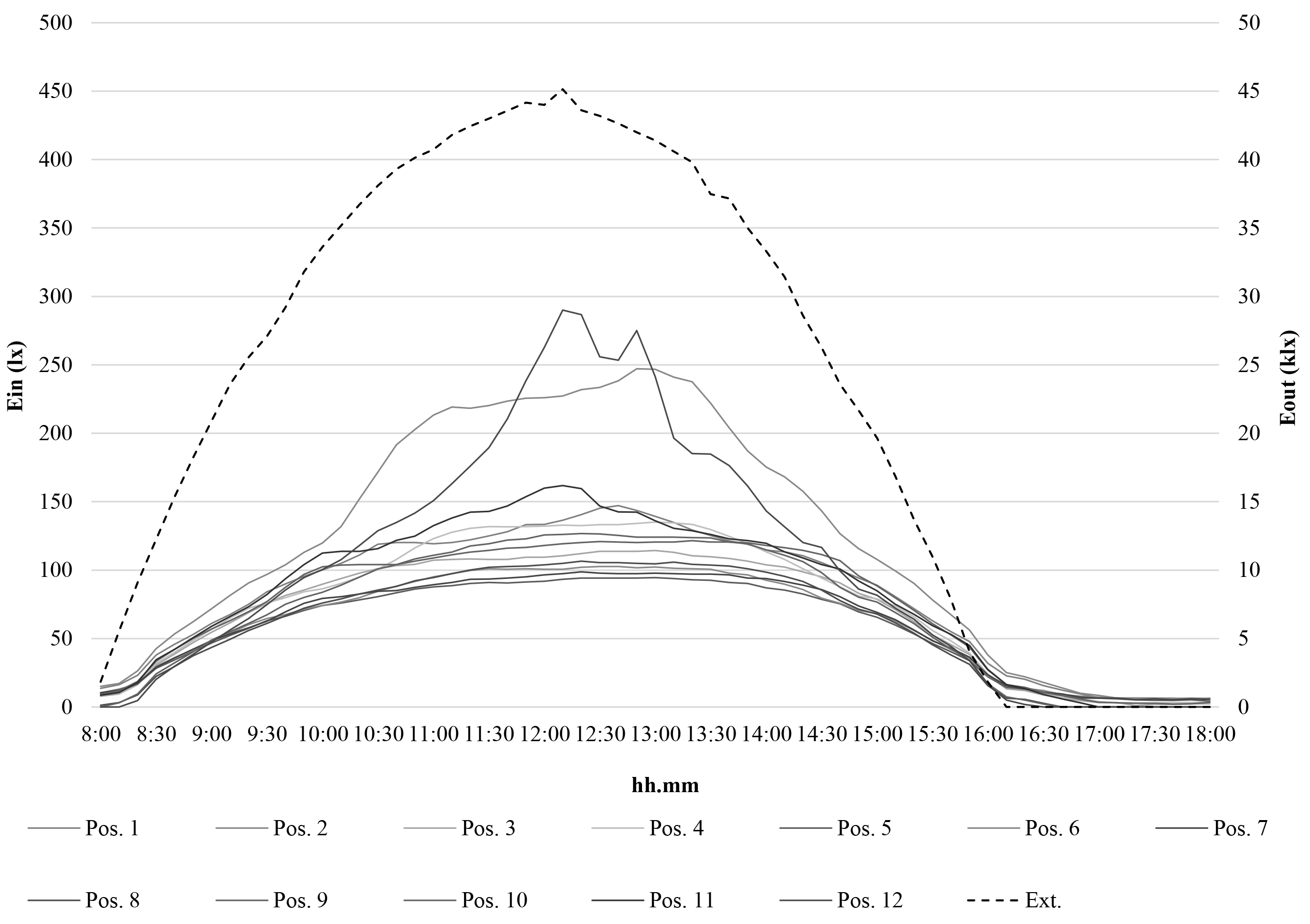
Fig. 14. Illuminance data on January the 16th - External illuminance referred to the right axis.
When direct solar radiation is quite absent and external illuminance is low, such as during cloudy days, the internal illuminance trend is very similar to the external one, without peak values. Figures 15 and 16 show the results on December 25 and 26 as an example of this situation.
Figure 15
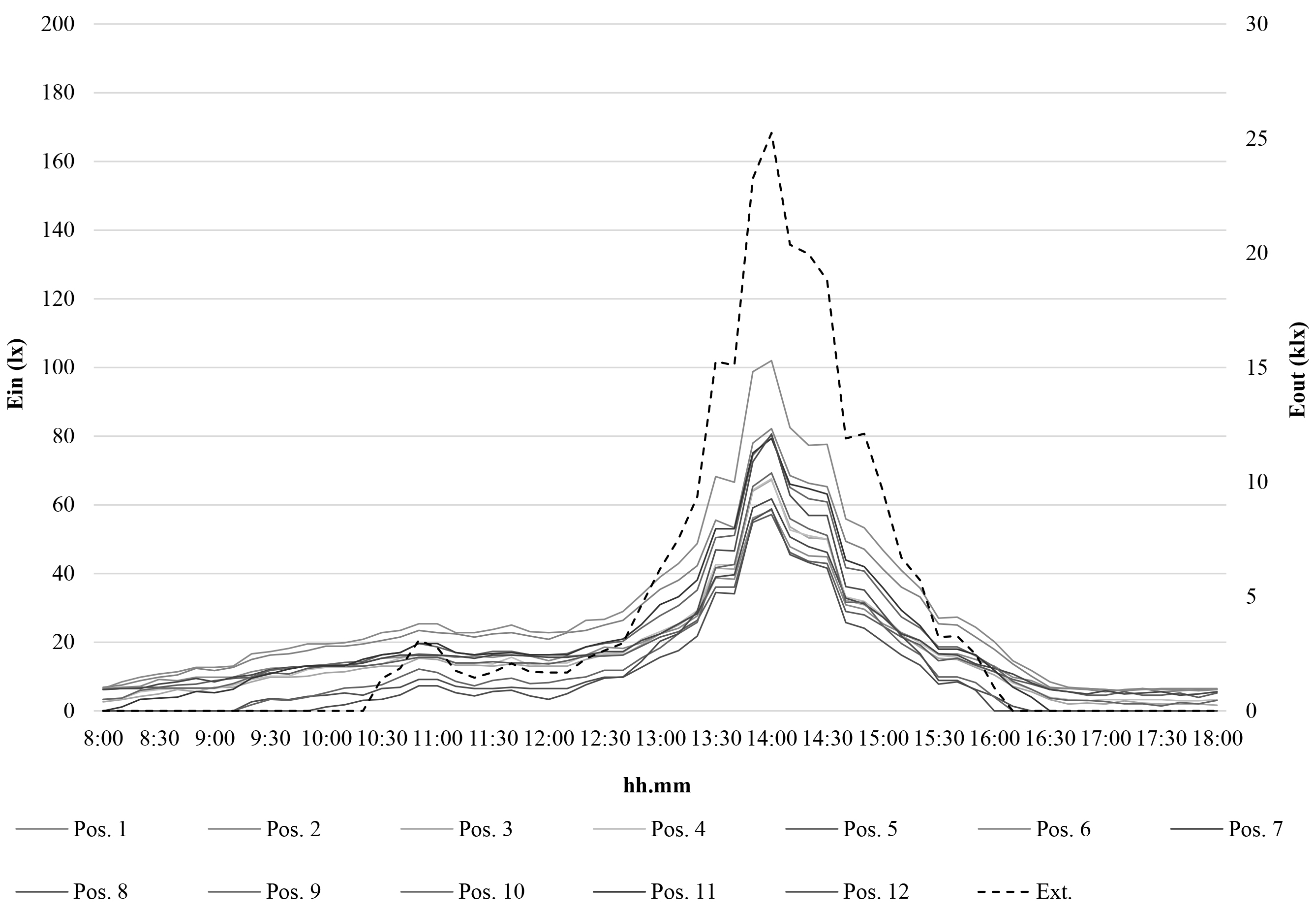
Fig. 15. Illuminance data on December the 25th - External illuminance referred to the right axis.
Figure 16
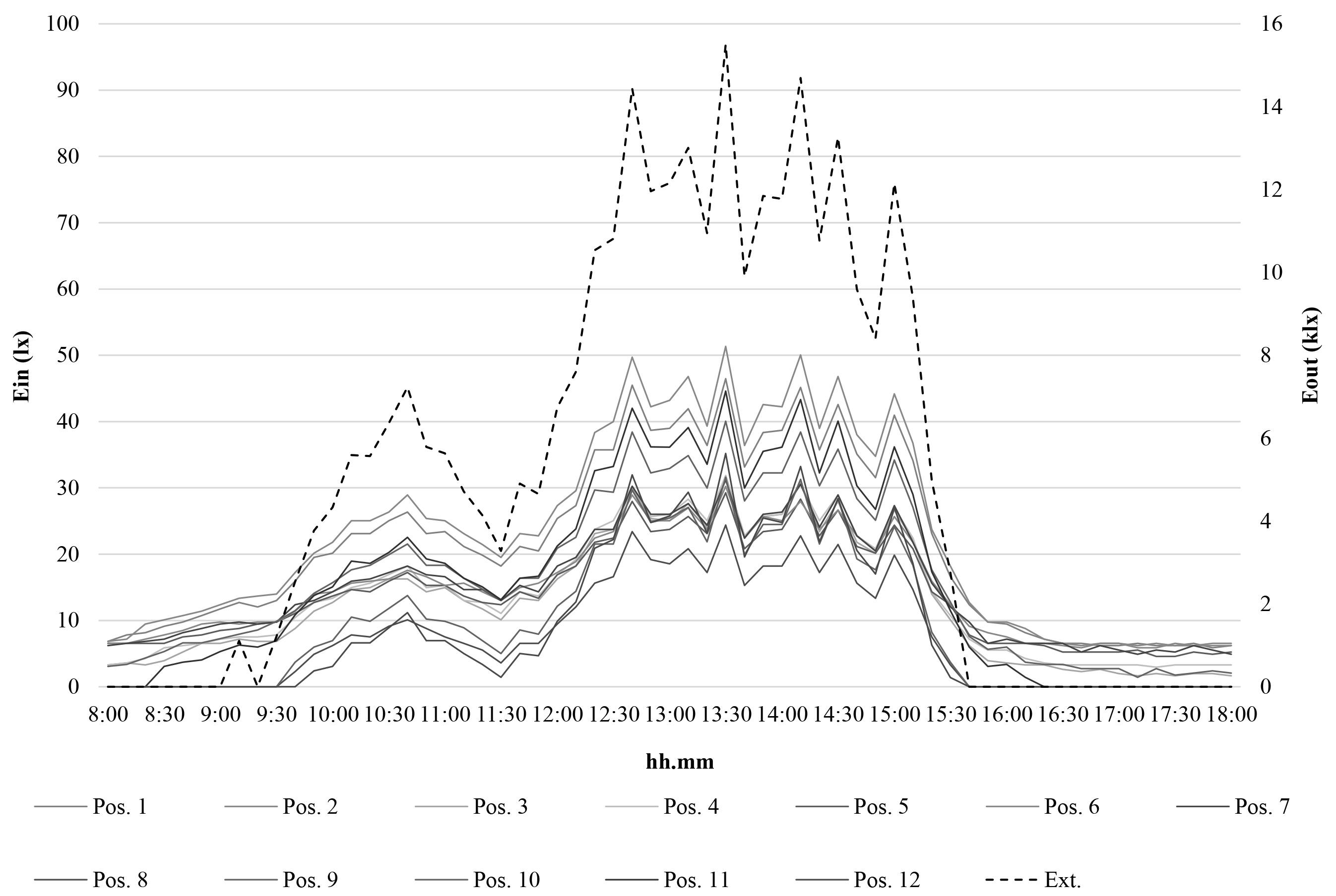
Fig. 16. Illuminance data on December the 26th - External illuminance referred to the right axis.
Note that also in these cases, the maximum values of internal illuminance take place in the corners of the room (position 1, 2, 11 or 12) as evidence of the fact that even in the absence of intense direct solar radiation, the light shelf effectively contributes to the diffusion of light in the environment.
6. Conclusions
This paper describes the results of a preliminary experimental activity carried out on a reduced scale model of the MDLP, an innovative daylighting system, set up by modifying the DLP previously developed by the authors.
The experimental activity has been carried out in winter climatic conditions, between December 2021 and January 2022. The first results seem to be appreciable and encourage further investigation to better define the performance of the device.
Some problems of the DLP have been attenuated: the cut of the lower part of the external tube decreases the overall dimensions of the system and the application of a light shelf on its upper portion reduces the risk of glare and improves the illuminance uniformity on the horizontal work-plan.
Although the tests were carried out in winter conditions, with low external illuminance, the system contributes to light distribution in the passage room of underground buildings. On sunny days, with maximum external illuminance of about 45 klx, internal illuminance is around 100 - 150 lx most of the time between sunrise and sunset. Peak values of illuminance have been registered in positions close to the right side of the room, caused by intense direct solar radiation not intercepted by the light shelf, due to the low elevation angle of the sun. Taking into account that the tests have been carried out in winter climatic conditions, illuminance data on the work-plan can be considered satisfactory for underground environments.
The illuminance uniformity is not completely satisfactory, but it can be judged acceptable considering that a lower degree of uniformity is tolerated by users of environments illuminated with natural light instead of artificial light.
Finally, the technological components of the system have been described in detail, as well as the installation procedure for a generic brick concrete roof slab.
The authors intend to continue the experimental activity on the scale model of the MDLP to collect a sufficient amount of data available to define the principal daylight dynamic parameters, as the Spatial Daylight Autonomy or the Useful Daylight Illuminance. In addition, they are going to carry out a parametric analysis of the performance of the MDLP through a numerical activity.
Contributions
All the authors contributed equally.
Declaration of competing interest
The authors declare no conflict of interest.
References
- C. Baroncini, O. Boccia, F. Chella, P. Zazzini, Experimental analysis on a 1:2 scale model of the double light pipe, an innovative technological device for daylight transmission, Solar Energy 84 2 (2010) 296-307. https://doi.org/10.1016/j.solener.2009.11.011
- A. Tabadkani, A. Roetzel, H. Xian Li, A. Tsangrassoulis, Daylight in Buildings and Visual Comfort Evaluation: the Advantages and Limitations, Journal of Daylighting 8 (2021) 181-203. https://doi.org/10.15627/jd.2021.16
- J. H. Heerwagen, D. R. Heerwagen, Lighting and psychological comfort, Lighting Design and Application 16 4 (1986) 47-51.
- Z. Hamedani, E. Solgi, H. Skates, T. Hine, R. Fernando, J. Lyons, K. Dupre, Visual discomfort and glare assessment in office environments: a review of light-induced physiological and perceptual responses, Building and Environment 153 (2019) 267-280. https://doi.org/10.1016/j.buildenv.2019.02.035
- A. D. Galasiu, J. A. Veitch, Occupant preferences and satisfaction with the luminous environment and control systems in daylit offices: a literature review, Energy and Buildings 38 (2006) 728-742. https://doi.org/10.1016/j.enbuild.2006.03.001
- M. De Carli, V. De Giuli, R. Zecchin, Review on visual comfort in office buildings and influence of daylight in productivity, in: Indoor Air, 2008, pp. 17-22, Copenhagen, Denmark.
- E. C. Yilmaz, R. Abdulhaq, Assessment of the circadian stimu¬lus potential of an integrative lighting system in an office area, MSc thesis (2020), Faculty of Engineering, Lund University, Sweden.
- R. Campama Pizarro, N. Gentile, A case study addressing the benefits of integrated solutions for daylighting and electric lighting in the retail sector, in: ISES Solar World Congress, 2019, pp. 1825-1836, Santiago, Chile. https://doi.org/10.18086/swc.2019.38.02
- M. Boubekri, R. Hull, L. Boyer, Impact of window size and sunlight penetration on office workers' mood and satisfaction: A novel way of assessing sunlight, Environment and Behaviour 23 4 (1991) 474-493. https://doi.org/10.1177/0013916591234004
- P. Leather, M. Pyrgas, D. C. Beale. C. Lawrence, Windows in the workplace: sunlight, view, and occupational stress, Environment and Behaviour 30 (1998) 739-762. https://doi.org/10.1177/001391659803000601
- L. Bellia, F. Fragliasso, A. Pedace, Evaluation of daylight availability for energy savings, Journal of Daylighting 2 (2015) 12-20. https://doi.org/10.15627/jd.2015.2
- M. Bodart, A. De Herde, G. Lobal, Energy savings in offices buildings by the use of daylighting, Energy and Buildings 34 (2002) 421-429. https://doi.org/10.1016/S0378-7788(01)00117-7
- E. J. Gago, T. Muneer, M. Knez, H. Köster, Natural light controls and guides in buildings. Energy saving for electrical lighting, reduction of cooling load, Renewable and Sustainable Energy Reviews 41 (2015) 1-13. https://doi.org/10.1016/j.rser.2014.08.002
- J. Mardaljevic, L. L. Heschong, E. S. Lee, Daylight metrics and energy savings, Lighting Research and Technology 41 (2009) 261-283. https://doi.org/10.1177/1477153509339703
- A. M. Momani, B. Yatim, M. Alauddin, M. Ali, The impact of the daylight saving time on electricity consumption a case study from Jordan, Energy Policy 37 (2009) 2042-2051. https://doi.org/10.1016/j.enpol.2009.02.009
- I. Pyonchan, N. Abderrezek, K. Moncef, Estimation of lighting energy savings from daylighting, Building and Environment 44 (2009) 509-514. https://doi.org/10.1016/j.buildenv.2008.04.016
- B. Obradovic, B. S. Matusiak, Daylight Transport Systems for Buildings at High Latitudes, Journal of Daylighting 6 2 (2019) 60-79. https://doi.org/10.15627/jd.2019.8
- B. Obradovic, B. S. Matusiak, Daylight autonomy improvement in buildings at high latitudes using horizontal light pipes and light-deflecting panels, Solar Energy 208 (2020) 493-514. https://doi.org/10.1016/j.solener.2020.07.074
- O. T. Masoso, L. J. Grobler, The dark side of occupants' behaviour on building energy use, Energy and Buildings 42 (2010) 173-177. https://doi.org/10.1016/j.enbuild.2009.08.009
- S. Carlucci, F. Causone, F. De Rosa, L. Pagliano, A review of indices for assessing visual comfort with a view to their use in optimization processes to support building integrated design, Renewable and Sustainable Energy Reviews 47 (2015) 1016-1033. https://doi.org/10.1016/j.rser.2015.03.062
- R. Canziani, F. Peron, G. Rossi, Daylight and energy performances of a new type of light pipe, Energy and Buildings 36 11 (2004) 1163-1176. https://doi.org/10.1016/j.enbuild.2004.05.001
- D. Jenkins, T. Muneer, J. Kubie, A design tool for predicting the performances of light pipes, Energy and Buildings 37 5 (2005) 485-492. https://doi.org/10.1016/j.enbuild.2004.09.014
- H. von Wachenfelt, V. Vakouli, A. P Diéguez, N. Gentile, M. C. Dubois, K. H. Jeppsson, Lighting Energy Saving with Light Pipe in Farm Animal Production, Journal of Daylighting 2 2 (2015) 21-31. https://doi.org/10.15627/jd.2015.5
- A. A. Freewan, L. Shao, S. Riffat, Optimizing performance of the light shelf by modifying ceiling geometry in highly luminous climates, Solar Energy 82 (2008) 343-353. https://doi.org/10.1016/j.solener.2007.08.003
- A. Ganga, B. R. Warrier, Performance evaluation of light shelves, Energy and Buildings 140 (2017) 19-27. https://doi.org/10.1016/j.enbuild.2017.01.068
- A. Kontadakis, A. Tsangrassoulis, L. Doulos, S. Zerefos, A Review of Light Shelf Designs for Daylit Environments, Sustainability 10 1 (2018) 71-94. https://doi.org/10.3390/su10010071
- A. Meresi, Evaluating daylight performance of light shelves combined with external blinds in south-facing classrooms in Athens, Greece, Energy and Buildings 116 (2016) 190-205. https://doi.org/10.1016/j.enbuild.2016.01.009
- G. A. Warrier, B. Raphael, Performance evaluation of light shelves, Energy and Buildings 140 (2017) 19-27. https://doi.org/10.1016/j.enbuild.2017.01.068
- Y. W. Lim, M. H. Ahmad, The effects of direct sunlight on light shelf performance under tropical sky, Indoor and Built Environment 24 6 (2015) 788-8022. https://doi.org/10.1177/1420326X14536066
- P. Zazzini, A. Romano, A. Di Lorenzo, V. Portaluri, A. Di Crescenzo, Experimental Analysis of the Performance of Light Shelves in Different Geometrical Configurations through the Scale Model Approach, Journal of Daylighting 7 (2020) 37-56. https://doi.org/10.15627/jd.2020.4
- S. Ahmed, A. Zain-Ahmed, S. A. Rahman, M. H. Sharif, Predictive tools for evaluating daylighting performance of light pipes, International Journal of Low-Carbon Technologies 1 (2006) 315-328. https://doi.org/10.1093/ijlct/1.4.315
- D. J. Carter, The measured and predicted performance of passive solar light pipe systems, Lighting Research and Technology 34 1 (2002) 39-51. https://doi.org/10.1191/1365782802li029oa
- S. Dutton. L. Shao, Raytracing simulation for predicting light pipe transmittance, International Journal of Low-Carbon Technologies 2 4 (2007) 339-358. https://doi.org/10.1093/ijlct/2.4.339
- D. H.W. Li, E. K.W. Tsang, C. C. O. Tam, An analysis of light-pipe system via full-scale measurements, Applied Energy 87 3 (2010) 799-805. https://doi.org/10.1016/j.apenergy.2009.09.008
- G. Oakley, S. B. Riffat, L. Shao, Daylight performance of light pipes, Solar Energy (2000) 69 2 89-98. https://doi.org/10.1016/S0038-092X(00)00049-9
- M. Paroncini, B. Calcagni, F. Corvaro, Monitoring of a light-pipe system. Solar Energy 81 9 (2007) 1180-1186. https://doi.org/10.1016/j.solener.2007.02.003
- A. Rosemann, H. Kaase, Light pipe applications for daylighting systems Solar Energy 78 (2005) 772-780. https://doi.org/10.1016/j.solener.2004.09.002
- Y. Su, N. Khan, S. B. Riffat, O. Gareth, Comparative monitoring and data regression of various sized commercial light pipes, Energy and Buildings 50 (2012) 308-314. https://doi.org/10.1016/j.enbuild.2012.03.053
- K. Vasilakopouloua, D. Kolokotsa, M. Santamouris, I. Kousis, H. Asproulias, I. Giannaraki, Analysis of the experimental performance of light pipes, Energy and Buildings 151 (2017) 242-249. https://doi.org/10.1016/j.enbuild.2017.06.061
- O. Boccia, P. Zazzini, Daylight in buildings equipped with traditional or innovative sources: a critical analysis on the use of the scale model approach, Energy and Buildings 86 (2015) 376-393. https://doi.org/10.1016/j.enbuild.2014.10.003
- C. Baroncini, F. Chella, P. Zazzini, Numerical and experimental analysis of the double light pipe: a new system for daylight distribution in interior spaces, International Journal of Low Carbon Technologies 3 2 (2008) 110-125. https://doi.org/10.1093/ijlct/3.2.110
- P. Zazzini, A. Di Crescenzo, R. Giammichele, Numerical analysis of the performance of an innovative daylighting system named Modified Double Light Pipe, in: 6th AIGE IIETA International Conference, 2021, Ancona (Italy). https://doi.org/10.18280/ti-ijes.652-432
- V. Garcia-Hansen, I. Edmonds, Methods for the illumination of multilevel buildings with vertical light pipes, Solar Energy 117 (2015) 74-88. https://doi.org/10.1016/j.solener.2015.04.017
- M. C. Dubois, Impact of shading devices on daylight quality in offices - simulations with radiance, Research report No. TABK--01/3061Energy Build Des. Lund (SE) (2001), Lund University Sweden.
Copyright © 2022 The Author(s). Published by solarlits.com.

2108
Total views
Citations
SHARE ON


