Volume 11 Issue 2 pp. 391-407 • doi: 10.15627/jd.2024.26
Design Alternatives of Light Shelves using Altmann Linkage
Fulya ATARER,∗,a Zehra Tuğçe KAZANASMAZ,b Koray KORKMAZ,b Gökhan KİPER,c
Author affiliations
a Erciyes University, Department of Architecture, Kayseri, Türkiye
b İzmir Institute of Technology, Department of Architecture, İzmir, Türkiye
c İzmir Institute of Technology, Department of Mechanical Engineering, İzmir, Türkiye
*Corresponding author.
fulyaatarer@erciyes.edu.tr (F. ATARER)
tugcekazanasmaz@iyte.edu.tr (Z. Tuğçe KAZANASMAZ)
koraykorkmaz@iyte.edu.tr (K. KORKMAZ)
gokhankiper@iyte.edu.tr (G. KİPER)
History: Received 26 July 2024 | Revised 12 September 2024 | Accepted 5 October 2024 | Published online 15 December 2024
Copyright: © 2024 The Author(s). Published by solarlits.com. This is an open access article under the CC BY license (http://creativecommons.org/licenses/by/4.0/).
Citation: Fulya ATARER, Zehra Tuğçe KAZANASMAZ, Koray KORKMAZ, Gökhan KİPER, Design Alternatives of Light Shelves using Altmann Linkage, Journal of Daylighting 11 (2024) 391-407. https://dx.doi.org/10.15627/jd.2024.26
Figures and tables
Abstract
This paper proposes a novel new light shelf design with Altmann linkage using its kinetic principles: geometry and rotational angles. As previous studies explain a light shelf’s design in two ways: static and movable, the proposed one in this study has the potential to track the path of the sun due to its diagonal movement. The primary purpose is to direct the light shelf to intermediate directions, such as southeast and southwest, by utilizing the geometric properties of the Altmann linkage. The study explains how to dimension the links, calculate rotation angles, and model this device in Relux to test its daylight performance on specific dates in a year. A total of nine variations were analyzed during the three phases of design. They include shelf forms such as a rectangle, two rectangles, two squares, and varying link lengths, which define the distance to the windowsill. The final set of variations with two-square forms moving west and east successfully satisfied with sDA values as 71.52%, 72.99% (w), 75.92% (e); with ASE values as 8.83%, 8.56% (w), and 8.22% (e). This best design of Altmann linkage would be beneficial as an adaptive façade module that can direct daylight inside and achieve proper shading throughout the day and year.
Keywords
Movable Light Shelf, Altmann Linkage, Adaptive Façade, Daylight
1. Introduction
Daylight penetration within a room is a crucial factor for improving the visual environment, promoting human health, and ensuring energy efficiency [1-2]. It is necessary to control and direct daylight (sunlight and skylight) to avoid unwanted effects such as overheating and glare caused by direct sunlight near the window zone and dark areas because of inefficiently penetrated daylight in deeper areas [3]. Light shelf design and applications have been appropriate and contemporary solutions to satisfy these demands [4]. Its highly reflective upper surface reflects daylight deep inside a space, providing daylight uniformity. Simultaneously, it keeps the perimeter zone away from direct sunlight, succeeding in shading. The light shelf becomes a part of the fenestration system, mounted as horizontally, vertically or curved at the external, internal, or both sides of the window [5-7]. Its dimension, location, reflectance, the shape of the ceiling and the room, and the reflectance of room surfaces are significant design criteria for better performance [8-9].
Recent literature focuses on light shelf design, its geometric properties, and performance in terms of optimization approach. Ziaee and Vakilinezhad [10] proposed optimized light shelves; variations of their length, pivot angle, and height in relation to window-to-wall ratios resulted in effects in visual and thermal comfort metrics. Length became more effective than the pivot angle in achieving daylight and thermal performance. The study concluded that the internal downwards performance was better (with a -10° pivot angle), and the horizontal light shelf was better. Another study [11] notified the optimization of similar light shelf design parameters in terms of daylight metrics and included annual daylight analyses. Efficiencies in daylight availability and uniformity with optimal light shelf designs are improved within a 56%-68% range. Similarly, another optimization study [12] concluded that daylight improvements of around 5% to 17% are based on light shelf design parameters according to annual calculations. Length, height, and angle remain the parameters once again. Kurtay and Esen [13] studied a design method for composing a light shelf according to latitudes, size, and position of light shelves. Curved pairs were joined separately at the interior and exterior endpoints of light shelves with splines. Berardi and Anaraki [14] studied static light shelves with constant dimensions but focused on comparing the effect of light shelves in narrow full-height windows and shorter but wider windows in terms of daylight performance through annual daylight simulations. It presented that narrow, full-height windows performed better than shorter but wider ones. Mangkuto et al. [15] proposed light shelf designs installed on the east and west façades as combinations of internal and external ones, placed at an optimum height of 2.14 m above the floor with modifications of tilt angles and sizes. Consequently, the values decided for the east façade were: external width of 0.90 m, internal width of 0.40 m, the external tilt angle of 5°, and for the west façade were: external width of 1.20 m, internal width of 0.30 m, the external tilt angle is 25°. Bakmohammadi and Noorzai [16] examined an innovative photovoltaic light shelf. They designed parametric internal and external light shelves that each included a surface with a curved section or a 4-point planar surface, using the environmental plugins of Honeybee and Ladybug in Grasshopper. Another study [17] aimed to find optimum light-shelf configurations, including similar design parameters and achieved 20%-46% daylight improvements. The study by Qahtan et al. is aimed at improving the balance between adequate daylighting and heat reduction in lecture halls within the challenging, hot, and arid climate of Saudi Arabia. In this context, window designs were optimized, and parametric light shelf designs were incorporated, followed by analyses. A multi-objective optimization (MOO) strategy, considering multiple objectives at each stage, was applied in the study [18]. Though the above examples are about the design of static light shelves only, in recent years, the focus has been directed to movable versions either towards the sun or tracking the sun to enhance the device's performance.
Considering the innovations in façade technology, there has been a transition from static façade elements to adaptive façades [19]. Kinetic facades, as specialized adaptive ones because of their mechanic behavior, can present optimal daylight/shading solutions and even energy performance at the same time to satisfy people’s comfort [20-22]. One recent study [21] examined interactive kinetic facade elements (rectangular modules with openings) with colored glass geometrically generated from three building facades, Thyssen Krupp cube, SDU Campus, and Al Bahr Tower, in terms of daylight performance. Another one [22] explored the operations of several kinetic shading devices, such as the kaleidocycle module, foldable eyes with a rhomboidal module, and Al Bahr Tower’s kinetic shading module. Another interactive kinetic façade was inspired by Morpho butterfly wings [23]. In view of these studies, the geometrical generation of these kinetic modules has remained abstract without deriving from any static or mechanical algorithms or calculations. Any arbitrary angles or module sizes can cover the façade and be evaluated. It is necessary to define the position of any façade element with numerical values to prepare data for any digital interactive façade system and make it track the sun.
Light shelves as potential components of such facades can be designed to be adaptive. In literature, a basic kinetic light shelf is defined in a study [24] as a horizontal one moving/sliding from the external to the internal environment horizontally (parallel to the floor surface). Additionally, it transforms from upper to lower position without changing its horizontal form (no change in pivot angle). Daylight improvements were within a range of 2%-50%. Lee et al. [25] designed a movable light shelf rotating in two directions. It was fixed on two sides and moved up/down or right/left. It could save 90,9% of energy. However, they believed this system was less effective in improving indoor uniformity. Then, Lee et al. [26] analyzed a movable light shelf that rotated about a horizontal axis on six configurations: shelf-less, -10°, 0°, 10°, 20°, and 30°, for two seasons (summer and winter) to observe energy consumption. The light shelf successfully reduced lighting and cooling energy consumption in summer, but it increased lighting and cooling energy consumption in winter. Another study by Lee et al. [27] compared the performance of four cases: no sunshade or light shelf, sunshade only, light shelf only, and the sunshade system with the built-in light shelf. The sunshade system with the built-in light shelf saved indoor energy consumption, reducing the cooling load on air conditioning units and increasing energy savings in lighting. They designed a light shelf with a solar module based on the solar module attachment area. So, lighting and electricity generation were aimed at being carried out simultaneously. Lee applied and analyzed the solar module on the mobile light shelf moved at different angles on the X-axis [28]. Bahdat et al. [29] investigated the effects of two controllable design parameters of light shelves — location and position — on the performance of daylight distribution. The study focused on manually adjustable light shelf designs, examining the shelves' placement (location) and orientation (position) on a south-facing window. Similarly, Zhao et al. [30] designed and analyzed a movable light shelf that could be adjusted in two directions: along the x-axis and y-axis.
Despite all these studies dealing with kinetic/movable light shelves, it is observed that the movement of these shelves remains limited either along the x-axis aligned with the façade or along the y-axis perpendicular to the façade, similar to the movements of horizontal and vertical blinds. These light shelves do not allow diagonal movement, which is lacking in directing the sun on the south façade during the morning and afternoon hours. As the sun has a rotational path on the hemisphere, we assume that the movable light shelf (like the kinetic façade modules explained above) can follow a similar path to capture direct light and transmit it inside better.
Considering all these research and concerns, this study proposes a light shelf generated from a kinetic mechanism called the Altmann linkage, providing a diagonal design to capture daylight by tracking the angles of sunrise and sunset (east and west) in a deep room facing south. This diagonal design allows the light shelf to be positioned at an angle both with the building façade and towards the east or west, enabling it to transmit light to points further away from the window inside. This provides a movable light shelf that can orient towards the east in the morning, be parallel to the floor at noon, and orient towards the west from afternoon until evening. Thus, a deep south-facing room can benefit from daylight at a maximum level. The design process of this light shelf contributes to the literature on kinetic façade evaluations, daylight performance, and daylighting systems, as it is derived from calculations of rotational angles in terms of link lengths. The authors of this research aim for the adaptation of such a deployable structure to an architectural application to become an example of a notable and concrete solution in climate-responsive façade designs. The east and west directions are utilized on the south facade to use daylight most efficiently. This way, we direct the daylight coming from the east in the morning and from the west in the afternoon into our interior space. Although this study is conducted in the Northern Hemisphere, it will also be beneficial when applied in the Southern Hemisphere.
2. Altmann linkage and geometric properties
The Altmann linkage proposed in 1954 is a single degree of freedom (DoF) single-loop over-constrained 6R (R: revolute joint) linkage. It is a special case of Bricard’s line-symmetric 6R linkage. The geometric condition of the Altmann linkage is that the twist angles between the joints on each link should be 90°, and opposite link lengths should be equal [31]. This linkage can transform from a flat rectangle to a fully folded state where all links become collinear. Figure 1 illustrates the movement of the Altmann linkage in its flat and intermediate form.
Figure 1
Fig. 1. (a) Flat configuration and (b) an intermediate configuration of an Altmann linkage.
To better understand the geometric properties of the Altmann linkage, the Denavit-Hartenberg (D-H) convention [32] can be used to represent it. The Denavit-Hartenberg notation is used for the calculations of the angles and distances associated with the mechanism. Thanks to these calculations, the motion of the Altmann mechanism can be transferred to programs like Relux, which can calculate daylight. These calculations determine the angles between the light shelf’s movement, the building, and the west direction. The D-H parameters of an Altmann Linkage are illustrated in Fig. 2 and are listed in Table 1, which are adopted from [32]. ⊙ denotes an arrowhead, whereas ⊗ denotes an arrow tail in Fig. 2. i = 1…6 represents the joint number. Zi axes are along the corresponding joint axes. Xi axes are along the common perpendicular of Zi and Zj (j = i + 1). qi is the angle between positive Xi and positive Xj axes measured counterclockwise about positive Zi axes. di is the joint offset, which is the distance along Zi from Xi-1 to Xi axes. aij is the distance between Zi and Zj axes. aij is an angle of twist of the link, which is measured counterclockwise about Xi from positive Zi to positive Zj. The lengths of opposite links a12 and a45; a34 and a61 are equal, whereas a23 and a56 are zero. Also, all joint offset (d) values are equal to zero. The angles of an Altmann linkage are calculated as follows [33]:
In the literature, engineering and architectural application studies with over-constrained linkages only focus on networks. Many Altmann networks have been designed using these geometric properties. Song et al. [34] constructed a modular single DoF deployable network with Altmann linkage as an architectural application-like covering. Atarer et al. [35] presented five Altmann network designs and examined their shapes, forming an arch or attaining a wavy form. Yıldız [36] studied deployable structures using the modified Altmann linkage as a vault shape covering. Thus, in this study, a movable light shelf design utilizing Altmann linkage is designed as an architectural element to increase the potential of the light shelf. This study presents how three design phases of Altmann linkage-based light shelves are generated by performing the position analysis and how the daylight performance of a deep room modifies when used.
3. Proposed methodology
3.1. Description of the sample room
An office's geometry and physical properties, highlighted with a red rectangle in Fig. 3, are used as the sample room to test the light shelf alternatives. It is located at the IzTech campus (latitude 38°3¢ N; longitude 27°1¢ E). The room is a deep one, which is 2.85 m in width, 6.45 m in length, and 3.80 m in height. The window faces south and has 2.00 m width and 2.00 m height, located at 1.00 m above the floor. The light shelf is located 2.45 m above the floor. The surface reflectance/transmittance and materials are 65% - coarse-grained granite for the floor, 90 % - white plaster for the ceiling, 92% - grey plaster for the walls, 78% - clear double glass for the window glass, 97% - silver metal for the light shelf, 65% - plastic for the desk. The window of the room selected for this study does not have any external obstructions. This study could have been conducted for the entire southern facade of the selected building. However, to introduce a limitation to the study, we chose a room with different floor plans, which has a narrow facade with only one window and where sunlight does not reach the distant points from the window extensively. In this way, we were able to observe the change of daylight within the room through the use of light shelves.
3.2. Experimental process
The experimental process includes the development process of a scaled model for observing the possible redirection behavior of an Altmann linkage-based light shelf. This model is prepared only for the alternative a (b = 80 cm) design, which is considered to best direct light among the first design alternatives. The model is constructed from a medium-density fibreboard (MDF) at a scale of 1:5, with all inner surfaces except the floor painted white with plastic. The floor is painted with grey plastic. The material reflectance values of the scale model represent those used in simulation models (Fig. 4). After the model construction, on September 24, 2018, at 15:30 and 16:45, horizontal illuminance measurements were taken at four points under clear sky conditions using a digital photometer connected to four detectors inside the model. The sensor is at a height of 0.90 m according to the 1:5 scale (Fig. 5). The measurements were taken without the light shelf, with the light shelf in a horizontal position, and with angled alternatives where the angle between the building and the light shelf is 45 degrees. Photographs were taken inside the model with a fisheye lens to evaluate visual observations. The photographs were taken at 13:15, 14:15, 15:30, and 16:45 on the same date to better perceive the differences in these light reflections.
Table 2 represents reflection values (in lux) of four different configurations of the Altmann linkage-based light shelf, which are Shelf-less, Plane, and Angulated (angle with building = 45°) at different times. The Altmann linkage-based light shelf works better in the afternoon because it only has a west rotation.
Table 2
Table 2. Scale model photos for different time and different configuration for Altmann light shelf.
Table 3 shows that the Angulated configuration (2933 - 2831; 1998 - 1944) has a higher illuminance level compared to the plane configuration (2206 - 2160; 1755-1789) based on the illuminance measurements made by photometers 3 and 4, which were placed at distant points from the window in the scaled model. These measurements were taken on 24.09.2018, and the sky was clear with no clouds on that date. The sun angles were that for two different times: 15:30 - azimuth 236.89o, elevation 33.65°; 16.45 - azimuth 249.1o, elevation 23.15°, respectively.
Table 3
Table 3. The horizontal illuminance level (lux) values taken at different times with photometers from the model for three different configurations.
3.3. First phase of design alternatives
The movement of the Altmann linkage inspires light shelf design. The two link lengths, “a” for the long link and “b” for the short link, are essential for the motion along the diagonal and, thus, to better direct the sunlight inside (Fig. 6).
Regarding the first phase of the light shelf design alternative, the long link length “a” is kept constant at 200 cm, equal to the window width. Three alternative short link length “b” values as 80 cm, 55 cm and 15 cm, which are selected according to the point of connecting the light shelf are utilized to observe how the light shelf affects the daylight performance of the room. This leads us to three alternatives of the Altmann-based light shelves according to the different link length ratios, although the dimensions of the reflecting surface are the same as in Fig. 7. The 3-dimensional position analysis results in finding angles that determine the movement type of each alternative. All of them move with the same input angle as θ1, which is between a short link and the window surface. However, the angles between the upper surface of the light shelf and the window surface (β80, β55, β15) change as the light shelf moves and gets closer to the building. The angles between the light shelf surface and the west axis (normal to the window surface) are γ80, γ50 andγ15. These angles increase when the short link becomes longer. This means that the light shelf faces to the west better and more diagonally.
The β and γ angles are calculated according to Equations 3 and 4 (Figs. 7(a) and (b). As θ1 is input, θ2 and θ3 was calculated with Equations 1 and 2 as explained in Section 2.
Table 4 shows us different input angles on how to change the angles with the building (β) and the west (γ) for three variations of Altmann linkage-based light shelves. Figure 8 shows the γ verses β for each variation of the Altmann linkage-based light shelf. Three different curves for each of the three different Altmann light shelves are shown. The blue curve is for b=15, the red curve is for b=55, and the green curve is for b=80. Using angles (β) and (γ), the most accurate light shelf can be designed to direct the western sun into the offices with south-facing windows. Eventually, paying attention to the ratio between link lengths is significant. As the link length ratio, a/b decreases, the rotation of the light shelf to the west increases. Figure 8 also shows the maximum angle (γ) to the west.
Table 4
Table 4. β and γ angle values according to the input angle θ1 for the three variations of light shelf.
Figure 8
Fig. 8. Graph depicting the variation of γ and β angles in relation to each other across the three configurations.
As a result, the link length ratio is significant when designing an Altmann linkage-based light shelf. As observed in Fig. 9, the one with b = 80 is more suitable for light shelves because rotation to the west angle (γ) is more than the others. According to Moazzeni and Ghiabaklou, the optimum width of the light shelf must be 80-100 cm [37]. As shown in Table 5, the Altmann linkage-based light shelf that can be directed towards the western sun should mostly be 80 cm wide and 200 cm long. The phases of the motion of b = 80 are shown in Fig. 9.
3.4. Second phase of design alternatives
The previous design alternatives compared the variation of link lengths on a rectangular reflective surface with fixed long link lengths and different link length ratios. In the second phase, the western rotation angles of the rectangular and square reflective surface alternatives were examined by considering the optimum link length ratio. A comparison of three different designs of Altmann linkage-based light shelves is performed: a 200 cm ´ 100 cm rectangle (a/b = 200/100), two 100 cm ´ 100 cm squares (a/b = 100/100), and two 100 cm ´ 200 cm rectangle (a/b = 100/200) light shelf as shown in Fig. 10. In Fig. 8, all Altmann linkage-based light shelves are illustrated at a position that attains a maximum angle with the west. Table 6 presents different angles with the building (β) and the west (γ) for three light shelf designs. Accordingly, the light shelf with two squares is more efficient than the light shelf with a single rectangle to orient the sunlight because the link length ratio (a/b) is closer to 1. Although the light shelf with two rectangles is the most efficient for the sunlight's reflection, it is unsuitable for visual comfort because it covers the entire window surface. Therefore, it becomes difficult to look outside because it might block the view.
Table 6
Table 6. Angle with building and west for changing each input angle for three light shelf designs.
Figure 11 illustrates β versus γ for each light shelf alternative. The green curve has the link length ratio of 2/1, the orange one has the link length ratio of 1/1, and the purple one has a ratio of 1/2. When the link length ratio decreases, γ increases. As shown in Fig. 11, the sunlight can be oriented more efficiently with the smallest link length ratio (Table 7).
Figure 11
Fig. 11. Graph depicting the variation of γ and β angles in relation to each other across the three configurations.
3.5. Third phase of design alternatives
The third phase design alternatives include different ways of assembling two square light shelves ([1/1]) selected from the 2nd phase design alternatives. Two square light shelves can be composed in two connection versions, as shown in Figs. 12 and 13. The two shelves can be assembled in the same or different directions, as seen in Fig. 12. The one in Fig. 13(a) has light shelves in the same direction, rotating northwest. The one in Fig. 13(c) has light shelves in different directions. When one of the light shelves rotates northwest, the other rotates northeast, as shown in Fig. 13(b) and (c). Direct sunlight in the morning and the afternoon can be collected on the shelf surface effectively in this way (Table 8).
3.6. Simulation
Daylighting analyses for all design alternatives using the raytracing expert engine are run in Relux. The Relux model of the room is generated according to the physical properties of the sample room. The reflectance/transmittance of the materials is 92% grey plaster for the walls, 65% coarse-grained granite for the floor, 90% white plaster for the ceiling, 78% for the window glass, 97% silver metal for the light shelf, and 65% plastic for the desk. In order to model the Altmann linkage-based light shelf with varying angles, the solid geometric model of the light shelf at the position of the calculated angle is drawn in “Solidworks” and saved as “.step” extension file. As this file cannot be transferred to Relux directly, it is opened in “Rhinoceros” and saved as the “.3ds” extension file to be opened in “SketchUp”. Then, excess drawings are simplified and saved as “.3ds” or “.wrl” extension. These two extension files can be imported to “Relux.”. Therefore, the light shelf model has been integrated into the window of the room, which is modeled in Relux.
A rectangular reference plane is generated at the height of 0.75 m and 0.50 m from the edges in the Relux environment to perform the analyses. The reference plane includes 18 receptors to calculate ray tracing and illuminance values during the year or a special time based on annual weather information on clear sky conditions and changing conditions. Changing conditions are four significant days (March 21, June 21, December 21, and September 23) and three different hours (09:30, 12:30, 15:30) at clear sky conditions.
Daylight performance outputs are spatial daylight autonomy (sDA) and annual sunlight exposure (ASE) values calculated from illuminance values on the reference plane. sDA is recently named as spatial Daylight Autonomy by IES; and is defined as “the percent of an analysis area that meets a minimum daylight illuminance level for a specified fraction of the operating hours per year” [38]. In other words, it reveals the adequate daylight on work plane area throughout the year. sDA considers not only the temporal but also the spatial dynamics of daylight in buildings. The sDA values are calculated by the ratio of points above 300 lux on points determined on the reference plane to all points on the reference plane. It is recommended for the evaluation of entire occupied spaces in combination with ASE, replacing the fixed upper boundary of helpful daylight illuminance (UDI) with an indicator of direct sun penetration into the occupied space. IES definition of ASE is “the percent of an analysis area that exceeds a specified direct sunlight illuminance level more than a specified number of hours per year” [38]. By all means, it indicates visual discomfort and the amount of direct sunlight that hits the work plane in the year. The ASE values are calculated by the ratio of points above 1000 lux on points determined on the reference plane to all points on the reference plane.
4. Result and discussion
Illuminance level measurements were taken in the Relux program under outdoor conditions corresponding to the specified dates for the four important days of the year (March 21, June 21, September 23, and December 21) at morning (09:30), noon (12:30), and afternoon (15:30) times. The results are presented under three different headings, corresponding to three different design phases. To allow an office located on the southern façade to receive more light during the day, designs that can rotate towards the east and west, with a maximum westward rotation angle that does not compromise visual comfort, were preferred at the end of each design phase.
4.1. The first phase findings
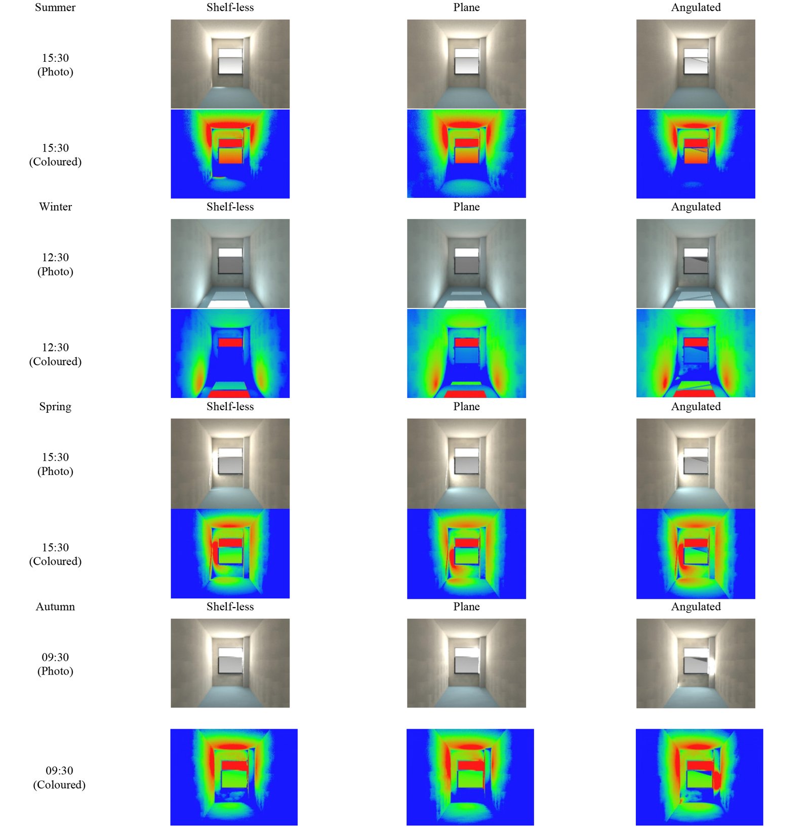
The first phase included three configurations which are shelf-less (without adding the light shelf), plane light shelf and angulated (β is equal to 45°) light shelf. A geometric model of the case room and the external light shelf was created using Relux. The calculations are assessed during the year or at a special time, according to sDA and ASE values; calculated illuminance also provides information about the amount of daylight at four specific dates.
Figure 14 represents the results of average (Eav), minimum (Emin), and maximum (Emax) illuminance on four significant days (March 21, June 21, December 21, and September 21) and at three different hours (09:30, 12:30, 15:30,) for each day. Variations between Emax and Emin show that angulated configuration provides the most evenly distributed daylight at all times in summer, at 15:30 in winter, and at 9:30 in spring. The average illuminance increases from 2580 lux to 2610 lux with the usage of plane configuration on March 21 at 12:30 pm. While plane configuration increases daylight illuminance at a rate of 1.16%, angulated one decreases by 1.16% average illumination level by the same date. This deviation is 0% between shelf-less and plane configurations, and angulated configuration decreases by 2.79% average illumination level for September 23, 12:30. When we compare it with the calculations for shelf-less configuration according to the illuminance, angulated configuration works as a shading device, while plane configuration does not. With respect to these results, the Altmann linkage-based light shelf contributes not only as a light redirecting device but also as a shading device for varying seasons and times.
Figure 14
Fig. 14. Average (Eav), minimum (Emin) and maximum (Emax) illuminance values (in lux) of three configurations at four significant days and at three hours for each day
According to data presented in Figs. 15(a) and (b), any version of the Altmann linkage-based light shelf does not work efficiently in winter since the sunlight angles are quite horizontal (09:30 – elevation: 0.08o, azimuth: 120.52o; 12:30 - elevation: 24.02o, azimuth: 154.2o; 15.30 - elevation: 25.47o, azimuth: 200.43o) in winter. The angulated light shelf only functions as a sunshade in summer because the sunlight angles are quite vertical (09:30 – elevation: 28.9o, azimuth: 81.77o; 12:30 - elevation: 63.49o, azimuth: 116.53o; 15.30 - elevation: 67.92o, azimuth: 233.33o). While the annual sDA value of plane configuration is 73.78%, the value of angulated configuration is 64.54%. In conclusion, all configurations passed the threshold value of sDA (50%) in all seasons. The angulated configuration makes more shading than the plane configuration. Although the annual ASE values of the plane and angulated configurations are very close, they are different at different seasons. Because the ASE value of angulated configuration is 14.47% otherwise, the value of plane configuration is 14.54%. For instance, the plane light shelf causes more sun patches in spring and autumn than the others, while the angulated configuration leads to more sun patches in winter. Similarly, an angulated light shelf results in ASE values of less than 10% in spring and autumn, which makes it more successful than the others in providing shading. Emax values of all light shelf versions have become indicators of sun patch, as they reached 38000 lux (as excluded in Fig. 14) at 12.30 pm in winter and in spring and at 12.30 pm and 15.30 pm in autumn specifically. Appendix A.1 shows the raytracing photographs in which the differences between the three configurations are distinct. Concerning this, the angulated configuration is more reflected than the others.
4.2. The second phase findings
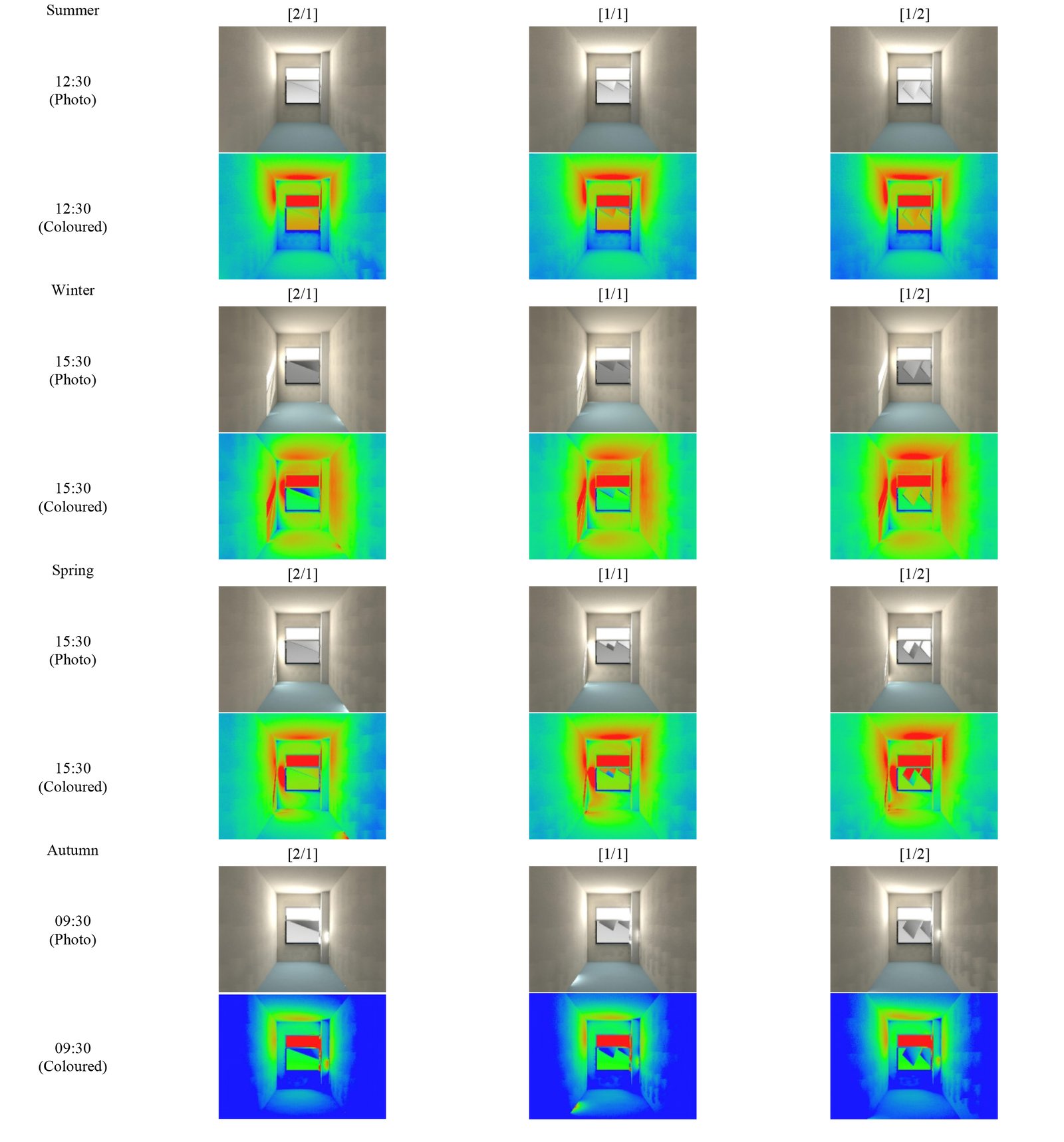
The second phase contained three alternative designs: a rectangle light shelf with 2/1 link length ratio, two square light shelves, and two rectangle light shelves with 1/2 link length ratio. A geometric model of the case room and these three versions were designed in Relux. The Altmann linkage-based light shelves are placed at the outdoor locations again. All designs were prepared for the light shelf’s maximum angle with the west to calculate and analyze daylight shelves in summer, winter, spring, and autumn at 09:30, 12:30, and 15:30. The calculations were assessed during the year or at a special time, according to sDA and ASE values; calculated illuminance provides information about the amount of daylight on four specific dates.
Figure 16 shows the minimum, maximum, and average illuminance values of the three designs. Figure 17 indicates sDA and ASE values for the light shelves. Variations between Emax and Emin show that the [1/1] design provides the most evenly distributed daylight at 09:30 and 12:30 in summer, and the [1/2] design provides the most evenly distributed daylight at 9:30 in autumn. The average illuminance increases from 454 lux to 486 lux using the [1/1] design instead of the [2/1] design at 12:30 pm in summer. Emax values of all light shelf designs have become indicators of sun patches, as they reached 36000 lux (as excluded in Fig. 16) at 12.30 pm in winter, in spring, and at 12.30 pm and 15:30 in autumn, specifically. According to this data, [1/2] design has the highest Eav values in nearly all seasons.
Figure 16
Fig. 16. Average (Eav), minimum (Emin) and maximum (Emax) illuminance values of three designs at four significant days and at three hours for each day.
According to data represented in Figs. 7(a) and (b), any design of the Altmann light shelf does not work efficiently in winter; since the sunlight angles are quite horizontal in winter. All light shelf designs only function as a sunshade in summer because the sunlight angles are quite vertical. The annual sDA values are 65.89% for the [2/1] design, 71.52% for the [1/1] design, and 78.70% for the [1/2] design. In conclusion, all Altmann linkage-based light shelf designs passed the threshold value of sDA (50%) in all seasons. Therefore, [2/1] design makes more shading than the others. The annual ASE values are 10.03% for the [2/1] design, 11.55% for the [1/1] design, and 12.78% for the [1/2] design. Looking at the seasons, they have some differences. For instance, the [1/1] design provides more shading devices at 09:30 in summer and autumn. Similarly, as the [2/1] design results in ASE values of less than 10% in spring and autumn, it is more successful than the others in providing shading. However, the differences between the three designs are distinct when we look at all results and the raytracing photographs in Appendix A.2. The performance of the [1/1] design is better than the others, as it provides both visual comfort and ease of use and can distribute sunlight homogeneously. Therefore, [1/1] design can be preferred.
4.3. The third phase findings
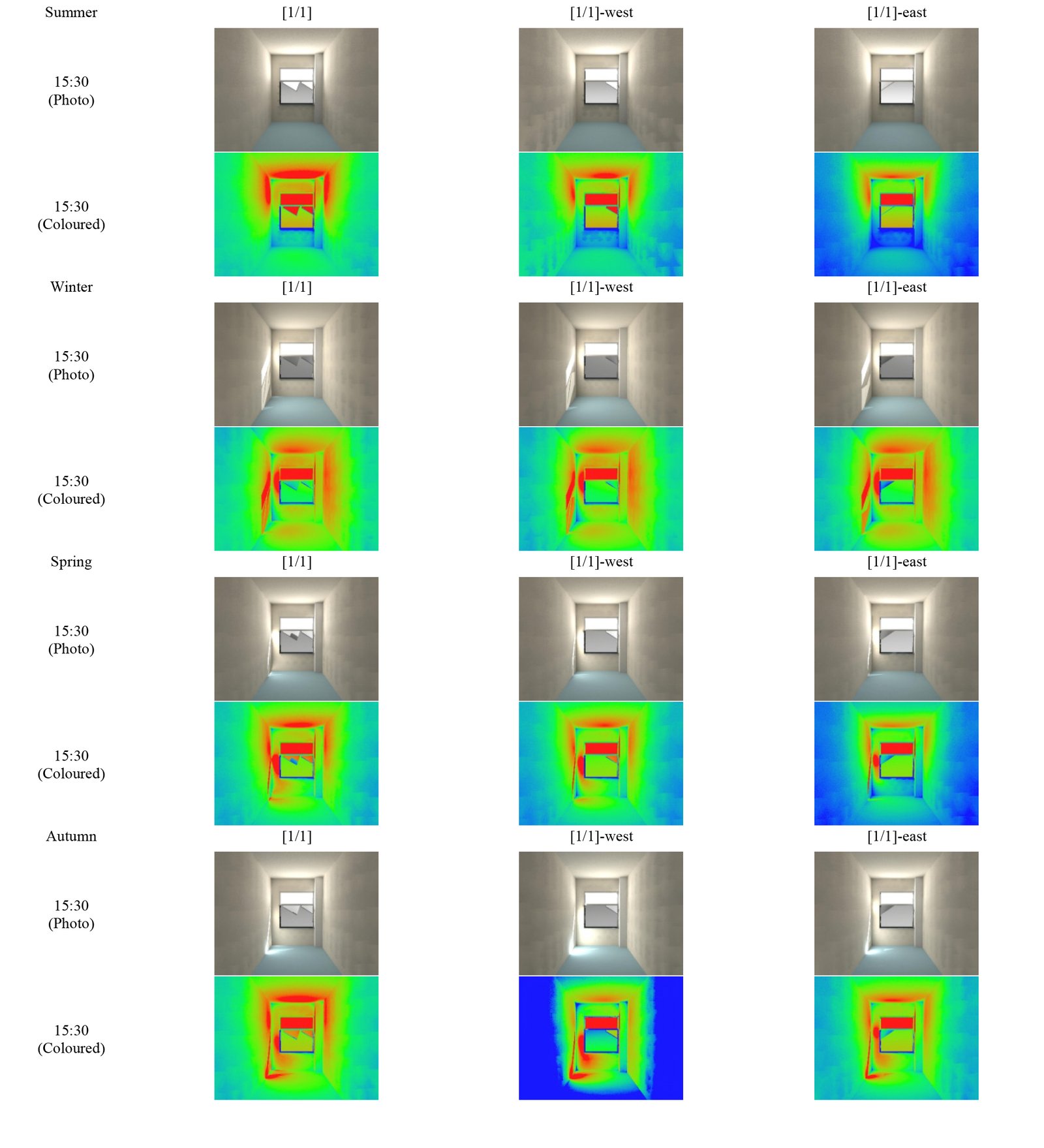
The third phase contained three configurations of the selected design in the second phase, which are [1/1], [1/1]-west, and [1/1]-east. Again, a geometric model of the case room and the three configurations were designed with Relux. The Altmann linkage-based light shelf’s maximum angle with the west and east are prepared as the three configurations to calculate and analyze daylight shelves in Summer, Winter, Spring, and Autumn at 09:30, 12:30, and 15:30. The calculations are assessed during the year or at a special time, according to sDA and ASE values; calculated illuminance provides information about the amount of daylight on four specific dates.
The data in Fig. 18 illustrates the minimum, maximum, and average illuminance values of each design, whereas, Fig. 19 shows sDA and ASE values for three different configurations. Variations between Emax and Emin show that the [1/1] configuration provides the most evenly distributed daylight at 12:30 in summer, the [1/1]-west configuration at 12:30 in autumn and 15:30 in winter, and the [1/1]-east configuration provides the most evenly distributed daylight at 9:30 in autumn. The average illuminance increases from 375 lux to 472 lux and 610 lux using [1/1]-east instead of [1/1]-west and [1/1] at 15:30 in summer. Emax values of all light shelf designs have become indicators of sun patches, as they reached 36000 lux (as excluded in Fig. 18) at 12.30 in winter, in spring, and at 12.30 pm and 15:30 in autumn specifically.
The annual sDA values are 71.52% for the [1/1] design, 72.99% for the [1/1]-west design and 75.92% for the [1/1]-east design. In conclusion, all configurations passed the threshold value of sDA (50%) in all seasons. [1/1]-east makes more shading than the others. The annual ASE values are 8.83% for the [1/1] design, 8.56% for the [1/1]-west design, and 8.22% for the [1/1]-east design. They have some differences in different seasons. For instance, the [1/1] design provides more shading devices at 15:30 in spring. Similarly, as the [1/1]-east design results in ASE values of less than 10% at 15:30 in spring and autumn, it is more successful than the others in providing shading but not directing sunlight. Appendix A.3 includes the raytracing photographs in which the differences between the three configurations are distinct. According to these data, while [1/1] and [1/1]-west designs direct daylight better in the afternoon because of facing west, [1/1]-east design directs daylight better in the morning as it faces east.
5. Conclusion
The focus is to efficiently direct daylight inside with a movable light shelf that can be positioned in various rotating angles corresponding to the movement of the Altmann linkage. Three design phases approach to reach the final design, which has optimum sDA and ASE values. The first design phase represents how the rotation angle to the west and the building change with the mounting of the light shelf with different link length ratios. The second design phase shows the difference between light shelves of different geometric shapes. The final design phase indicates the change in the illuminance value and how the performance of the light shelf changes when the light shelves that can rotate in different directions are rotated according to the direction of the sun. Afterward, daylight analyses were made in the Relux program of the products that came out of all these design stages. The first phase findings include three configurations of the selected design: shelfless, plane, and angulated configurations. Obtaining results show that the annual sDA value of plane configuration is 73.78%, whereas the value of angulated configuration is 64.54%. While the ASE value of angulated configuration is 14.47%, the ASE value of plane configuration is 14.54%. Therefore, the angulated configuration makes more shading than the plane configuration and causes less glare. The second phase finding compares three design alternatives with the link length ratio (2/1, 1/1, 1/2) regarding sDA and ASE values. The [2/1] design has 65.89% sDA and 10.03% ASE values; the [1/1] design has 71.52% sDA and 11.55% ASE values; the [1/2] design has 78.70% sDA and 12.78% ASE values. The final and third phase finding involves calculating sDA and ASE values for three different connections of the [1/1] design. Three different connections allow the movable light shelf to be directed differently.
The analysis reveals that the light shelf, designed by leveraging the diagonal movement of the Altmann linkage, significantly improves the distribution of daylight into the interior space, as indicated by the sDA and ASE values (sDA = 64.54% and ASE = 14.47%). This finding is further corroborated by the light reflections observed in the Raytracing images presented in Appendices A, B, and C, obtained during the Relux simulations.
All design phases aim to achieve the best design by comparing the angles of the light shelves with the west axis and the building. Additionally, the results of the daylight analyses conducted using the Relux software support this data. The results of this study show that the light shelf design, which can rotate in two different directions, is more beneficial for directing sunlight inside. The east and west directions on the south facade are utilized to make the most efficient use of daylight. In this way, we can direct daylight from the east in the morning and from the west in the afternoon into our interior space. Although this study was conducted in the Northern Hemisphere, it will also be beneficial when applied in the Southern Hemisphere. The east and west directions are utilized on the south facade to use daylight most efficiently. This way, we direct the daylight coming from the east in the morning and from the west in the afternoon into our interior space. Although this study is conducted in the Northern Hemisphere, it will also be beneficial when applied in the Southern Hemisphere.
For future studies, this work can be applied to the entire facade of a building. When applied to the whole facade, networks of mechanisms can be designed and used instead of separate mechanisms for each window. It can be integrated into smart building designs by adding automation, allowing the system to move according to the sun's angle.
Appendix A.
Acknowledgement
We would like to express our sincere gratitude to Yasemin Öztürk for her support during the model construction and on-site measurement phases, and to the staff of the İzmir Institute of Technology Carpentry Workshop for their contributions. This study has been supported under the BAP (Scientific Research Projects) framework. Korkmaz K., Atarer F. “Design and Performance Analysis of Light Shelves using Altmann Mechanism” 2017IYTE70 (2018-2021).
Contributions
F. Atarer: Conceptualization, Methodology, Investigation, Visualization, Formal analysis, Calculation & Analysis, Writing – Original Draft, Writing – Review & Editing. Z. Tuğçe Kazanasmaz: Conceptualization, Methodology, Investigation, Writing – Review & Editing. K. Korkmaz: Methodology, Investigation, Writing – Review & Editing. G. Kiper: Methodology, Calculation & Analysis, Investigation, Writing – Review & Editing.
Declaration of competing interest
The authors declare no conflict of interest.
References
- I. Turan, A. Chegut, D. Fink, C. Reinhart, The Value of Daylight in Office Spaces, Building and Environment, 168 (2020) 106503. https://doi.org/10.1016/j.buildenv.2019.106503
- H. Y. S. Christopher, T. K. L. Louis, F. S. F. Sharifah, Daylighting Performance of Integrated Light Shelf with Horizontal Light Pipe System for Deep Plan High-Rise Office in Tropical Climate, Journal of Daylighting 9 (2022) 83-96. https://doi.org/10.15627/jd.2022.6
- A. Kontadakis, A. Tsangrassoulis, L. Doulos, S. Zerefos, A Review of Light Shelf Designs for Daylit Environments, Sustainability 10, 71, (2018). https://doi.org/10.3390/su10010071
- M.N. Assimakopoulosa, R.F. Masib, F. Rossic, A. Ferranted, A. Fotopoulou, D. Papadakia, S. Ruggierob, G.P. Vanolie, Application of light shelves in a refurbished student dormitory Energy, lightings and comfort aspects, 6th International Conference on Advances on Clean Energy Research, ICACER 2021 April 15-17, 2021, Barcelona, Spain. https://doi.org/10.1016/j.egyr.2021.06.043
- S. Ruggiero, M.N. Assimakopoulos, R.F. Masi, F. Rossi,. Fotopoulou, D. Papadaki, G.P. Vanoli, A. Ferrante, Multi-Disciplinary Analysis of Light Shelves Application within a Student Dormitory Refurbishment, Sustainability, 13, 8251 (2021). https://doi.org/10.3390/su13158251
- A. Meresi, Evaluating daylight performance of light shelves combined with external blinds in south-facing classrooms in Athens, Greece, Energy & Buildings, 116, (2016) 190-205. https://doi.org/10.1016/j.enbuild.2016.01.009
- A.E. Moghadam, P. Ildarabadi, K. Aliakbari, A. Arabkoohsar, F. Fadaee, Performance analysis of light shelves in providing visual and thermal comfort and energy savings in residential buildings, Journal of the Brazilian Society of Mechanical Sciences and Engineering 42:484 (2020). https://doi.org/10.1007/s40430-020-02565-2
- M. Brzezicki, An Evaluation of Useful Daylight Illuminance in an Office Room with a Light Shelf and Translucent Ceiling at 51o N, Buildings 11 (11) 494. (2021). https://doi.org/10.3390/buildings11110494
- Y.W. Lim, C. Y. S. Heng, Dynamic internal light shelf for tropical daylighting in high-rise office buildings, Building and Environment 106 (2016). https://doi.org/10.1016/j.buildenv.2016.06.030
- N. Ziaee, R. Vakilinezhad, Multi-objective optimization of daylight performance and thermal comfort in classrooms with light-shelves: Case studies in Tehran and Sari, Iran, Energy and Buildings 254 (5) (2022) 111590. https://doi.org/10.1016/j.enbuild.2021.111590
- A.A.S. Bahdad, S.F.S. Fadzil, H.O. Onubi, S.A. BenLasod, Sensitivity analysis linked to multi-objective optimization for adjustments of light-shelves design parameters in response to visual comfort and thermal energy performance, Journal of Building Engineering 44 (1) (2021) 102996. https://doi.org/10.1016/j.jobe.2021.102996
- A.A.S. Bahdad, S.F.S. Fadzil, N. Taib, Optimization of Daylight Performance Based on Controllable Light-shelf Parameters using Genetic Algorithms in the Tropical Climate of Malaysia, Journal of Daylighting 7(1) (2020) 122-136. https://doi.org/10.15627/jd.2020.10
- C. Kurtay, O. Esen, A new method for light shelf design according to latitudes: CUN-OKAY light shelf curves, Journal of Building Engineering 10 (2017) 140-148. https://doi.org/10.1016/j.jobe.2017.02.008
- U. Berardi, H. K. Anaraki, The benefits of light shelves over the daylight illuminance in office buildings in Toronto, Indoor and Built Environment 27(2) (2018) 244-262.
- R.A. Mangkuto, F. Feradi, R.E. Putra, R.T. Atmodipoero, F. Favero, Optimisation of daylight admission based on modifications of light shelf design parameters, Journal of Building Engineering 18 (2018) 195-209. https://doi.org/10.1016/j.jobe.2018.03.007
- P. Bakmohammadi, E. Noorzai, Investigating the optimization potential of daylight, energy and occupant satisfaction performance in classrooms using innovative photovoltaic integrated light shelf systems, Science and Technology for the Built Environment 28 (11) (2021) 467-482. https://doi.org/10.1080/23744731.2021.2014247
- A. A. S. Bahdad, S. F. S. Fadzil, H. O. Onubi, S. A. BenLasod, Multi‑dimensions optimization for optimum modifications of light‑shelves parameters for daylighting and energy efficiency, International Journal of Environmental Science and Technology 19 (2022) 2659-2676. https://doi.org/10.1007/s13762-021-03328-9
- A. M. Qahtan, A. S. S. Bahdad, N. Al-Tamimi, S. F. S. Fadzil, Optimizing daylighting in lecture halls within hot-arid climates through modification of glazing systems with light-shelves: A parametric design approach. Indoor and Built Environment 33(5) (2024) 929-956. https://doi.org/10.1177/1420326X241226651
- A. Tabadkani, A. Roetzel, H.X. Li, A. Tsangrassoulis, Design approaches and typologies of adaptive facades: A review, Automation in Construction 121 103450 (2021). https://doi.org/10.1016/j.autcon.2020.103450
- S.Q. Sadegh, E. Gasparri, A. Brambilla, A. Globa, Kinetic facades: An evolutionary-based performance evaluation framework, Journal of Building Engineering 53 104408 (2022). https://doi.org/10.1016/j.jobe.2022.104408
- S.M. Hosseini, M. Mohammadi, T. Schroeder, O.G. Santin, Integrating interactive kinetic façade design with colored glass to improve daylight performance based on occupants' position, Journal of Building Engineering 31 101404. (2020). https://doi.org/10.1016/j.jobe.2020.101404
- L.L. Thanh, T.L. Duc, H.N. Minh, Q.H. Nguyen, H.N. Xuan, Optimal design of an Origami-inspired kinetic façade by balancing composite motion optimization for improving daylight performance and energy efficiency, Energy 219 119557 (2021). https://doi.org/10.1016/j.energy.2020.119557
- S.M. Hosseini, S. Heidari, General morphological analysis of Orosi windows and morpho butterfly wing's principles for improving occupant's daylight performance through interactive kinetic façade, Journal of Building Engineering 59(1) (2022) 105027. https://doi.org/10.1016/j.jobe.2022.105027
- S.H. Han, Energy Sustainability of an Integrative Kinetic Light Shelf Unit, KIEAE Journal, 15 (3) 2015, 15-20. https://doi.org/10.12813/kieae.2015.15.3.015
- H. Lee, S. Gim, J. Seo, Y. Kim, Study on movable light-shelf system with location-awareness technology for lighting energy saving, Indoor and Built Environment, 26 (6) (2016) 1-17. https://doi.org/10.1177/1420326X16659691
- H. Lee, S. Kim, J. Seo, Evaluation of a light shelf based on energy consumption for lighting and air conditioning, Indoor and Built Environment 27 (10) (2017) 1405-1414. https://doi.org/10.1177/1420326X17719954
- H. Lee, H. Jang, J. Seo, A preliminary study on the performance of an awning system with a built-in light shelf, Building and Environment 131 (2018) 255-263. https://doi.org/10.1016/j.buildenv.2018.01.016
- H. Lee, Performance evaluation of a light shelf with a solar module based on the solar module attachment area, Building and Environment 159 106161 (2019).
- A.A.S. Bahdad, , S.F.S. Fadzil, N. Taib, Evaluating kinetic light-shelves and their impacts on daylighting performance, Indonesian Journal of Electrical Engineering and Computer Science 19 (1) 4 (2020) 76 - 484. https://doi.org/10.11591/ijeecs.v19.i1.pp476-484
- X. Zhao, J. Seo, H. Lee, Performance evaluation of a light shelf with a folding reflector (LSFR) to improve daylighting performance, Building and Environment 255 111457 (2024). https://doi.org/10.1016/j.buildenv.2024.111457
- F.G. Altmann, Über raümliche sechsgliedrige Koppelgetriebe, Sonderdruck aus derZeifschrift des Vereines Deutscher Ingenieure 96(8) (1954) 245-249.
- J. M. McCarthy, G. S. Soh, Geometric Design of Linkages, 2nd Edition, Springer: New York, NY, 2011. https://doi.org/10.1007/978-1-4419-7892-9
- J. E. Baker, A Geometrico-Algebraic Exploration of Altmann's Linkage, Mechanism and Machine Theory 28 (2) (1993) 249-260. https://doi.org/10.1016/0094-114X(93)90091-9
- S. Xiaoke, H. Guo, B. Li, R. Liu, Z. Deng, Large Deployable Network Constructed by Altmann Linkages, Proceedings of the Institution of Mechanical Engineers Part C Journal of Mechanical Engineering Science 231 (2) (2016) 341-55. https://doi.org/10.1177/0954406215626955
- F. Atarer, K. Korkmaz, G. Kiper, Design Alternatives of Network of Altmann Linkage, International Journal of Computational Methods and Experimental Measurements 5(4) (2017) 495-503. doi:10.2495/CMEM-V5-N4-495-503. https://doi.org/10.2495/CMEM-V5-N4-495-503
- G. Yıldız, Design of Deployable Structures Comprising Modified Altmann Linkage, Ms. Thesis in Mechanical Engineering in IZTECH (2020).
- M.H. Moazzeni, Z. Ghiabaklou, Investigating the Influence of Light Shelf Geometry Parameters on Daylight Performance and Visual Comfort, a Case Study of Educational Space in Tehran, Iran, Buildings 6 (3) 26 (2016). https://doi.org/10.3390/buildings6030026
- IES Approved Method: Spatial Daylight Autonomy and Annual Sunlight Exposure, (2012). IES LM-83e12, USA.
Copyright © 2024 The Author(s). Published by solarlits.com.
 HOME
HOME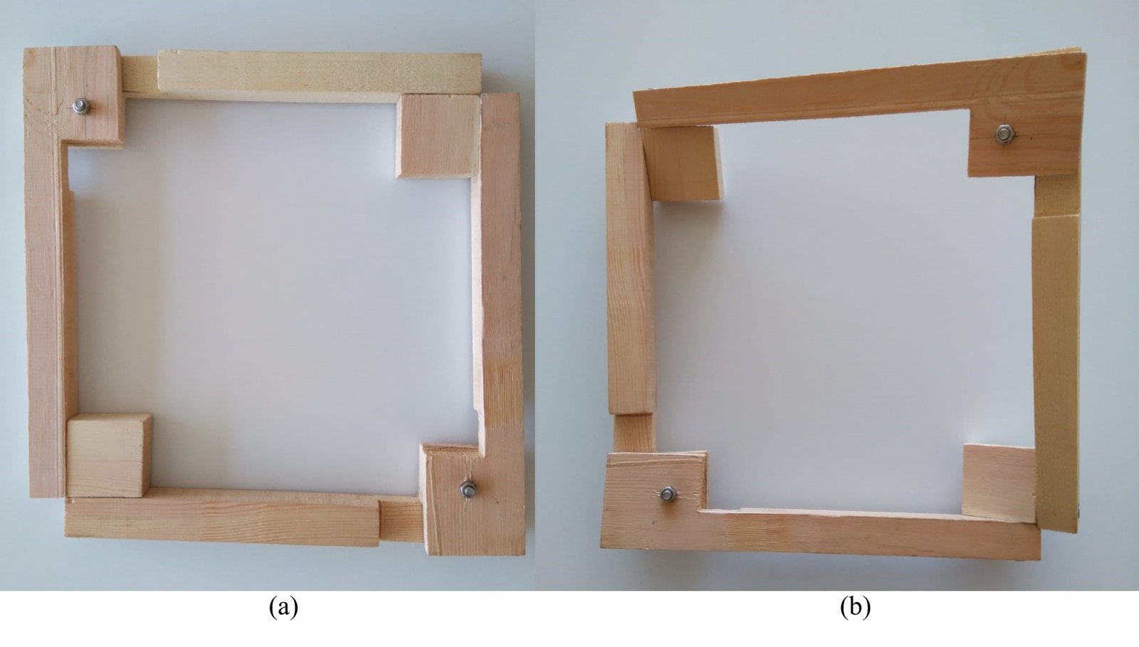 Figure 1
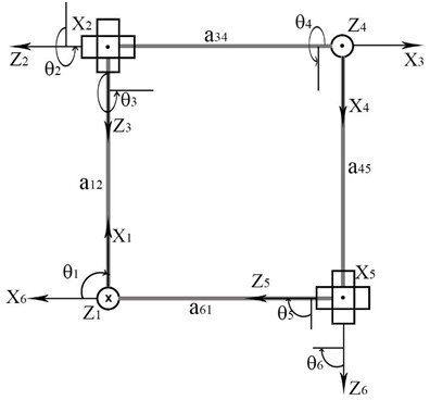 Figure 2
 Figure 3
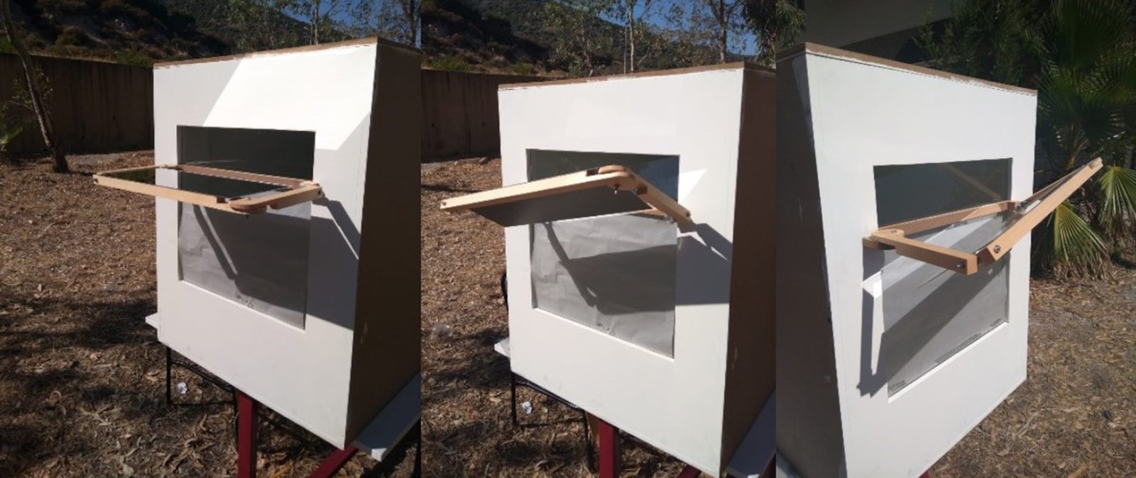 Figure 4
 Figure 5
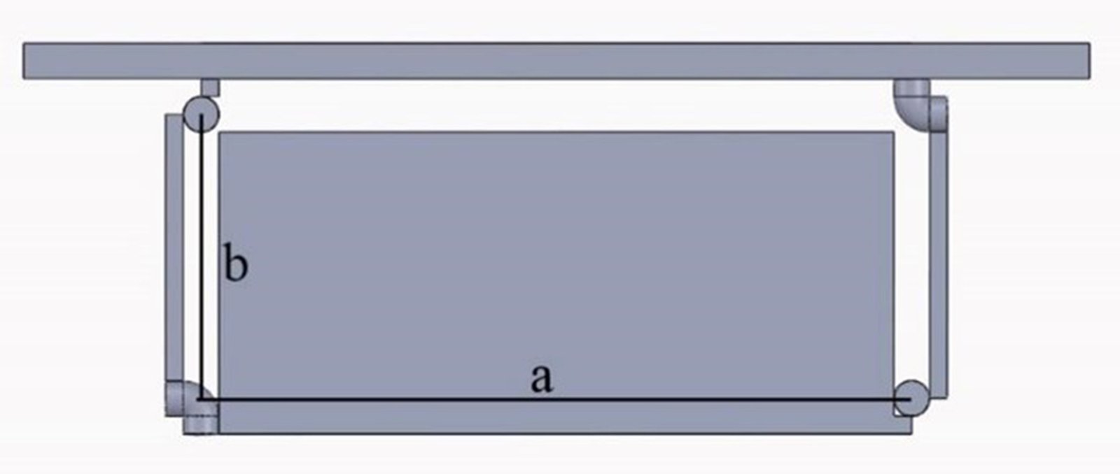 Figure 6
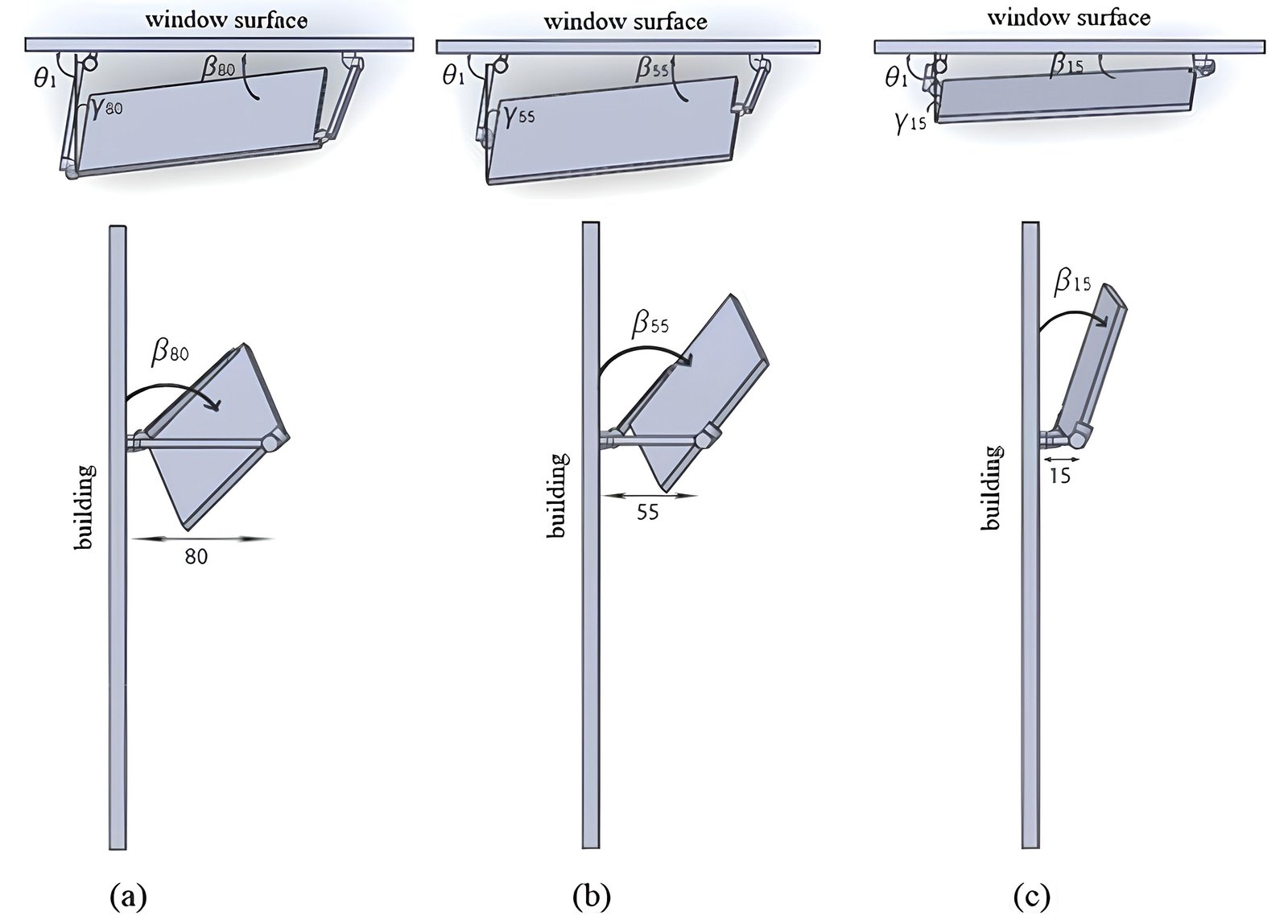 Figure 7
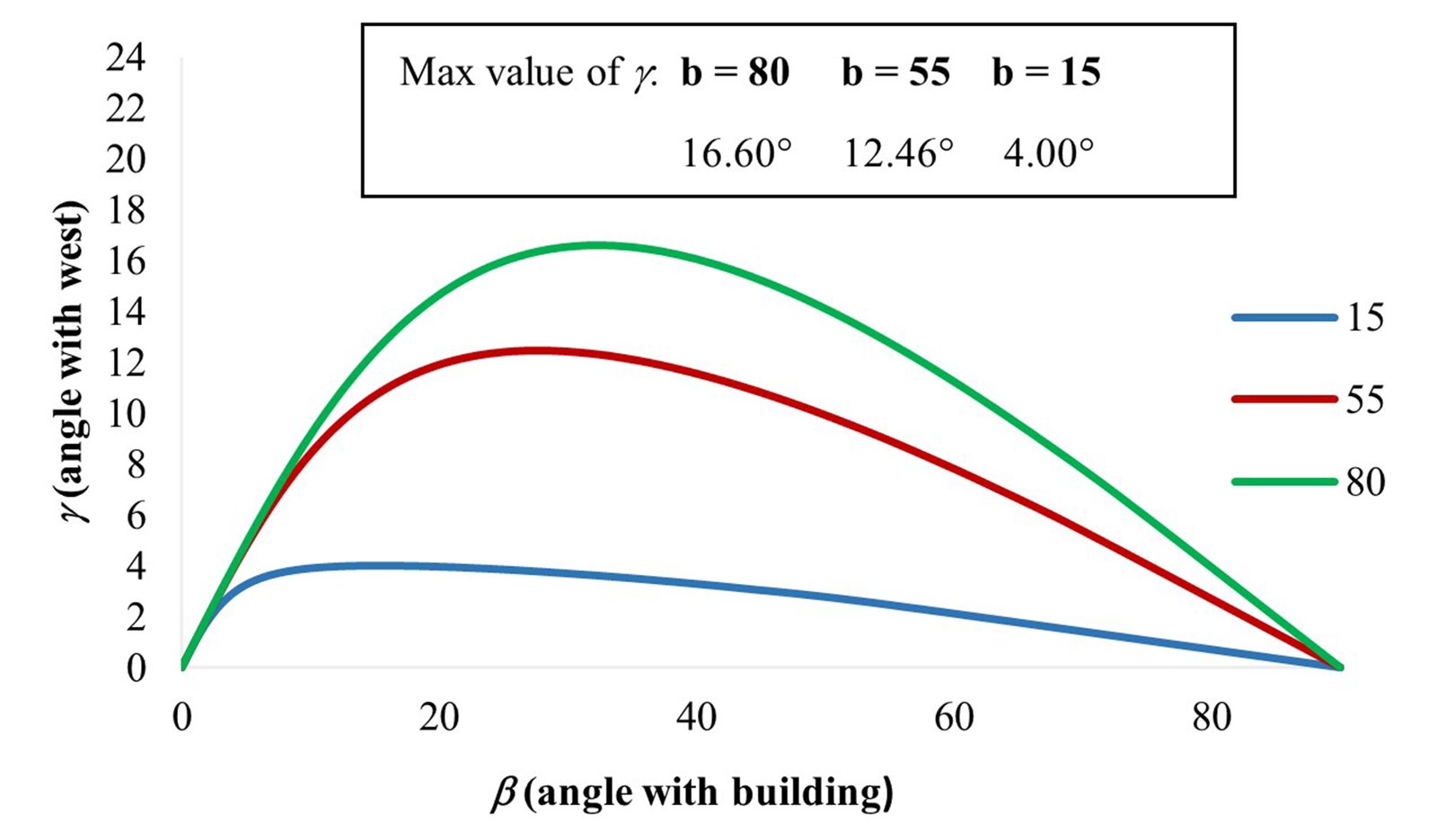 Figure 8
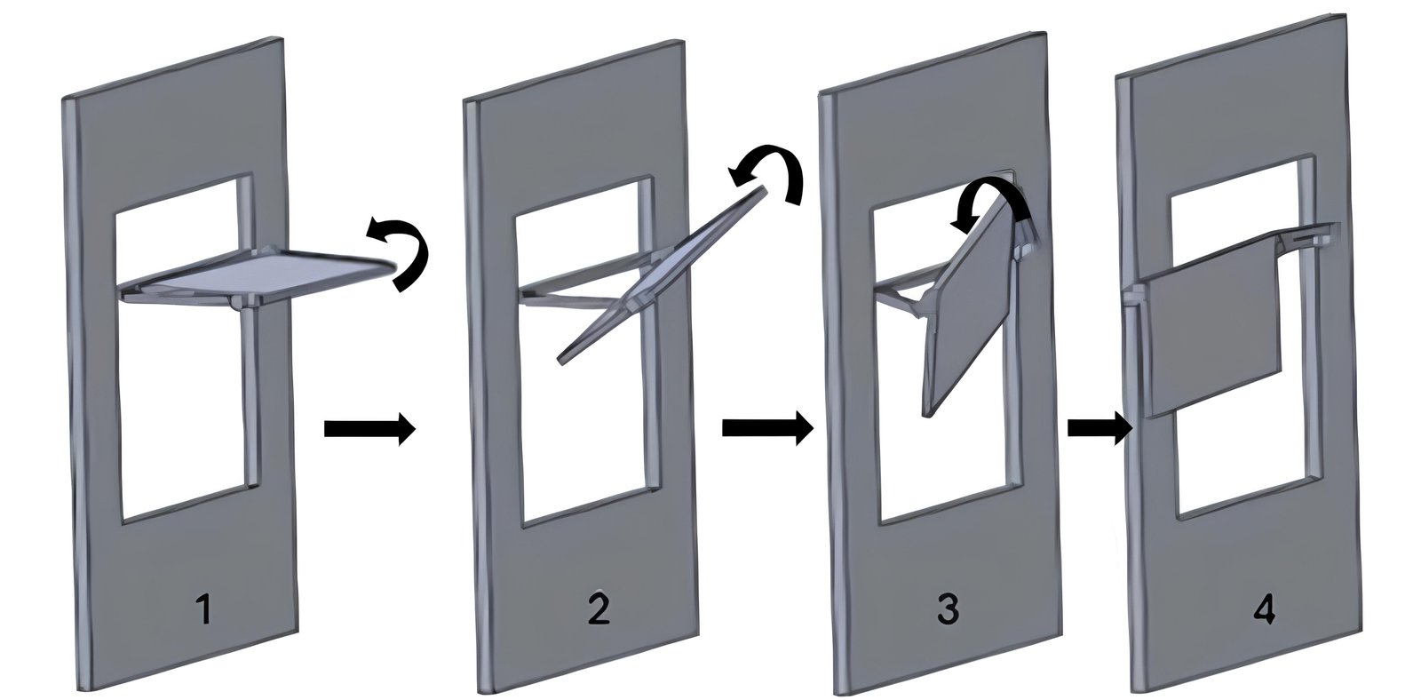 Figure 9
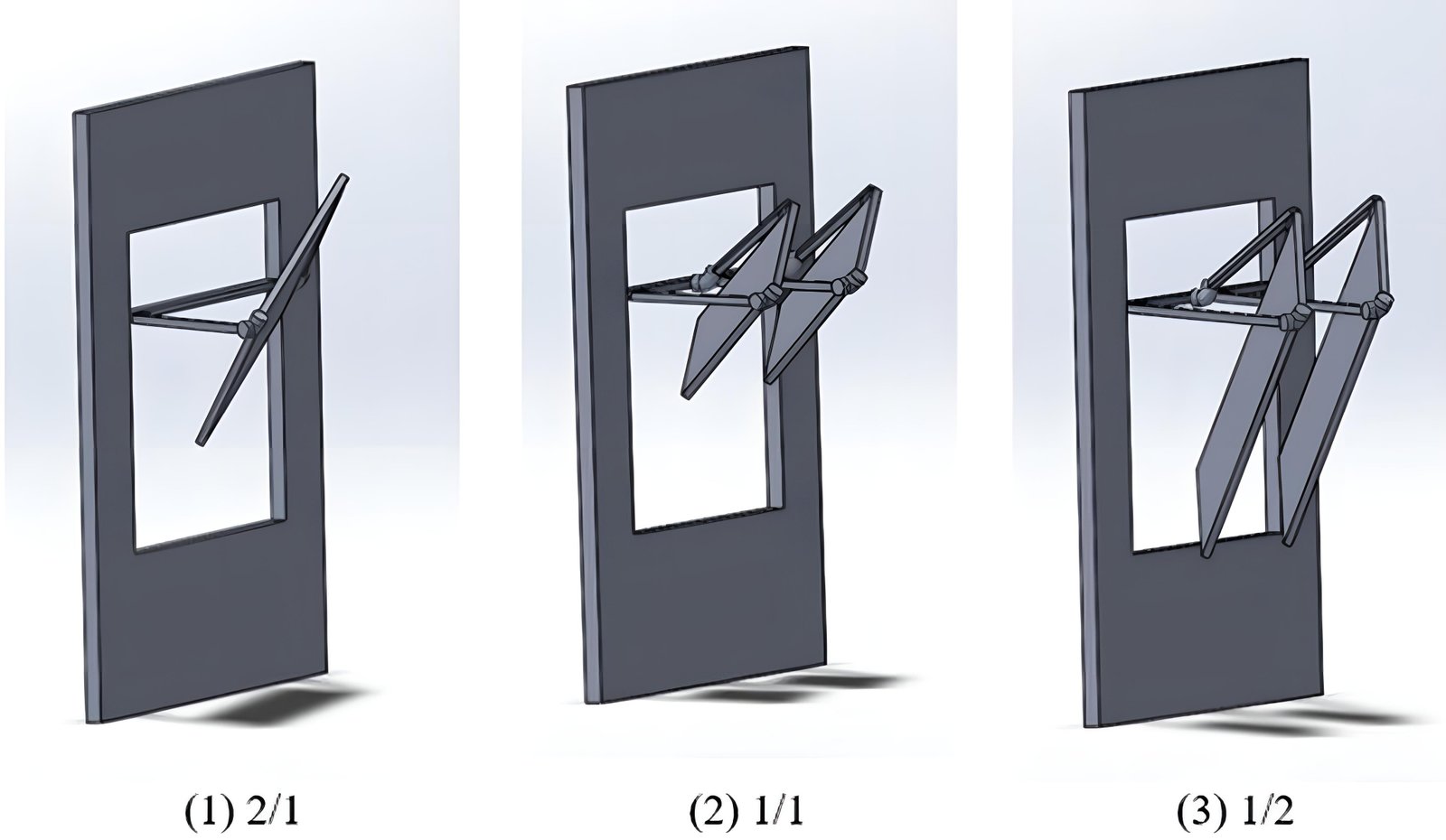 Figure 10
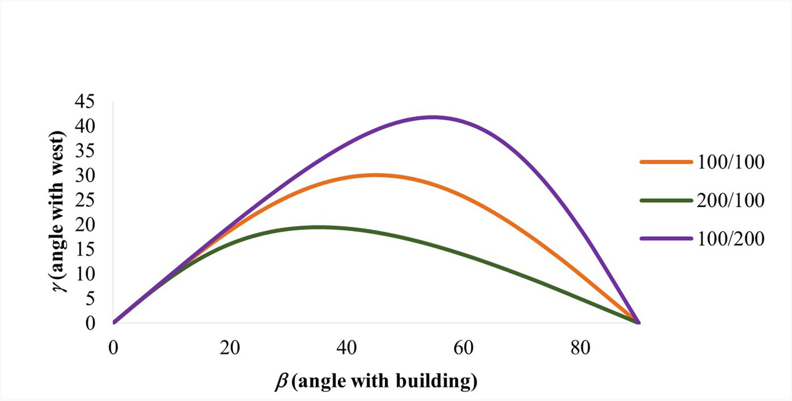 Figure 11
 Figure 12
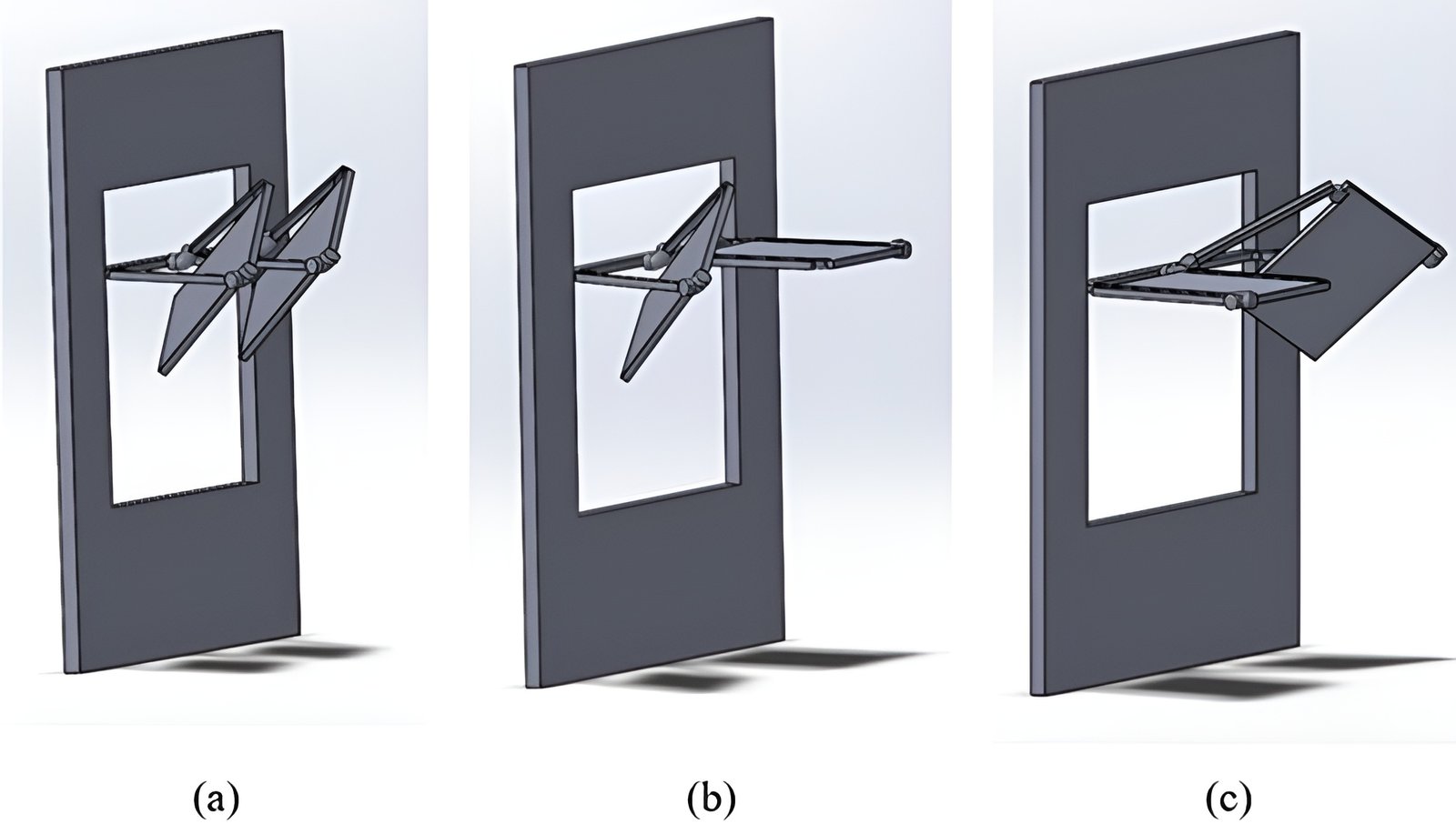 Figure 13
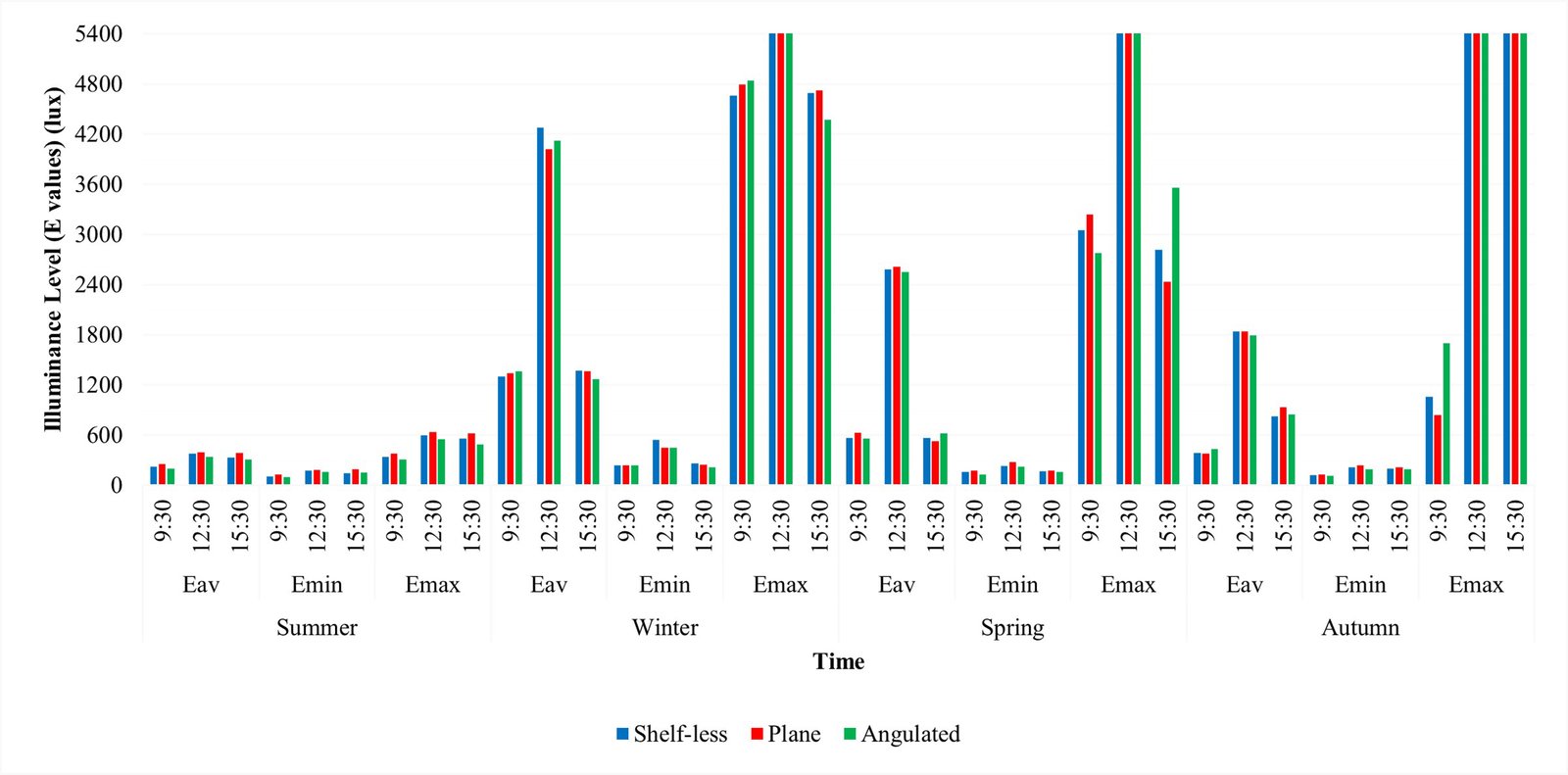 Figure 14
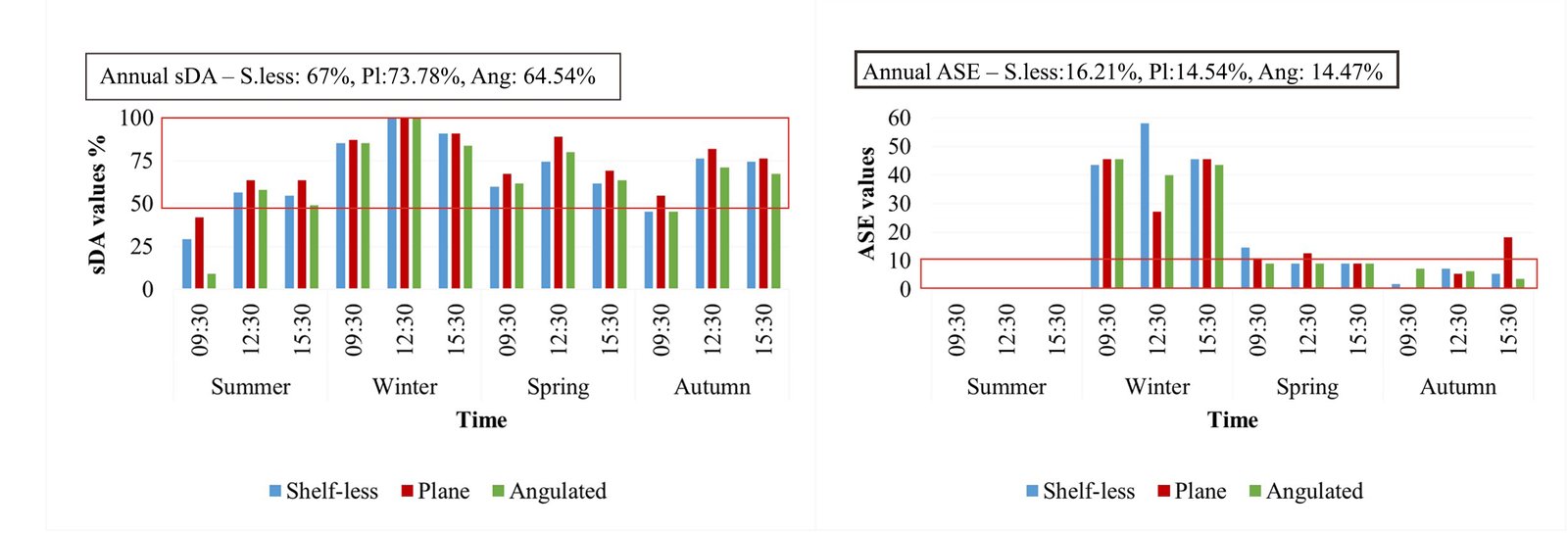 Figure 15
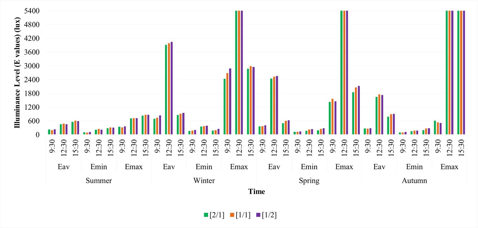 Figure 16
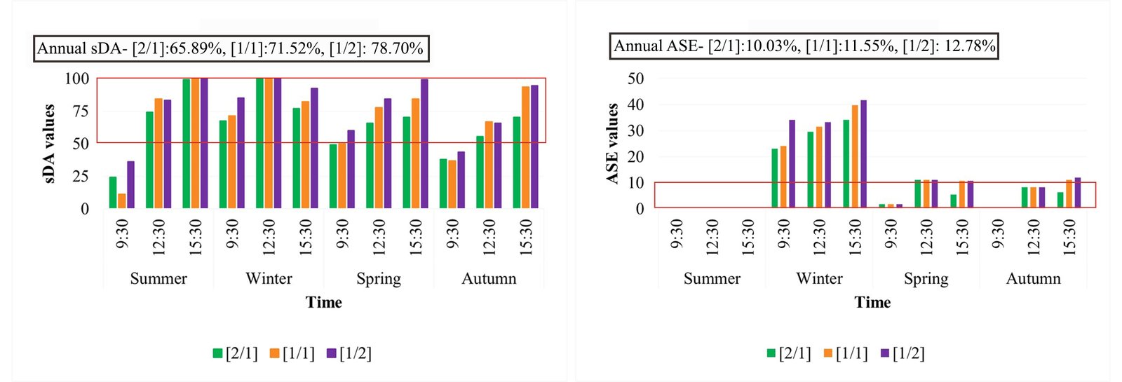 Figure 17
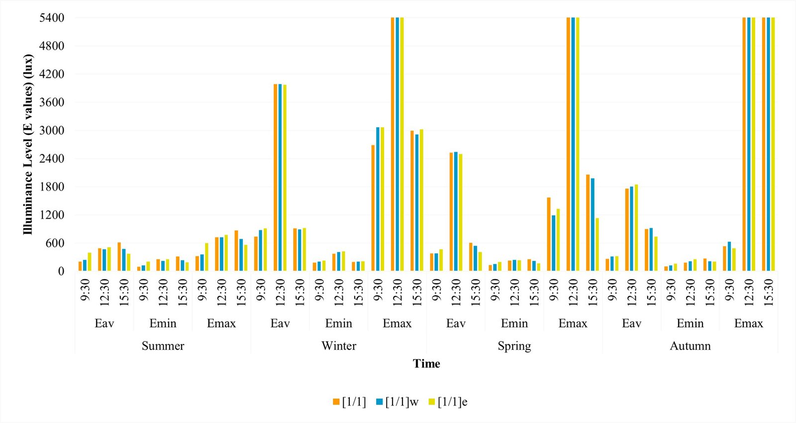 Figure 18
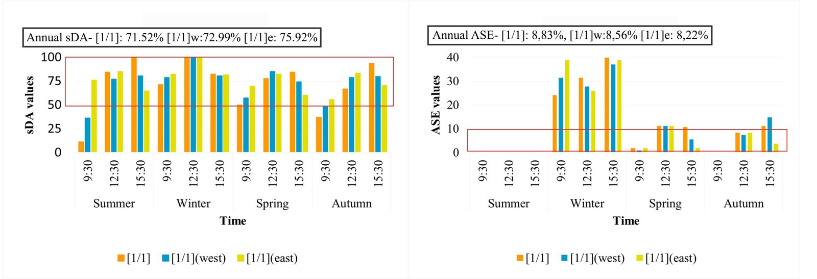 Figure 19
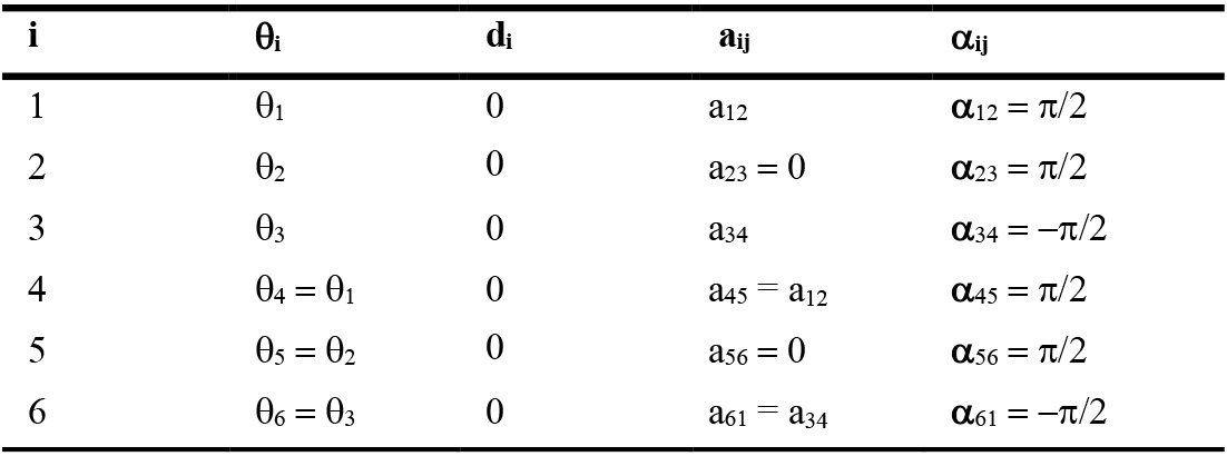 Table 1
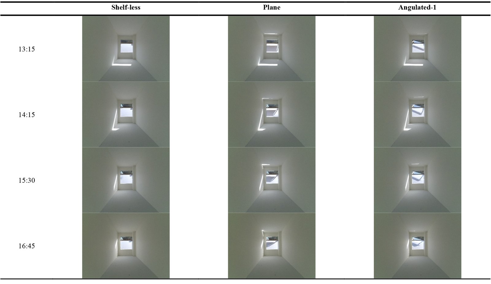 Table 2
 Table 3
 Table 4
 Table 5
 Table 6
 Table 7
 Table 8