
Rizki A. Mangkuto,1,* Ikhwan Muttaqien Hermawan,2 Tiara Nurhuda2,3
Author affiliations
1Built Environment Performance Engineering Research Group, Faculty of Industrial Technology, Institut Teknologi Bandung, Bandung, 40132, Indonesia
2Engineering Physics Program, Faculty of Industrial Technology, Institut Teknologi Bandung, Bandung, 40132, Indonesia
3Industrial Engineering Program, Faculty of Engineering, Universitas Insan Cendekia Mandiri, Bandung, 40162, Indonesia
*Corresponding author.
rizkiam2002@itb.ac.id (R. A. Mangkuto)
ikhwan6565@gmail.com (I. M. Hermawan)
tnurhuda@gmail.com (T. Nurhuda)
History: Received 17 March 2026 | Revised 20 April 2026 | Accepted 21 April 2026 | Published online 26 May 2026
2383-8701/© 2026 The Author(s). Published by solarlits.com. This is an open access article distributed under the terms and conditions of the Creative Commons Attribution 4.0 License.
Citation: Rizki A. Mangkuto, Ikhwan Muttaqien Hermawan, Tiara Nurhuda, Closed-form analytical formulation of lighting design objectives procedure in rooms with an isotropic light source, Journal of Daylighting, 13:1 (2026) 285-299. doi: 10.15627/jd.2026.16
Abstract
Mean room surface exitance (MRSE), which indicates the amount of ambient illuminance in a room, is an important parameter in contemporary lighting design objectives (LiDOs) procedures. However, the fundamental MRSE model does not provide explicit relations with the light source characteristics. For the case of an isotropic light source, whose luminous intensity is constant, it is hypothesised that the direct flux on each surface can be accurately computed by first determining the solid angle. This study aims to provide closed-form analytical formulation for computing MRSE using LiDOs procedure in rooms with an isotropic light source. Theoretical calculations are provided and verified to demonstrate the equality of specified and actual MRSE in various room scenarios. Monte Carlo simulations with 1000 random combinations are conducted to parametrically explore the design outcomes. Results suggest that the intended ambient illumination can always be achieved, indicated by the equality between the specified and actual MRSE, due to exact computation of the direct flux received by each surface within the room. This study proposes a new insight on lighting design objectives procedure under the design constraint of isotropic light source, and how MRSE can be related with the relevant input variables to achieve the design objectives.
Keywords
closed-form analytical formulation, isotropic light source, lighting design objectives, mean room surface exitance
Nomenclature
| Aj | area of the j-th surface in the room |
| E(tgt(d), j) | direct illuminance on the j-th surface in the room |
| F(d), j | direct luminous flux received on the j-th surface in the room |
| FRFrs | first reflected flux of the entire room surfaces as calculated by the MRSEspec and ΣAα |
| FRFtgt | first reflected flux of the entire room surfaces as calculated from the MRSEspec and TAIR |
| IΩ | luminous intensity of a source at a given solid angle Ω |
| LiDOs | lighting design objectives |
| Mj | luminous exitance of the j-th surface in the room |
| MRSEact | mean room surface exitance as actually obtained from the LiDOs calculation |
| MRSEfund | mean room surface exitance as calculated from the Duff’s equation |
| MRSEspec | mean room surface exitance as specified by the designer |
| rand | uniformly distributed random number between 0 and 1 |
| TAIR | target/ambient illuminance ratio |
| x, y, z | three-dimensional coordinate of the light source in the room |
| ρj | reflectance of the j-th surface in the room |
| ΣAα | total room area that absorbs light |
| Ωj | solid angle subtended between the source and the j-th surface in the room |
1. Introduction
In contemporary practice of architectural lighting design, the use of lighting design objectives (LiDOs) procedure [1,2] has gained international attention (e.g., [3-7]), as it aims to provide the intended spatial brightness, ambient illumination, visual emphasis, and visual efficiency within a room, tailored to the needs of the room occupants. These are not necessarily bound to the horizontal workplane and its task illuminance, as opposed to the traditional approach of general lighting design. In applying the LiDOs procedure, one of the key parameters that should be specified thoughtfully by the lighting designers or practitioners is the mean room surface exitance (MRSE), which principally indicates the amount of ambient illuminance averaged across the entire room surface, which can be related to the level of spatial brightness [8-10].
While the name of LiDOs procedure itself was coined just recently, the MRSE concept was proposed much earlier [11-13]. In its original form, MRSE can be approximated as a ratio between the total first reflected flux of the entire room surfaces (FRF) and the total room area absorbing light (ΣAα). However, a more fundamental model was later proposed [14,15] to describe MRSE as the weighted average of luminous exitance of the entire room surfaces, as the name implies. While the fundamental MRSE model had been validated, it does not provide an explicit relation between the light source characteristics as the input variables and the MRSE itself as the output variable, as shown in the following subsection.
1.1. MRSE definition
The fundamental definition of MRSE was proposed in literature [14,15], as the weighted average of luminous exitance of the entire room surfaces Aj. It reads:
where Mj is the luminous exitance of each surface and
1.2. MRSE approximation
In a cuboid room where each of the six interior surfaces has a different surface reflectance, the MRSE can be approximated [11,12] using direct illuminances at several grids on the room surfaces, such that:
where FRF is the total first reflected flux of the entire room surfaces, ΣAα is the total room absorption, ρj, Aj, F(d),j, and Etgt(d),j is respectively the surface reflectance of, surface area of, direct flux received by, and direct illuminance on the j-th grid or surface in the room. The Cuttle’s approximation is particularly useful because the MRSE can now be expressed as a function of the light source characteristics, which in this case is the direct flux component.
The accuracy of Equation (2) depends on the number of grids involved. The Fd for each grid is approximated as product of direct illuminance received by each grid and its surface area, and the FRF is simply the sum of each ρjF(d,j). The obtained MRSE value is thus an approximation, as it depends on the n value, and it is not directly derived from the surface luminous exitance (Mj). Moreover, a light source is typically characterised by its luminous intensity (IΩ) in various directions. The F(d),j and are related by the subtended solid angle (Ω) between the source and the surface. However, recent literature on the LiDOs procedure [1,2,16,17] did not specifically describe how to translate the LiDOs parameters, such as MRSE and target/ambient illuminance ratio (TAIR), to the required luminous intensity distribution of the light source(s).
For the specific case of an isotropic light source, whose IΩ is constant (Fig. 1), it is hypothesised that the F(d),j can be accurately computed by first determining the relevant Ω. While considered hypothetical, the knowledge of this specific case can be useful for educational purposes, particularly for showing the theoretical impact of devising luminous flux from a light source with a known intensity distribution. To the best of the authors’ knowledge, detailed discussion on this matter is still limited in literature.
Figure 1
![Illustration of actual luminaire products resembling isotropic light sources [18]; reused with permission.](https://cdn.solarlits.com/solarlits/journals/jd/legacy-manuscripts/figures/13-285-1.jpg)
Fig. 1. Illustration of actual luminaire products resembling isotropic light sources [18]; reused with permission.
Therefore, this study aims to provide closed-form analytical formulation for MRSE in scenarios with isotropic light source, for applying LiDOs procedure and computing the MRSE in such cases, using solid angles subtended between an isotropic light source and the room surfaces, and to determine the applicability of the proposed method in various scenarios. To achieve the objectives, analytical expressions of solid angles are to be derived, from which the actual MRSE values are computed and compared to the specified values, for scenarios without and with interior objects. Monte Carlo simulations are conducted to demonstrate the equality of specified and actual MRSE, as well as to parametrically explore the design combinations in both scenarios.
2. General concept and methods
2.1. LiDOs procedure
The LiDOs procedure is started by specifying the desired MRSE value (hereinafter MRSEspec), based on intended spatial brightness of the room [12-14]. For a room with n number of surfaces with difference reflectance ρj, where each surface has an area Aj, the required first reflected flux of the entire room surfaces (FRFrs) can be estimated based on Cuttle’s approximation in Equation (2) as follows:
It should be noted that MRSEspec in LiDOs procedure is assumed constant or uniform throughout the interior space and is numerically equal to the average indirect illuminance in a sphere, according to the Sumpner’s principle [19], and is acknowledged to be the main limitation in the entire procedure. Nevertheless, while the results are thus inexact, the errors are mostly acceptable for typical room lighting scenarios, i.e. < 10% for downlight luminaires and < 20% for uplight luminaires [15]. The next step of the LiDOs procedure is assigning the intended TAIR for each surface, which is the ratio between the target total illuminance received on the surface (Etgt,j) and the MRSE. The detailed formulae are provided in [16,17].
On each surface, multiplying the direct illuminance Etgt(d),j with the corresponding Aj gives the direct flux received on that surface, i.e. F(d),j. Multiplying F(d),j with ρj gives the first reflected flux from that surface. The sum of the first reflected flux from each surface is called FRFtgt, which can be shown to be:
knowing that MRSEspec is a constant. The FRFtgt is not necessarily equal to FRFrs, since the equality depends on the choice of TAIR values for each surface. The ratio between FRFtgt and the ΣAα is hereinafter called the actual MRSE (MRSEact), which reads:
Consequently, MRSEact is also not necessarily equal to MRSEspec. It is the task of the lighting designer to equal MRSEact with MRSEspec, meaning that the actual design outcome can achieve the initially specified objective. This can be done by tuning the input design variables.
Mathematically, this means the designer should ensure that MRSEact= MRSEspec. By substituting FRFtgt in Equation (5) with that in Equation (4), one gets:
Thus, to ensure that MRSEact= MRSEspec, one needs to satisfy the following equation:
To do so, let us express TAIRj in terms of Fd,j. The latter can be estimated as product of the zonal average luminous intensity of the light source (IΩav,j) and the solid angle subtended between the source and the surface in question (Ωj), such that:
where dωj is the differential element of the solid angle subtended between the source and each differential surface area. From Equation (4), one can now express TAIRj such that:
Thus, the left-hand side of Equation (10) can now be expressed as follows:
2.2. Isotropic light source
In the special case of an isotropic light source, the luminous intensity I is constant at any direction. The IΩ(av),j in Equation (10) therefore becomes equal to I, which is a constant, such that the equation can be simplified into:
However, to ensure that MRSEact= MRSEspec, one needs to satisfy Equation (10), which leads to:
Solving for I therefore yields:
Equation (13) gives the amount of luminous intensity (in cd) that shall be provided by the isotropic light source, to achieve the intended MRSEspec. Since the total solid angle subtended by the source is 4π sr, the total luminous flux emitted by the source is thus 4πI lm.
Now, to observe the connection with the fundamental definition of MRSE, which is defined in Equation (1), let us express Mj in Equation (1) in terms of MRSEspec. The Mj is the product between ρj and Etgt,j. but the latter can be expressed as the product between TAIRj and MRSEspec. Combining these relations, while again assuming that the MRSEspec is a constant, give:
The resulting fundamental MRSE (hereinafter MRSEfund), based on Equation (1), is thus:
To show that MRSEspec is equal to MRSEfund, it is necessary to show that ΣρjAjTAIRj is equal to ΣAj. This can be done as follows. Let us recall Equation (9) and acknowledge the fact that for the case of isotropic light source, IΩ(av),j = I, which is a constant. By substituting the TAIRj, one can now write:
By substituting the first term on the right-hand side of Equation (16) with the equivalent term in Equation (12), one can now write:
Therefore, Equation (15) simplifies into MRSEfund = MRSEspec as expected.
2.3. Solid angle computation
It is now necessary to compute Ωj, which is the solid angle subtended between the source and each surface in the room, which depends on the position of the source within the room itself. Consider a scenario where the isotropic light source S is located at random coordinate (xS, yS, zS) = (rand1 l, rand2 w , rand3 h), as in Fig. 2; where rand1, rand2, rand3 are uniformly distributed random numbers and rand1 ≠ rand2≠ rand3. The subtended solid angle resembles a slanted ‘pyramid’ that comprises four parts, each can be seen as quarter of a full pyramid with the base area supposedly four times as large as the actual part.
The solid angle subtended between S and the floor can be expressed as follows [20]. All dimensions are given in xS, yS, zS, with reference to Fig. 2.
Figure 2
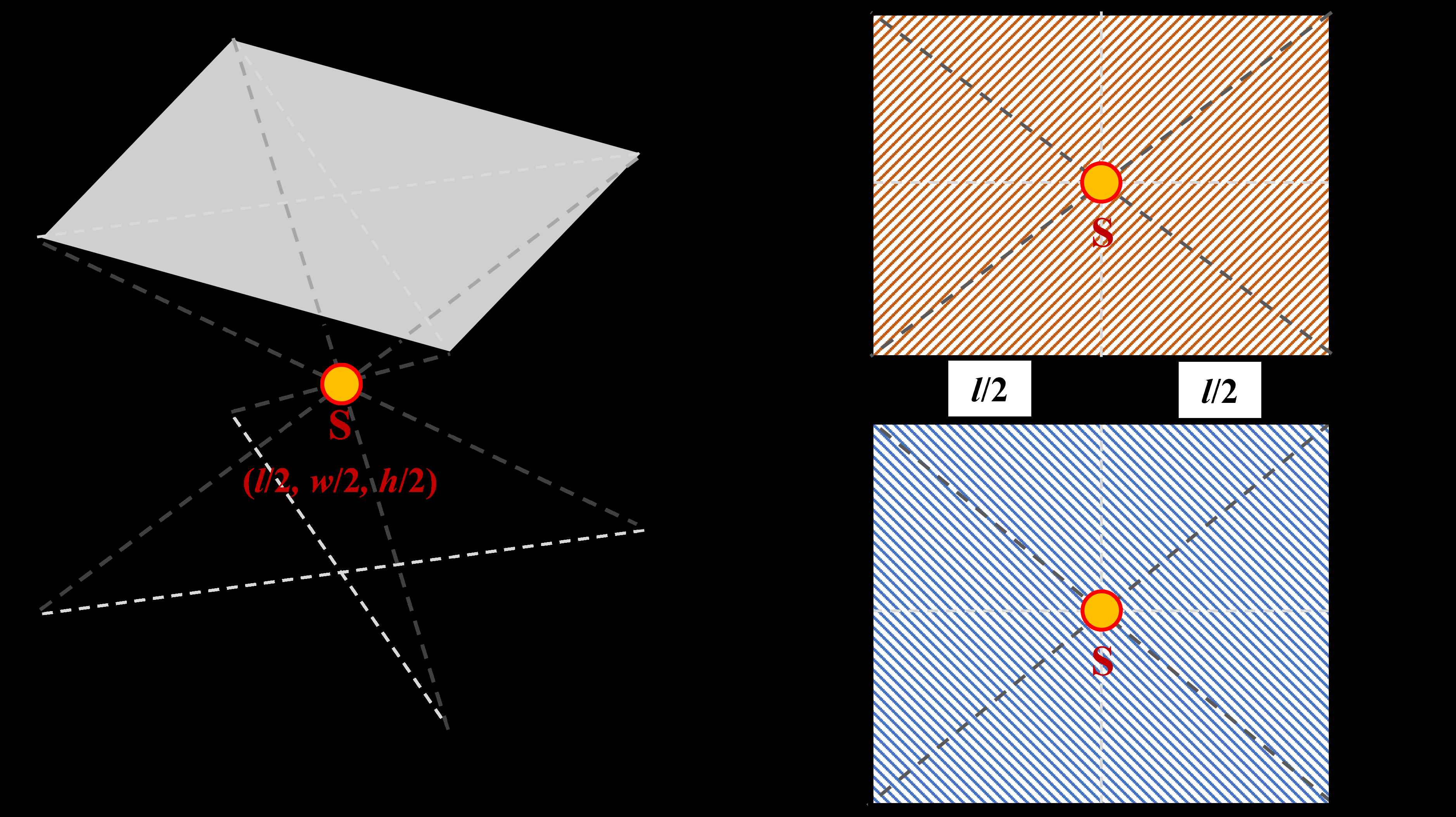
Fig. 2. Views of a room with a light source at coordinate (rand1∙l, rand2∙w, rand3∙h), without any interior objects.
By analogy, the solid angle subtended between S and the ceiling reads:
The solid angle subtended between S and the front wall reads:
The solid angle subtended between S and the rear wall reads:
The solid angle subtended between S and the left wall reads:
Finally, the solid angle subtended between S and the right wall reads:
It can also be shown that the sum of all solid angles within the room is always equal to 4π sr. In all scenarios, the relevant solid angle for each surface is then inserted into Equation (13) to obtain the necessary luminous intensity I to satisfy the MRSEspec.
The computation can also be extended to the case of room with objects. For simplicity, let us consider two objects, both come in a cuboid shape, as shown in Fig. 3.
Figure 3
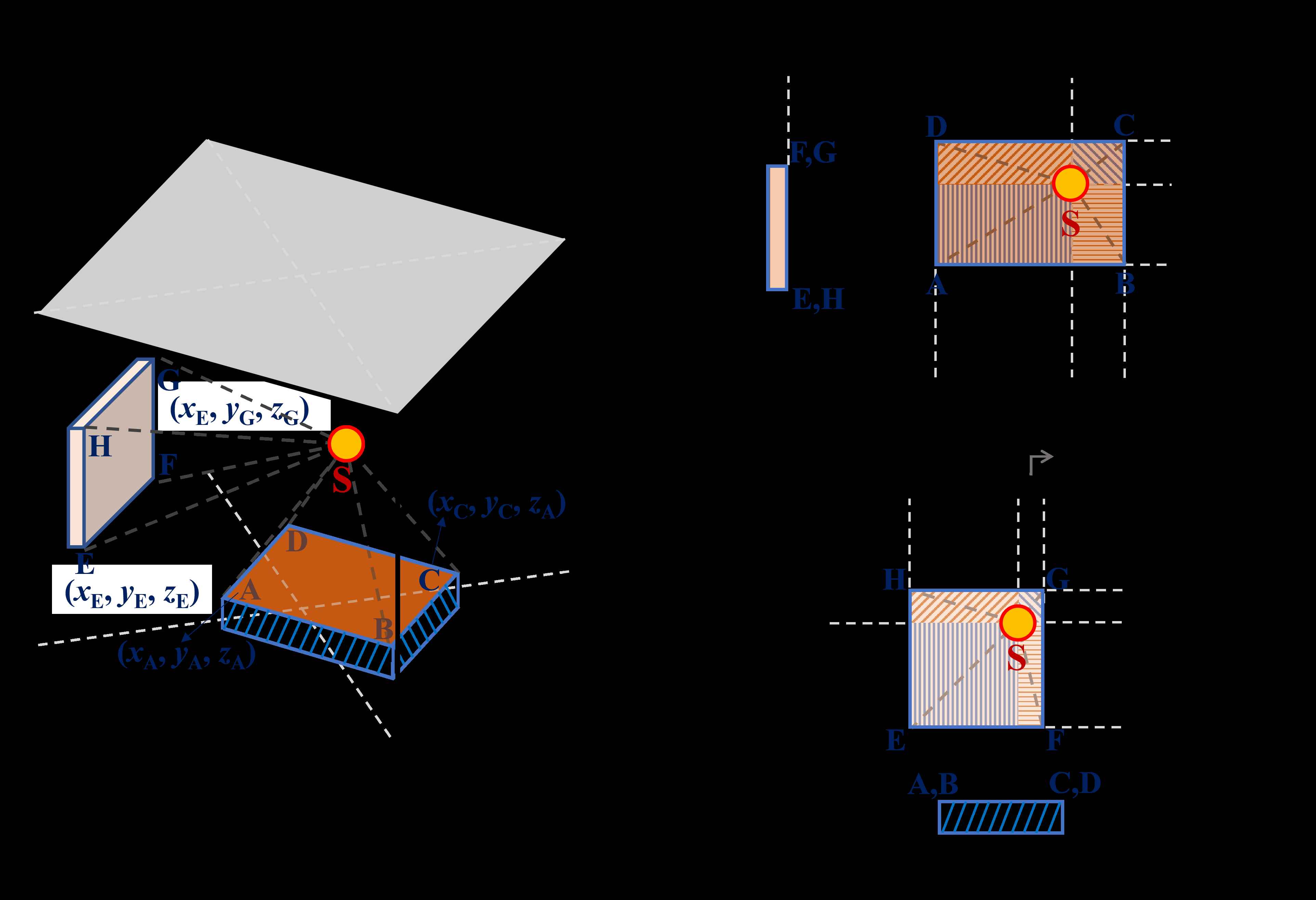
Fig. 3. Views of a room with a light source at coordinate (rand_1∙l, rand_2∙w, rand_3∙h), with two interior objects.
Object 1 lies horizontally on the floor and has a depth of zA, such that the vertices of its top surface are A, B, C, and D. Object 2 lies vertically on the left wall, such that the vertices of its outer surface are E, F, G, and H. It is assumed in Fig. 3 that xA < xS < xC, yA < yS < yC, yE < yS < yG, and zA < zS < zG; meaning that the projection of S falls within the plane of both objects.
The solid angle subtended between S and Object 1 (plane ABCD) reads:
The solid angle subtended between S and Object 2 (plane EFGH) reads:
The solid angle subtended between S and the floor now becomes the Ωf in Equation (18) subtracted by Ωo1, whereas the solid angle subtended between S and the left wall is now the ΩwL in Equation (22) subtracted by Ωo2.
2.4. LiDOs calculation table
Having known all the necessary information, one can now assemble the LiDOs calculation table, which should give a detailed description of the assigned parameters for each room surface and/or interior object. The calculation table is constructed based on ref. [1], with the additional columns of ρΩ, M, and MA, to suit the concept proposed in the earlier subsections. Table 1 displays the calculation table template for scenarios with interior objects.
Table 1
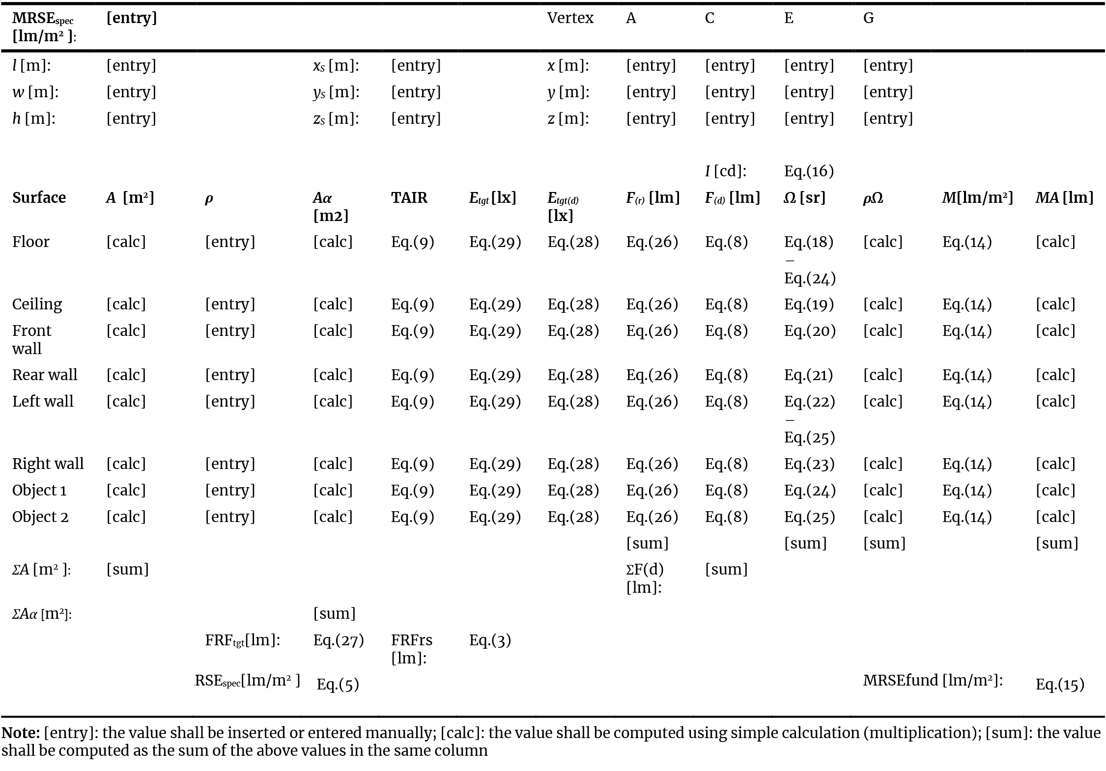
Table 1. Template of LiDOs calculation table for the scenario with interior objects.
The calculation steps are as follows:
- Define MRSEspec and insert/enter the value to the top cell of Table 1.
- Insert the room dimensions (l, w, h) and the isotropic light source’s position (xS, yS, zS).
- Insert the ρ of each room surface.
- Compute A and Aα (= A(1 – ρ)) of each surface, and their respective sum, i.e. ΣA and ΣAα.
- Compute the solid angle Ω subtended between the source and each surface, according to Equations (25) until (30). The sum of all solid angles should be equal to 4π (≈ 12.57) sr.
- Compute ρΩ for each surface and its sum (ΣρΩ) for all surfaces.
- Compute the necessary I of the source, using Equation (16).
- Compute F(d) at each surface, using Equation (8).
- Compute F(r), which is the first reflected flux of each surface, such that for the j-th surface, one reads:
- Compute FRFtgt, which is the sum of Fr,j:
In any case, FRFtgt = FRFrs. The latter shall be computed using Equation (3).
- Compute MRSEact using Equation (8). In any case, MRSEact = MRSEspec.
- Compute Etgt(d) at each surface, which is the ratio between Fd and of each surface:
- Compute Etgt at each surface, which is the sum of Etgt(d) and MRSEspec:
- Compute TAIR at each surface using Equation (9), or simply
- Compute M of each surface using Equation (14), followed with M∙A and its sum, i.e. ΣMA .
- Compute MRSEfund using Equation (15). Since MRSEspec is assumed constant, then MRSEfund = MRSEact= MRSEspec.
- Observe the TAIR at each surface and the total Fd. The ΣF(d) is always equal to 4πI. Modify those values whenever necessary by adjusting the source position (xS, yS, zS).
In scenarios with interior objects, one shall do additional calculations for Objects 1 and 2. Moreover, in the second step, it is also necessary to insert the coordinates of vertices A, C, E, G to represent the position of both objects. Note that the solid angles of the floor and the left wall are reduced by the solid angles of both objects respectively. The floor and left wall area is also reduced by the source-facing area of Objects 1 and 2 (i.e. planes ABCD and EFGH).
To accelerate the design process, the calculation tables have been provided as an MS Excel spreadsheet, which can be downloaded from the URL in the Appendix, under the tabs ‘Simple_w_obj’ (with objects). In using the spreadsheet, one only needs to insert the required values in the [entry] cells and then observe the TAIR at each surface and ΣF(d) as in Step 17 of the proposed algorithm.
where, in general, rand1 ≠ rand2 ≠ rand3. Similar assignments can be applied to the coordinates of planes ABCD and EFGH in the scenario with interior objects.
A modified version of the LiDOs calculation table has been provided in the attached spreadsheet, under the tabs ‘Optim_w_obj’ (with objects). One can insert the possible coordinates of the source and/or objects by modifying and copying the calculation row, each of which represents a different design combination, until a relatively large number (e.g. 1000) of random combinations has been created. Random search-based selection can be performed by sorting the relevant TAIR and/or ΣF(d) values, depending on the design objective. For example, if the primary design objective is to minimise the energy use, the combination that yields the smallest ΣF(d) shall then be selected. If the primary design objective is to maximise visual emphasis on a certain surface or object, the combination that yields the greatest TAIR at that surface shall then be selected.
3. Workflow examples
3.1. Verification
Prior to demonstrating the proposed concept in design practice, it is necessary to verify the equality of MRSEspec, MRSEact, and MRSEfund in any random scenarios. This is done by inserting random values of input variables on the LiDOs calculation table. Table 2 displays the arbitrarily chosen minimum and maximum values of MRSEspec, room dimensions and reflectances, and source and objects coordinates. The value of MRSE = 14 and 1800 lm/m2 respectively corresponds to ‘very dimly lit’ and ‘very brightly lit’ scale of spatial brightness (SB) levels [1,8-10].
Table 2
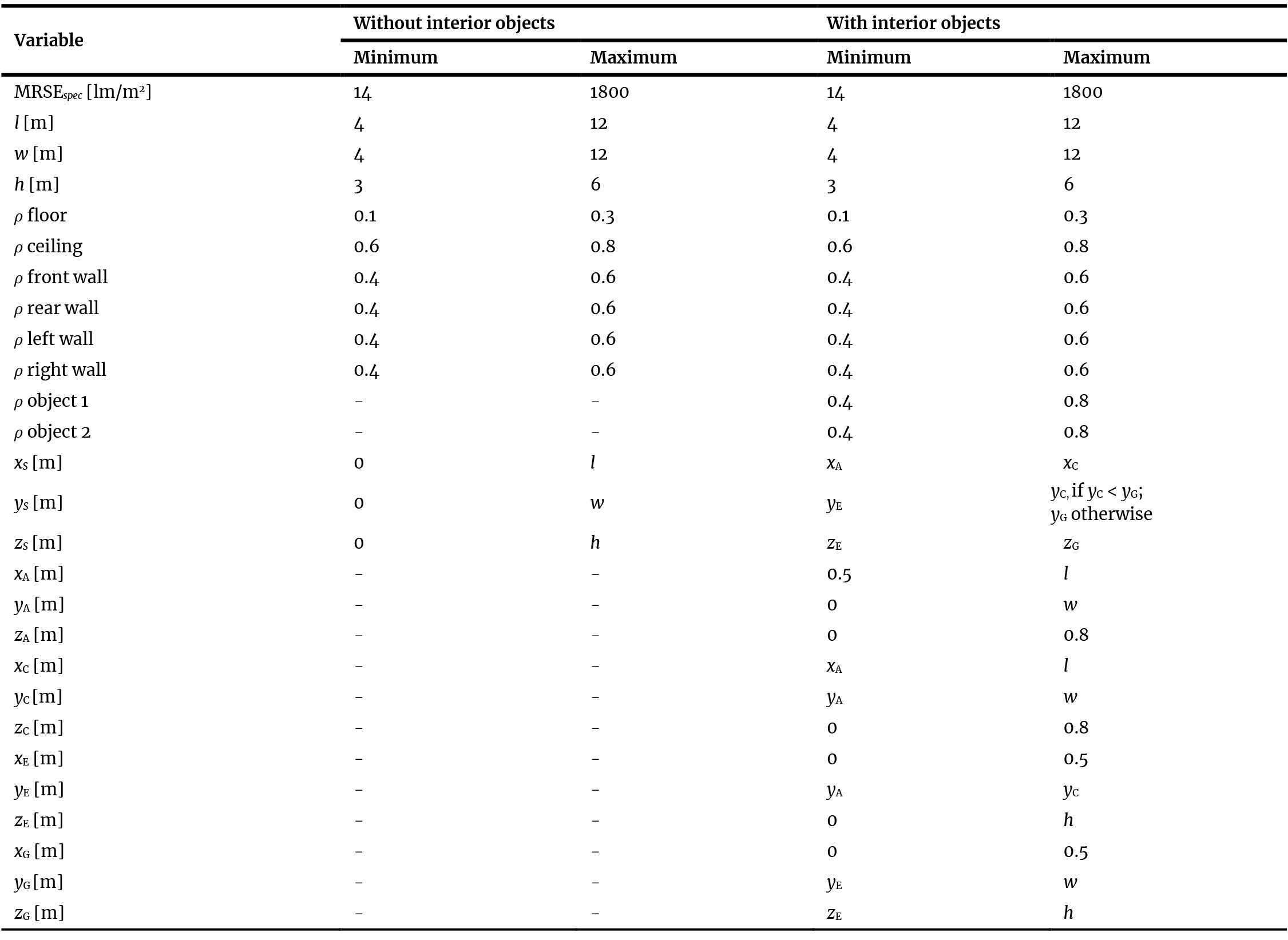
Table 2. Minimum and maximum values of input variables for testing the MRSE equality.
After creating 1000 random combinations of the input variables, the obtained MRSEspec, MRSEact, and MRSEfund can be compared to each other, whose results are shown in Fig. 4. In any random scenarios, the equality between MRSEspec, MRSEact, and MRSEfund is always achieved, verifying the mathematical proofs in Section 2.
Figure 4
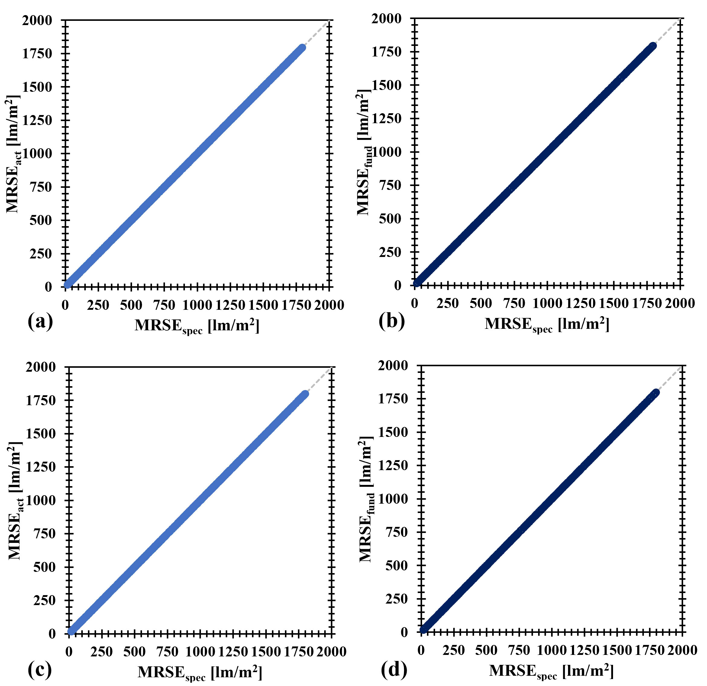
Fig. 4. Comparison between MRSEact and MRSEspec, and MRSEfund and MRSEspec in cases without interior objects (a), (b) and in cases with interior objects (c), (d).
To observe how the TAIR and luminous flux are distributed among the room surfaces, consider a room of 6 m 4 m 3 m, adopted from the typical reference office room [23]. The specified MRSE is fixed at 100 lm/m2, corresponding to the spatial brightness (SB) of ‘neither dimly lit nor brightly lit’, which is in the mid-range of SB-3.5~SB-4.5 [1,10]. The other input variables are arbitrarily chosen. By plugging the values into the provided LiDOs calculation table, one can immediately read the design output, as shown in Table 3.
Table 3
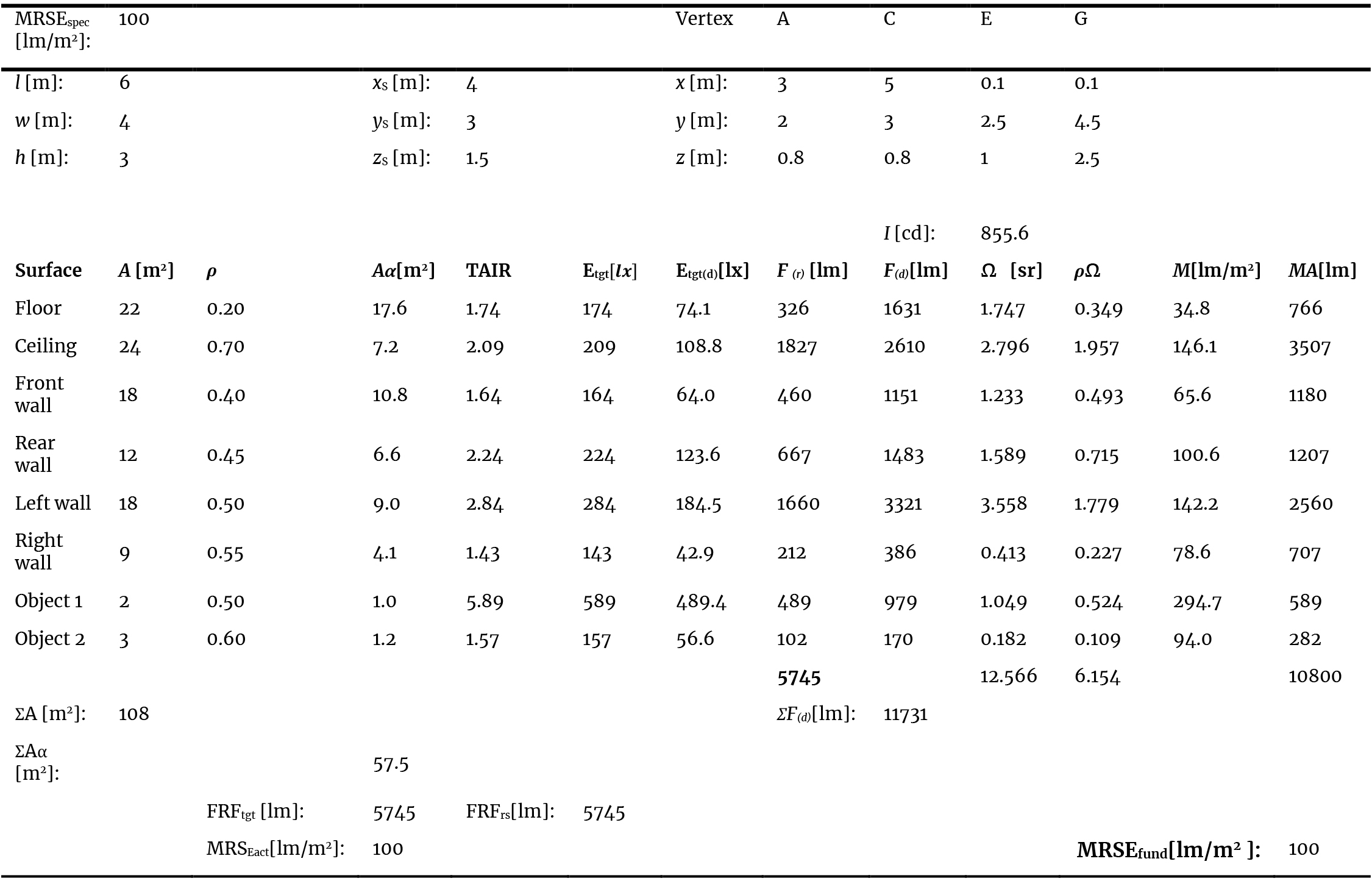
Table 3. Example of LiDOs calculation for the scenario with interior objects.
Since MRSE is basically the weighted average of M of all surfaces within the room, it is expected to have several surfaces with exitance greater than the MRSE, and several others with exitance smaller than the MRSE.
In general, the greatest exitance and thus also M/MRSE is expected at the ceiling, due to its surface reflectance [17]. However, in Table 3, the greatest exitance and M/MRSE is achieved at Object 1, due to its proximity to the light source.
The relation between M and TAIR is not necessarily proportional, particularly in rooms without interior objects. Thus, in some situations, a target surface may have high TAIR value (meaning that it receives large amount of total illuminance) but low exitance (meaning that it appears dim, instead of bright), which is likely to happen if the surface has relatively low reflectance. The TAIR at each surface is also different in number with M/MRSE.
Since
3.2. Random search-based selection
As a case study for the parametric exploration, consider the typical reference office room with interior objects as before, with fixed dimensions and reflectances. Plane ABCD has a fixed size of 2 m × 1 m at 0.8 m from the floor (e.g. representing a desk), while plane EFGH has a fixed size of 2 m × 1.5 m at 0.1 m from the left wall (e.g. representing a painting). By varying the remaining input variables in Table 4, a total of 1000 random combinations are generated.
Table 4
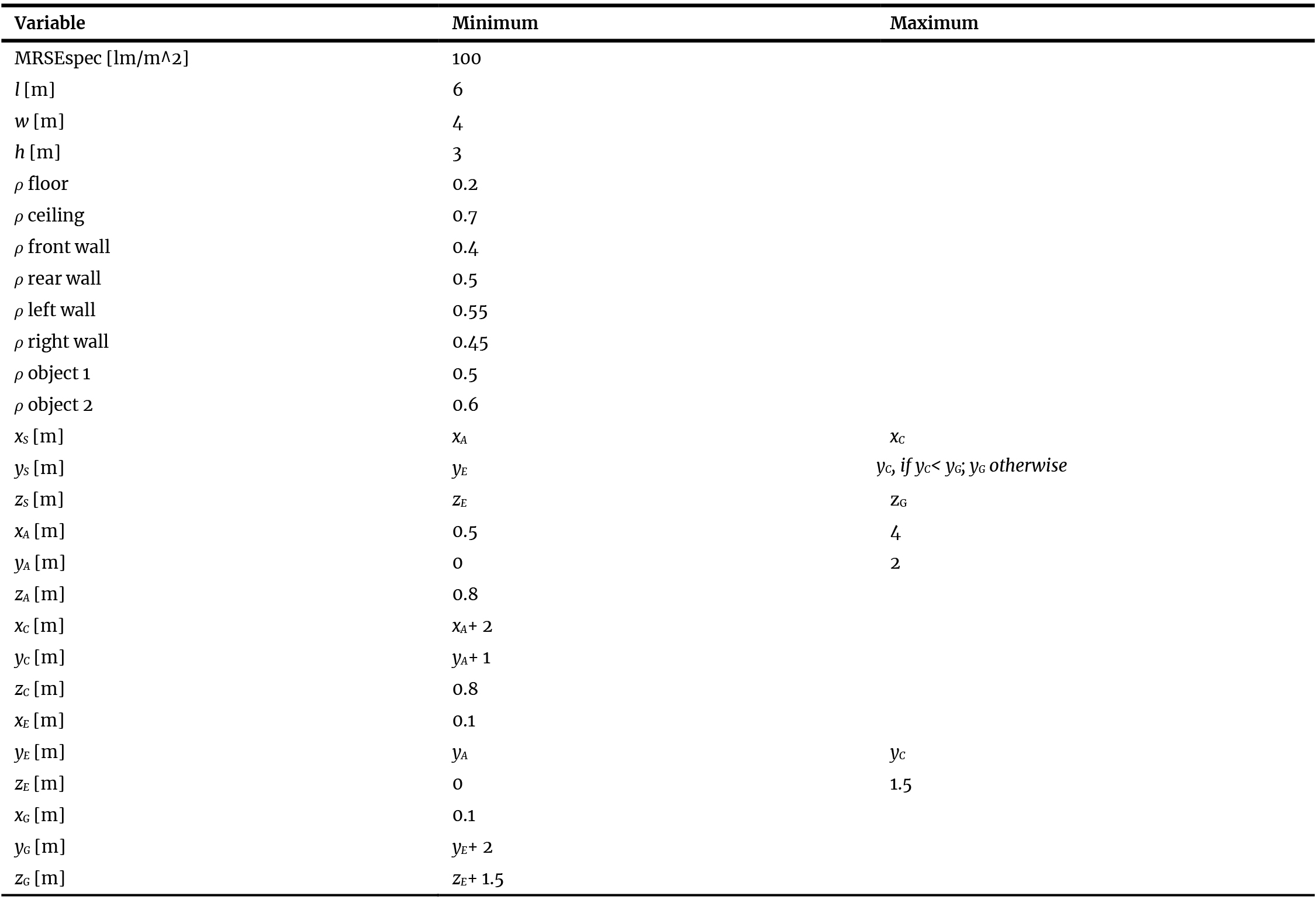
Table 4. Minimum and maximum values of input variables for random search-based selection.
Figure 5 displays the scatterplots showing the relation between TAIR and M/MRSE at the ceiling, floor, front wall, left wall, Object 1, Object 2 and the ΣFd. In each plot, the uppermost dot represents the design combination with the greatest TAIR and M/MRSE, thus indicating the highest visual emphasis. For the entire set of plots, the leftmost dot represents the design combination with the smallest ΣFd, thus indicating the minimum lighting energy.
Figure 5
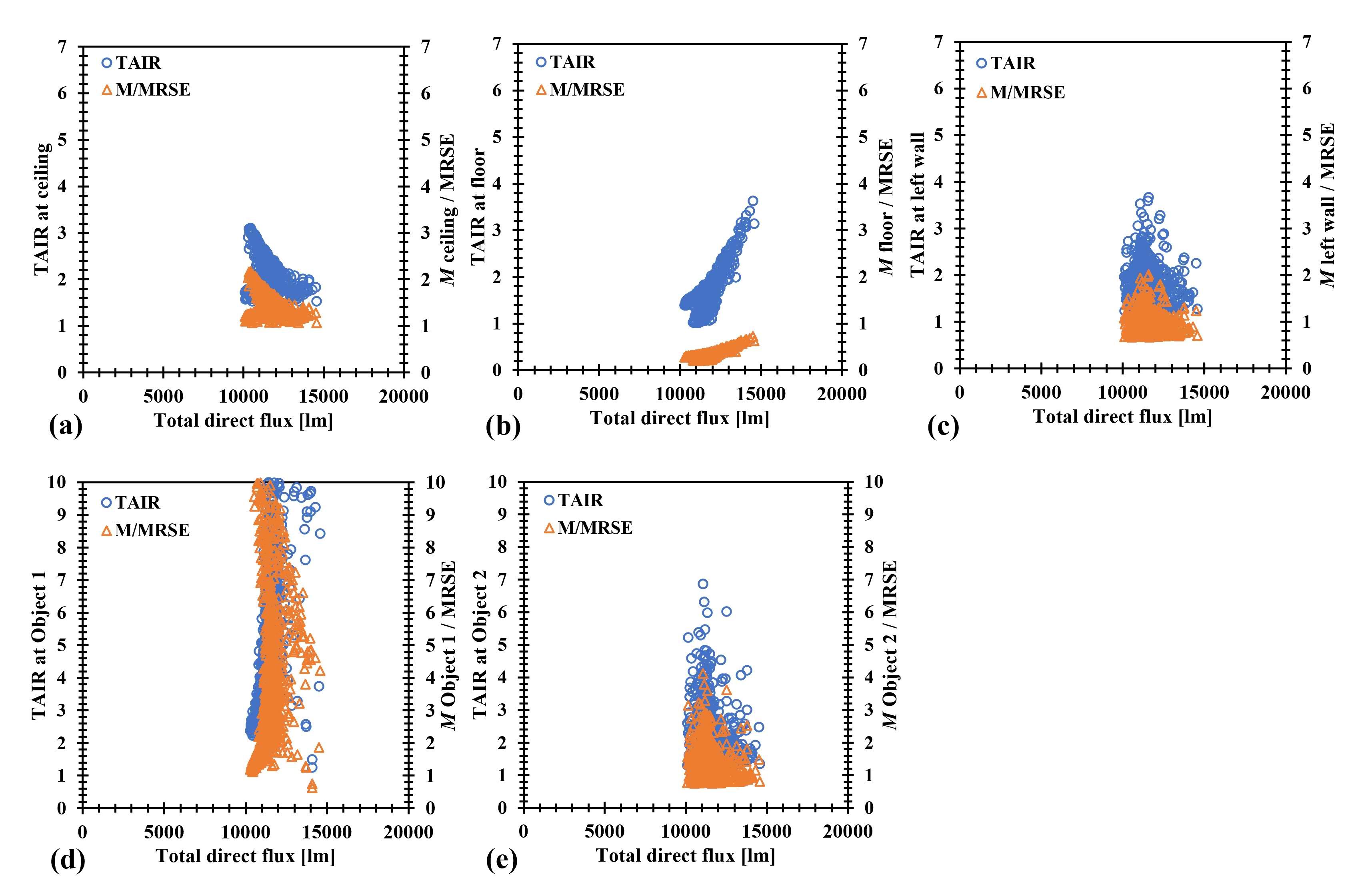
Fig. 5. Relation between TAIR and M/MRSE at (a) ceiling, (b) floor, (c) left wall, (d) Object 1, (e) Object 2, and the total direct flux in 1000 random design combinations with interior objects.
There is only one design combination giving the smallest lighting energy demand of all 1000 combinations.
However, the one that yields the greatest TAIR at one surface does not necessarily yield the greatest TAIR at the other surfaces. The decision shall then be made by the lighting designer as to which surface(s) are to be prioritised in terms of visual emphasis. For example, the designer may wish to maximise TAIR at the ceiling because it typically has the greatest reflectance, which is beneficial in increasing the ambient illuminance.
It is also possible to set a certain TAIR, not necessarily the maximum value, for a particular surface, and then select the design combination yielding that TAIR and the smallest ΣFd.
The large variabilities of TAIR values in Figs. 3d and 3e are mostly due to the relatively small area of the objects, compared to the room interior surfaces. In general, the smaller the size of the object, the greater choice of TAIR values that can be assigned to that object, since it has a larger ‘quota’ of ρj Aj(TAIRj – 1) as per Equation (7).
One can also parametrically explore the design by filtering the 1000 random combinations according to the acceptable TAIR ranges for several surfaces. For example, the designer may wish to have TAIR as follows: at the ceiling: 2~2.5, floor: 1~1.5, Object 1: 2~4, and Object 2: 3~5. The 1000 random combinations can then be sorted and any combinations that give TAIR outside those ranges can be eliminated. Among the remainder, the combination with the smallest ΣF(d) shall then be selected as optimum.
Table 5 displays the summary of the optimum design combinations based on various design objectives. Given the specified MRSE of 100 lm/m2, if the main objective is to minimise lighting energy, it is then recommended to install an isotropic light source with total luminous flux of 10285 lm at the suggested coordinate (first row of Table 5). If a more balanced setting of TAIR values is intended, it is then recommended to install an isotropic light source with total luminous flux of 11077 lm at the suggested coordinate (third row of Table 5), and so forth. Note that these are examples and not necessarily the only solutions, due to the random nature of Monte Carlo simulation. Despite the randomness, the presented results can provide general ideas on where the parametric exploration using random search-based selection process shall lead to.
Table 5
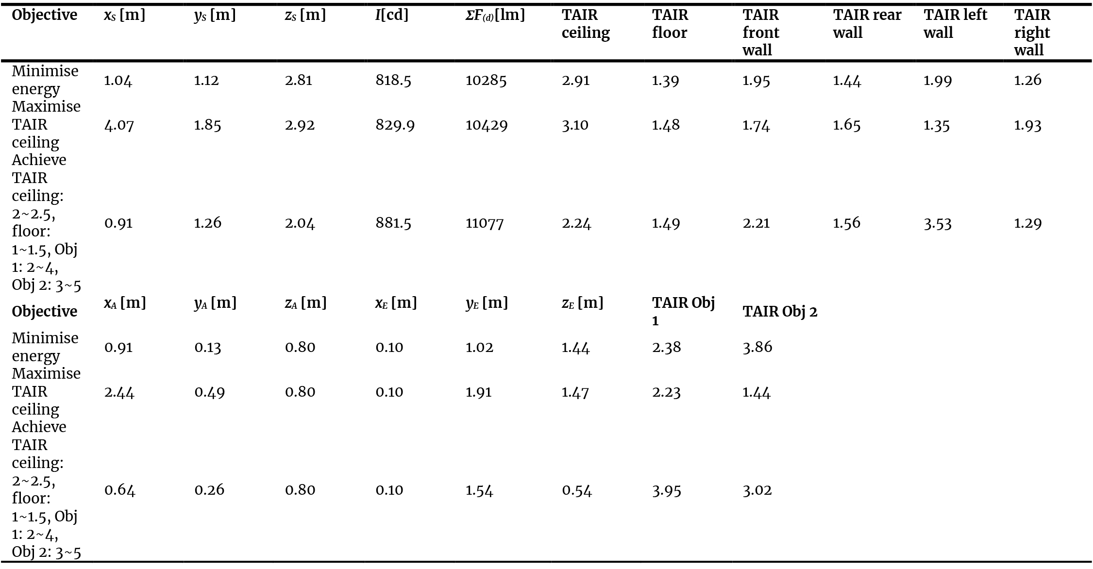
Table 5. Summary of the optimum design combinations based on various design objectives.
It should be noted that the use of Monte Carlo method in this case is mainly to introduce large variability of input variables, in order to verify the equality of MRSEspec, MRSEact, and MRSEfund in any random scenarios (Subsection 3.1) and to parametrically explore the design combinations (Subsection 3.2).
In Subsection 3.1, it has been shown analytically that MRSEspec = MRSEact = MRSEfund, so the number of random combinations does not really matter. In Subsection 3.2, however, changing the number of random combinations may result in different numerical outcomes.
Table 6 displays the optimum design variables (minimum ΣF(d) and maximum TAIR ceiling) based on various numbers of random combinations (m) and the corresponding ratio of the design variables at the given n to the previous n. It is observed that at m = 1000, the ratios are relatively stable at around 0.94 for the minimum ΣF(d) and at around 1.08 for the maximum TAIR ceiling. The choice of m = 1000 is thus deemed sufficient in this case.
Table 6
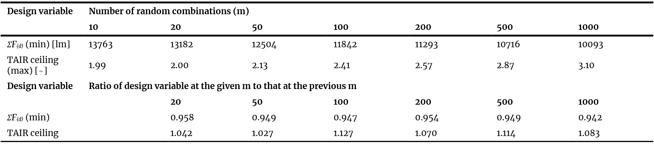
Table 6. Optimum design variables based on various number of random combinations and the corresponding ratios.
4. Discussion
4.1. Comparison with professional simulation tool
To compare the outcomes of the proposed approaches in this study with those of professional lighting simulation tools, three additional scenarios, namely A, B, and C, are introduced. In Scenario A, the source is placed in the centre of the room, which measures 4 m × 4 m × 4 m. In Scenario B, the source is placed in the room’s vertical axis but at 3 m from the floor, where the room also measures 4 m × 4 m × 4 m. In Scenario C, the source is placed at a random position in the room, which measures 8 m × 6 m × 4 m. All scenarios involve an isotropic point source of 1000 cd luminous intensity and different ρ values for each room surface. Details of the additional scenarios are listed in Table 7.
Table 7

Table 7. Three additional scenarios in the comparison with professional lighting simulation tool.
The three additional scenarios are modelled in the simulation tool DIALux evo [24], which is largely popular for lighting design in practice. It has been shown elsewhere that DIALux evo was validated against the test cases of CIE 171:2006 [25,26] with high accuracy, particularly for electric lighting scenes. In the simulation, the maintenance factor is set to 1, meaning that no light loss factors whatsoever exist. The light source is modelled by introducing the relevant IES file.
There are two ways to compute MRSE in DIALux evo. Both approaches are based on the surface luminous exitance, i.e. according to Equation (1). The first approach is by simulating the average of total (direct + indirect) illuminance received on each surface (Etot,j) and multiplying it with ρj to yield the luminous exitance (Mj). The second approach is by simulating the average surface luminance of each surface (Lj). Assuming all surfaces are Lambertian, Mj can thus be estimated as πLj. MRSE from the former is denoted MRSEevo(E), whereas that from the latter is denoted MRSEevo(L). Table 8 lists the comparison results between MRSE obtained from DIALux evo simulation and the MRSEspec as approximated by inversing Equation (12) of this study.
Table 8

Table 8. Comparison results between MRSE obtained from DIALux evo simulation (MRSEevo(E) and MRSEevo(L)) and MRSEspec approximated using Equation (12); all units in lm/m2.
It is observed that MRSEevo(E) and MRSEevo(L) are very close to each other and thus can be considered equal, which means that DIALux evo also assumes that all surfaces are Lambertian, unless modified otherwise. The approximated MRSEspec is also relatively close to the MRSEevo, with the greatest difference being 5 lm/m2 in Scenario C. Therefore, it has been proven that the approximation of MRSEspec using the solid angle method in this study is consistent not only in theoretical calculation, but also in comparison with professional simulation tools. In general, the results also show consistency or agreement with simulation results. However, further studies are still required in the future to prove the validity of the model against real-world lighting scenarios. This is because the actual luminous intensity of an approximately isotropic light source may not be exactly uniform in all directions, the interior surfaces may not be perfectly Lambertian and have homogenous reflectance, and the inter-reflected illuminance component is most likely not constant throughout the space. Nevertheless, the use of lighting simulation tool in the design process can thus be extended to evaluate not only the task illuminance-based metrics [27], but also the luminance- or exitance-based metrics such as MRSE.
For informative purposes, Fig. 6 displays the rendered images and false colour maps of the total illuminance (Etot) and surface luminance of the room surfaces, as seen from the front wall facing to the rear wall, in Scenarios A, B, and C, using DIALux evo. Due to the given elevation of the source, the ceiling receives the greatest Etot and appears the brightest in Scenarios B and C. It is also observed that while the left and right walls receive equal amounts of Etot due to symmetry (cf. Figs. 6(d), 6(e), 6(f)), the surface luminance of both surfaces are not equal (cf. 6(g), 6(h), 6(i)). This is because the left wall has ρ = 0.6, whereas the right wall has ρ = 0.4 (cf. Table 6), such that the former has a greater surface luminance, as well as luminous exitance, compared to the latter. Consequently, the left wall shall appear brighter than the right wall. This shows the importance of properly designing the surface luminances, rather than merely the total illuminances, in determining the MRSE within the room.
Figure 6
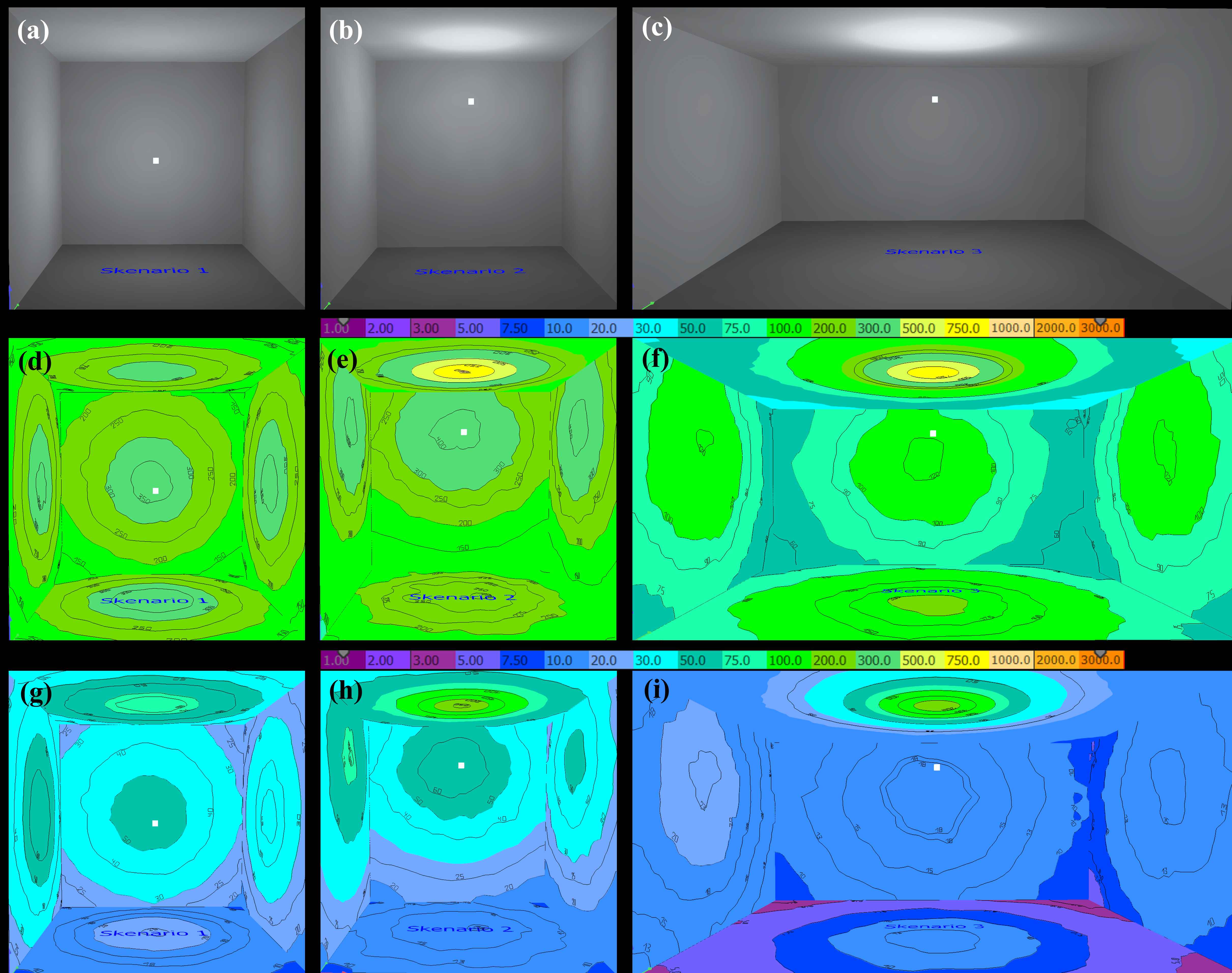
Fig. 6. Rendered images (a, b, c) and false colour maps of the total illuminance (d, e, f) and surface luminance (g, h, i) of the room surfaces in Scenarios A, B, and C.
4.2. General discussion
From the technical perspective, it had been understood [14,15] that the original MRSE expression in [12] is an approximation, although the errors would be acceptable for general lighting practice [28], and that the MRSE in general should be expressed as in Equation (1). However, in Equation (1), the luminous exitance for each surface is not described as a function of the light source characteristics. This study thus bridges the gap by providing an algorithm to systematically derive the MRSE, which is possible for isotropic sources due to the constant IΩ.
Several simplified assumptions in the proposed closed-form analytical formulation. For instance, objects are positioned such that the source projection lies within their planes. If this is not the case, the solid angle can be computed by geometrical subtraction. The effect of occlusion or shadow from three-dimensional objects is also ignored. Nevertheless, these simplifications are considered necessary so that the algorithm in LiDOs procedure, which is meant to be a simple design tool, can still be in use.
For high accuracy calculation, numerical approaches using the view factor method are recommended; however, the use of simple spreadsheet might not be sufficient for applying such approach
While the case study here is meant to be hypothetical, applying a single source is relatively common in small indoor spaces, such as home office rooms [29,30].
Although most of them use a ceiling lamp, leaving practically little amount of direct upward flux distribution, more flexible options are now available using free-standing luminaires as illustrated in Fig. 1. Other than that, it is also possible to find pendant luminaires with translucent shade [27] in real-world scenarios, which roughly gives a uniform LID.
As mentioned in Section 1, the general idea of the LiDOs procedure is applying ‘reverse’ lighting design process, where the lighting designer first envisions the design concept based on the relevant objectives, followed with devising appropriate direct flux distribution that can be attributed to the necessary light sources and their characteristics. However, in a real design practice, the building or project owners, particularly in residential settings, often state beforehand their preference towards a certain type of light sources or luminaires. In that situation, the lighting designer often needs to adjust and adapt his/her design idea based on such constraint. In our opinion, this is one of the actual challenges along this topic, that is, how to apply LiDOs procedure under pre-defined constraints, while still achieving the design objectives.
While this study focuses on a single isotropic source, it shall also be possible to extend the concept to multiple isotropic sources. When there are multiple sources, it is possible to estimate the MRSE by applying superposition of the F(d) contributed from each source. This would be beneficial in cases where there are several objects that need to be emphasised, which are, for instance, placed on opposing walls or corners within the room, in such a way that a single light source would be insufficient to cover all of them.
When the source is not isotropic, the luminous intensity is not constant. However, if the intensity distribution can be expressed as a simple and continuous function, such as in the British Zonal (BZ) distribution types [32,33], the exact F(d) can be analytically obtained from solving the integral in that equation. In that case, the solid angle shall be converted to plane angle, and the integration boundaries shall be defined according to the subtended plane (instead of solid) angle. For the case of isotropic sources with obstructed base such as in Fig. 1, the luminous intensity can be estimated by dividing the total luminous flux with the unobstructed solid angle, which is 4π – 2π(1 – cos γ) = 2π(1 + cos γ) (in steradians), where γ is half of the plane angle of the obstruction.
As a side note, while the direct flux component in this case can be determined accurately, the indirect flux component in any case is still an approximation due to the assumption that MRSE is a single representation of the indirect illuminance and is constant all over the room surfaces. Therefore, the predicted MRSE may not exactly equal to the real ‘true’ MRSE obtained from the original MRSE equation [28], even though the errors are deemed reasonable acceptable, including for teaching and design practice, as long as the limitations are acknowledged [15].
Follow-up of this study can be directed towards observing more complex and realistic room lighting scenarios, for instance, the presence of light sources with actual intensity distribution, multiple light sources, and integration with daylight. Furthermore, in terms of the non-visual effect, it is known that increasing surface reflectance can increase the effectiveness of circadian stimulus by up to 3.6 times more than intensifying the source luminous flux [34], meaning that the design focus should be directed towards not only the light sources, but also the room surfaces. Other operational issues related with the energy demand, such as the use of occupancy sensors in such rooms [35-37], can also be suggested for future studies.
5. Conclusion
This study has provided closed-form analytical solution for MRSE in scenarios with isotropic light source for applying LiDOs procedure in a room in such cases, using solid angles subtended between the isotropic light source and the room surfaces. It has been shown that in the case of an isotropic source, the intended ambient illumination can always be achieved, indicated by the equality between the specified and actual MRSE. This is possible due to the exact computation of the direct flux received by each surface within the room, due to the constant luminous intensity of the source.
The LiDOs calculation tables for scenarios of rooms with interior objects have been developed and tested with worked examples of a simple room with various surface reflectances, under the constraint of having an isotropic light source in the room. Random search-based selection method using Monte Carlo simulation with 1000 combinations has been provided, also with worked examples, to parametrically explore the outcomes based on the design objectives such as minimising lighting energy, maximising visual emphasis in terms of TAIR and/or M/MRSE, or achieving a specific target of visual emphasis while minimising energy.
In general, this study has proposed a new insight on the LiDOs application under the design constraint of room with isotropic light source, and how the MRSE can be related with the relevant design input variables, which may help lighting practitioners in coming up with design solutions under constraint, in achieving the intended room ambient illumination and spatial brightness, while still saving electric lighting energy.
Funding
This research received no external funding.
Author Contributions
Conceptualization, R.A.M.; Writing—Original Draft, R.A.M, T.N.; Methodology, R.A.M., I.M.H.; Writing—review and editing, R.A.M., I.M.H., T.N.; Visualization, Validation, Data curation, and Resources, R.A.M., I.M.H.; Supervision, Funding acquisition, Project Administration, R.A.M. All authors have read and agreed to the published version of the manuscript.
Declaration of competing interest
The authors declare no conflicts of interest.
Supplementary information
The LiDOs calculation spreadsheet in this study can be downloaded at: https://bit.ly/LiDOs_omega.
References
- C. Cuttle, Extending the lighting design objectives procedure for holistic lighting solutions, Lighting Research and Technology, 54:7 (2022) 631-656. https://doi.org/10.1177/14771535211061044
- C. Cuttle, An introduction to LiDOs, Lighting Research and Technology, 54:8 (2022) 628-629. https://doi.org/10.1177/14771535221132885
- P.R. Boyce, H.M. Brandston, C. Cuttle, Indoor lighting standards and their role in lighting practice, Lighting Research and Technology, 54:7 (2022) 730-744. https://doi.org/10.1177/14771535221126413
- P. Chen, L., Wang, A. Wang, J. Yu, G. Kong, Y. Wu, Suitability comparison of heuristic algorithms for the execution of lighting design objectives (LiDOs) procedure, Building and Environment, 242 (2023) 110539. https://doi.org/10.1016/j.buildenv.2023.110539
- S. Fotios, T. Goodman, Editorial: Research on lighting design, Lighting Research and Technology, 54:7 (2022) 627. https://doi.org/10.1177/14771535221134859
- S. Roy, S. Majumder, S. Bhattacharya, I.H. Sardar, (2021), Simulation and analysis of the effects of room surface reflectance combinations on a proposed retrofit illumination system of an office, Journal of Engineering, Design and Technology, 19:6 (2021) 1620-1647. https://doi.org/10.1108/JEDT-10-2020-0400
- S. Roy, P. Satvaya, The effects of lamp types and surface reflectance combinations on the subjective perception of a simulated lit hospital ward environment, Facilities, 40:3 (2022) 697-718. https://doi.org/10.1108/F-01-2022-0013
- J. Duff, K. Kelly, C. Cuttle, Spatial brightness, horizontal illuminance and mean room surface exitance in a lighting booth, Lighting Research and Technology, 49:1 (2017) 5-15. https://doi.org/10.1177/1477153515597733
- J. Duff, K. Kelly, C. Cuttle, Perceived adequacy of illumination, spatial brightness, horizontal illuminance and mean room surface exitance in a small office. Lighting Research and Technology, 49:2 (2017) 133-146. https://doi.org/10.1177/1477153515599189
- A. Durante, K. Kelly, Investigating mean room surface exitance values for office lighting. Lighting Research and Technology, 54:7 (2022) 657-673. https://doi.org/10.1177/14771535211044665
- C. Cuttle, Towards the third stage of the lighting profession, Lighting Research and Technology, 42:1 (2010) 73-93. https://doi.org/10.1177/1477153509104013
- C. Cuttle, A new direction for general lighting practice, Lighting Research and Technology, 45:1 (2013) 22-39. https://doi.org/10.1177/1477153512469201
- C. Cuttle, A fresh approach to interior lighting design: the design objective - direct flux procedure, Lighting Research and Technology, 50:8 (2018) 1142-1163. https://doi.org/10.1177/1477153517734401
- J. Duff, G. Antonutto, S. Torres, On the calculation and measurement of mean room surface exitance. Lighting Research and Technology, 48:3 (2016) 384-388. https://doi.org/10.1177/1477153515593579
- J.T. Duff, Research Note: On the magnitude of error in the calculation of mean room surface exitance. Lighting Research and Technology, 48:6 (2016) 780-782. https://doi.org/10.1177/1477153516659519
- R.A. Mangkuto, On the assignment of target/ambient illuminance ratio in designing mean room surface exitance. LEUKOS, 21:1 (2025) 19-33. https://doi.org/10.1080/15502724.2023.2297961
- R.A. Mangkuto, Notes on the assignment of target/ambient illuminance ratio on the last surface in lighting design objectives procedure. LEUKOS, in press (2026). https://doi.org/10.1080/15502724.2026.2613410
- Cahaya Mas Lights, Lampu Hias Gantung Cafe / Dapur / Ruang Makan / Kamar / Dll | Minimalist Modern Nordic Bulat/Bola Kaca Gold FULLSET (CahayaMasLights), Available at https://www.tokopedia.com/cahayamaslights/lampu-hias-gantung-cafe-minimalist-modern-bulat-bola-kaca-gold-fullset, Accessed on 13 April 2026.
- W.E. Sumpner, The diffusion of light, Proceedings of the Physical Society of London, 12 (1892) 10-29. https://doi.org/10.1088/1478-7814/12/1/304
- R.H. Simons, A.R. Bean, Lighting Engineering: Applied Calculations, Architectural Press: Oxford, UK, 2001. https://doi.org/10.1016/B978-075065051-9/50014-3
- International Organization for Standardization (ISO), ISO/IEC Guide 98-3:2008. Uncertainty of measurement - Part 3: guide to the expression of uncertainty, ISO: Geneva, Switzerland, 2008.
- R.A. Mangkuto, B. Paramita, Design optimisation of mean room surface exitance and total corneal illuminance using Monte Carlo simulation, Building Simulation, 15:11 (2022) 1869-1882. https://doi.org/10.1007/s12273-022-0899-7
- D. van Dijk, W.J. Platzer, W.J. Reference office for thermal, solar and lighting calculations, International Energy Agency (IEA) Task 27, Report no. swift-wp3-tno-dvd-030416, 2003.
- DIAL GmBH, DIALux, 2026. Available online at: https://www.dialux.com/en-GB/, Accessed on 13 April 2026.
- Commission Internationale de l'Éclairage (CIE), CIE 171:2006 - Test cases to assess the accuracy of lighting computer programs, CIE: Vienna, Austria, 2006.
- R.A. Mangkuto. Validation of DIALux 4.12 and DIALux evo 4.1 against the Analytical Test Cases of CIE 171:2006. LEUKOS, 12:3 (2016) 139-150. https://doi.org/10.1080/15502724.2015.1061438
- A. Davoodi, P. Johansson, M. Aries, The use of lighting simulation in the evidence-based design process: A case study approach using visual comfort analysis in offices, Building Simulation, 13:1 (2020) 141-153. https://doi.org/10.1007/s12273-019-0578-5
- P. Raynham, J. Unwin, L. Guan, A new metric to predict perceived adequacy of illumination, Lighting Research and Technology, 51:4 (2019) 642-648. https://doi.org/10.1177/1477153519828416
- C.N.D. Amorim, N.G. Vasquez, B. Matusiak, J. Kanno, N. Sokol, J. Martyniuk-Peczek, S. Sibilio, Y. Koga, G. Ciampi, M. Waczynska, Lighting conditions in home office and occupant's perception: An international study, Energy and Buildings, 261 (2022) 111957. https://doi.org/10.1016/j.enbuild.2022.111957
- N.G. Vasquez, C.N.D. Amorim, B. Matusiak, J. Kanno, N. Sokol, J. Martyniuk-Peczek, S. Sibilio, M. Scorpio, Y. Koga, Lighting conditions in home office and occupant's perception: Exploring drivers of satisfaction, Energy and Buildings, 261 (2022) 111977. https://doi.org/10.1016/j.enbuild.2022.111977
- N. Sokol, J. Martyniuk-Peczek, B. Matusiak, C.N.D. Amorim, M. Waczynska, J. Kurek, N.G. Vasquez, S. Sibilio, J.R. Kanno, M. Scorpio, M. Nazari, Y. Koga, 'Personas for lighting'. Three methods to develop personas for the indoor lighting environment, Energy and Buildings, 278 (2023): 112580. https://doi.org/10.1016/j.enbuild.2022.112580
- J.A. Lynes, Does the British Zonal System have a future?, Lighting Research and Technology, 11:3 (1979) 150-153. https://doi.org/10.1177/14771535790110030201
- W.R. Stevens, Building Physics: Lighting. - Seeing in the Artificial Environment, Pergamon: Oxford, UK, 1969.
- Q. Dai, Y. Huang, L. Hao, Y. Lin, K. Chen, Spatial and spectral illumination design for energy-efficient circadian lighting, Building and Environment, 146 (2018) 216-225. https://doi.org/10.1016/j.buildenv.2018.10.004
- S. Chitnis, N. Somu, A.M. Kowli, Occupancy estimation with environmental sensors: The possibilities and limitations, Energy and Built Environment, 6:1 (2025) 96-108. https://doi.org/10.1016/j.enbenv.2023.09.003
- W. Loengbudnark, K. Khalilpour, G. Bharathy, A. Voinov, L. Thomas, Impact of occupant autonomy on satisfaction and building energy efficiency, Energy and Built Environment, 4:4 (2023) 377-385. https://doi.org/10.1016/j.enbenv.2022.02.007
- S. Zhan, A. Chong, Building occupancy and energy consumption: Case studies across building types, Energy and Built Environment, 2:2 (2021) 167-174. https://doi.org/10.1016/j.enbenv.2020.08.001
2383-8701/© 2026 The Author(s). Published by solarlits.com. This is an open access article distributed under the terms and conditions of the Creative Commons Attribution 4.0 License.